Chapter 16

Grading

Beyond creating streets and sewers, cul-de-sacs, and inlets, much of what happens to the ground as a site is being designed must still be determined. Describing the final plan for the earthwork of a site is a crucial part of bringing the project together. This chapter examines feature lines and grading groups, which are the two primary tools of site design. These two functions work in tandem to provide the site designer with tools for completely modeling the land.

In this chapter, you will learn to:

  • Convert existing linework into feature lines
  • Model a simple linear grading with a feature line
  • Model planar site features with grading groups

Working with Grading Feature Lines

There are two types of feature lines: corridor feature lines and grading feature lines. Corridor feature lines are discussed in Chapter 10, “Basic Corridors,” and grading feature lines are the focus of this chapter. It's important to note that grading feature lines can be extracted from corridor feature lines, and you can choose whether or not to dynamically link them to the host object.

As discussed in Chapter 4, “Surfaces,” terrain modeling can be defined as the manipulation of triangles created by connecting points and vertices to achieve Delaunay triangulation. In the AutoCAD® Civil 3D® software, the creation of the feature line object adds a level of control and complexity not available to 3D polylines. In this section, you look at the feature line, various methods of creating feature lines, some simple elevation edits, planar editing functionality, and labeling of the newly created feature lines.

Accessing Grading Feature Line Tools

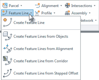
The Feature Line creation tools can be accessed from the Home tab's Create Design panel, as shown in Figure 16.1.

Figure 16.1 The Feature Line drop-down menu on the Create Design panel

16.1

The Feature Line editing tools can be accessed via the Feature Line contextual tab (see Figure 16.2). To access the Feature Line contextual tab you can select a feature line and the Feature Line contextual tab is activated, or from the Modify tab ⇒ Design panel choose Feature Line.

Figure 16.2 The Feature Line contextual tab accessed by selecting an existing feature line.

16.2

One thing to remember when working with feature lines is that they do belong in a site, as shown in Figure 16.3. Feature lines within the same site snap to each other in the vertical direction and can cause some confusion when you're trying to build surfaces.


Understanding Parent Sites
If you're experiencing some weird elevation data along your feature line, be sure to check out the parent site. If the concept of a parent site or sites in general doesn't make much sense to you, be sure and look at Chapter 5, “Parcels,” before going too much further. Sites are a major part of the way feature lines interact with each other, and many users who have problems with grading are the same users who are ignoring sites.

Figure 16.3 Feature lines are located in the Sites branch in Prospector.

16.3

The next few sections break down the various tools in detail. You'll use almost all of them in this chapter, so in each section you'll spend some time getting familiar with the available tools and the basic concepts behind them.

Creating Grading Feature Lines

certobjective

There are five primary methods for creating feature lines, as shown previously in Figure 16.1. They generate similar results but have some key differences:

Create Feature Line

The Create Feature Line tool allows you to create a feature line from scratch, assigning elevations as you go. These elevations can be based on direct data input at the command line, slope information, or surface elevations.

Create Feature Lines From Objects

The Create Feature Lines From Objects tool converts lines, arcs, polylines, and 3D polylines into feature lines. This process also allows elevations to be a constant elevation, assigned from a grading group, or assigned from a surface. You are given the option as to whether you want the original objects to be deleted or whether to weed points.

Create Feature Lines From Alignment

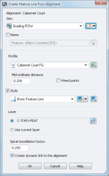
The Create Feature Lines From Alignment tool allows you to build a new feature line from an alignment, using a profile to assign elevations. This feature line can be dynamically tied to the alignment and the profile, which limits your ability to edit it directly, but makes it easy to generate 3D design features based on horizontal and vertical controls of other objects. If the feature line created from an alignment is not dynamically linked, then any of the feature line editing commands can be used.

Create Feature Line From Corridor

The Create Feature Line From Corridor tool is used to export a grading feature line from a corridor feature line. The feature line created from a corridor feature line keeps a dynamic link to the corridor.

Create Feature Line From Stepped Offset

The Create Feature Line From Stepped Offset tool is used to create a feature line from an offset and the difference in elevation from a feature line, survey figure, polyline, or 3D polyline. The feature line created from a stepped offset does not keep a dynamic link to the original feature line.

You explore each of these methods in the next few exercises. In this exercise, you will be creating a swale from feature lines.

1. Open the CreatingFeatureLines.dwg or CreatingFeatureLines_METRIC.dwg file. (Remember, all data can be downloaded from www.sybex.com/go/masteringcivil3d2013.)
This drawing has a polyline inset from the outer perimeter of the subdivision, and a polyline at the proposed centerline of an overland swale.

UnFigure

2. From the Home ⇒ Create Design panel, choose Feature Line ⇒ Create Feature Line to display the Create Feature Lines dialog.
You need to create a new site in which to put the swale. Just like parcels, grading objects will react with like objects in a site. So by isolating this swale, you can ensure that everything will be drawn properly before committing it to a site.

UnFigure

3. Click the Create New button to the right of the site name. The Site Properties dialog appears.
4. Enter Swale for the name of this site, and click OK to dismiss the Site Properties dialog.
The Create Feature Lines dialog should now look like Figure 16.4.

Figure 16.4 The Create Feature Lines dialog

16.4
5. Click OK to accept the Create Feature Lines dialog.
6. At the Specify start point: prompt, use an Endpoint Osnap to pick the right end of the line (closest to the red line).
7. At the Specify elevation or [Surface]: prompt, enter S SoftEnter to use a surface to set elevation information.
If there were multiple surfaces in the drawing, then the Select Surface dialog would appear and you would use the drop-down to choose EG, and click OK. However, since you only have one surface in this drawing currently, there is no need to state what surface to use.
8. At the Surface elevation: prompt, press SoftEnter to accept the default surface elevation offered on the command line.
9. At the Specify the next point or [Arc]: prompt, use an Endpoint Osnap to pick the left end of the line.
10. At the Specify grade or [SLope Elevation Difference SUrface Transition]: prompt, enter -5.2 SoftEnter to set the grade between points.
11. Press SoftEnter to end the command.
Your screen should look like Figure 16.5.

Figure 16.5 Setting the grade between points

16.5

Assigning Names
Looking back at Figure 16.4, note that there is an unused option for assigning a Name value to each feature line. Using names does make it easier to pick feature line objects if you decide to use them for building a corridor object. The Name option is available for each method of creating feature line objects, but will generally be ignored for this chapter, except for one exercise covering the renaming tools available.
This method of creating a feature line connecting a few points seems pretty tedious to most users. In the next portion of the exercise, you convert an existing polyline to a feature line and set its elevations on the fly.

UnFigure

12. From the Home tab ⇒ Create Design panel, choose Feature Line ⇒ Create Feature Lines From Objects.
13. At the Select lines, arcs, polylines or 3d polylines to convert to feature lines or [Xref]: prompt, select the red closed polyline representing the limits of grading.
14. Right-click and select Enter, or press SoftEnter.
The Create Feature Lines dialog will appear.
15. Click the Create New button to the right of the site name to display the Site Properties dialog.
16. Enter Rough Grading for the name of this site, and click OK to dismiss the Site Properties dialog.
There are some differences in this Create Feature Lines dialog from that shown in Figure 16.4. Notably, the Conversion Options near the bottom of the dialog are now active, so take a look at the options presented:

Erase Existing Entities

This option deletes the object and replaces it with a feature line object. This avoids the creation of duplicate linework, but could be harmful if you wanted your linework for planimetric purposes.

Assign Elevations

This option lets you set the feature line elevations from a surface or grading group, essentially draping the feature line on the selected object.

Weed Points

Weed Points decreases the number of nodes along the object. This option is handy when you're converting digitized information into feature lines.

17. Check the Assign Elevations box.
The Erase Existing Entities option is checked by default, and you will not select the Weed Points option.
18. Click OK to dismiss the Create Feature Lines dialog.
The Assign Elevations dialog appears. Here you can assign a single elevation for the feature line, assign the elevations from a grading if one is present in the drawing, or select a surface to pull elevation data from.
19. Verify that the EG surface is selected.
20. Verify that the Insert Intermediate Grade Break Points option is checked.
This inserts a vertical point of intersection (VPI) at every point along the feature line where it crosses an underlying TIN line.
21. Click OK to dismiss the Assign Elevations dialog.
22. Select the feature line that was just created, and the grips will look like Figure 16.6.

Figure 16.6 Conversion to a feature line object

16.6

When this exercise is complete, you may close the drawing. A saved copy of this drawing is available from the book's web page with the filename CreatingFeatureLines_FINISHED.dwg or CreatingFeatureLines_METRIC_FINISHED.dwg.


Square Grips vs. Circular Grips
Note that in Figure 16.6 there are two types of grips: square and circular. Feature lines offer feedback via the grip shape:

Square Grips

square feature line grip indicates a full PI. This node can be moved in the x, y, and z directions, manipulating both the horizontal and vertical design.

Circular Grips

Circular grips are elevation points only. In this case, the elevation points are located at the intersection of the original polyline, and the TIN lines existing in the underlying surface. Elevation points can be slid along a given feature line, adjusting the vertical design, but cannot be moved in a horizontal plane.

This combination of PIs and elevation points makes it easy to set up a long element with numerous changes in design grade that will maintain its linear design intent if the endpoints are moved.

Both of the methods used so far assume static elevation assignments for the feature line. They're editable but are not physically related to other objects in the drawing. This is generally acceptable, but sometimes it's necessary to have a feature line that is dynamically related to an object. For grading purposes, it is often ideal to create a horizontal representation of a vertical profile along an alignment. Rather than build a corridor model as discussed in Chapter 10, “Basic Corridors,” and Chapter 11, “Advanced Corridors, Intersections, and Roundabouts,” a dynamic feature line can be extracted from a profile along an alignment, offset both horizontally and vertically, and used for grading. In the following example, a dynamic feature line is extracted from an alignment. Elevations for the vertices of the feature line are extracted from a profile, and finally, offset using the Create Feature Line From Stepped Offset tool to represent a swale.

1. Open the SteppedOffset.dwg or SteppedOffset_METRIC.dwg file.

UnFigure

2. From the Home tab ⇒ Create Design panel, choose Feature Line ⇒ Create Feature Lines From Alignment.
3. At the Select an alignment <or press enter key to select from list>: prompt, select the Cabernet Court alignment at the lower portion of the site (the north-south alignment) to display the Create Feature Line From Alignment dialog.
4. From the Create Feature Line From Alignment dialog, create a new site named Grading ROW.
5. In the Create Feature Line From Alignment dialog, deselect Weed Points.
6. Leave the other default settings as shown in Figure 16.7.

Figure 16.7 The Create Feature Line From Alignment dialog

16.7
Note that the Create Dynamic Link To The Alignment check box is selected near the bottom.
7. Click OK to dismiss the Create Feature Line From Alignment dialog. Note that if you select the feature line you just created, the Properties list it as an Auto Feature Line, whereas the feature line created in the first exercise is just a Feature Line.

UnFigure

8. From the Home tab ⇒ Create Design panel, choose Feature Line ⇒ Create Feature Line From Stepped Offset.
9. At the Specify offset distance or [Through Layer]: prompt, enter 25 SoftEnter (or 7.5 SoftEnter for metric users).
10. At the Select an object to offset: prompt, select the auto feature line along the alignment.
11. At the Specify side to offset or [Multiple]: prompt, select a point to the right of the alignment.
12. At the Specify elevation difference or [Grade Slope Elevation Variable]: prompt, enter 0 SoftEnter as the elevation difference at the command line.
This simply offsets the line from the road centerline to the right-of-way line while holding the same elevation.
13. Repeat steps 10 through 12, but this time, pick a point to the left of the alignment.
14. Once complete, press SoftEnter to end the command.
Your results should appear as shown in Figure 16.8.

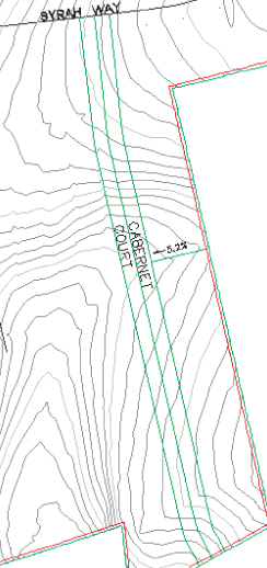
Figure 16.8 The completed alignment with offsets in place

16.8
Keep this drawing open to use in the next portion of the exercise.
If you click the alignment now, you will select the feature line that is stacked on top of the alignment. The feature line created by the alignment will not have any grips available. This is because the feature line is dynamically linked to the design profile along the alignment and can't be modified. If either the alignment or the profile changes, the dynamic feature line will automatically update. Simply repeat the preceding procedure to create new offsets if needed. These three feature lines can be included in a new surface definition as breaklines, as discussed in Chapter 4.
Because dynamically linked auto feature line objects are slightly different, you'll look at them in this next portion of the exercise.
15. Pan or zoom to view the feature line along the Cabernet Court alignment.
16. Select the auto feature line created from alignment to activate the Feature Line contextual tab.

UnFigure

17. From the Feature Line contextual tab ⇒ Modify panel, choose Feature Line Properties to display the Feature Line Properties dialog, as shown in Figure 16.9.

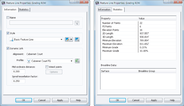
Figure 16.9 The Information tab (left) and Statistics tab (right) of the Feature Line Properties dialog for an alignment-based feature line

16.9
The information displayed on the Information tab is unique to the dynamic feature line, and you still have some level of control over the linking options.
18. On the Information tab, uncheck the Dynamic Link option and click OK to dismiss the Feature Line Properties dialog.
Notice the grips appear; they weren't previously visible when the feature line was dynamically linked. The dynamic relationship between the feature line and the alignment has been severed.
19. With the feature line still selected, from the Feature Line contextual tab ⇒ Modify panel, choose Feature Line Properties and notice the Dynamic Link options have disappeared.
Once the dynamic link is severed, it cannot be reinstated.
20. Click OK to dismiss the Feature Line Properties dialog and press Esc to deselect the feature line.
21. Select the two feature lines offset from the alignment feature line.
Notice that with two feature lines selected the Feature Line contextual tab still appears but the panels are limited.

UnFigure

22. With the feature lines still selected, from the Feature Line contextual tab ⇒ Modify panel, choose Apply Feature Line Styles to display the Apply Feature Line Style dialog.
23. Select the Grading Ditch style from the Style drop-down list and click OK to dismiss the dialog
24. Press Esc to deselect the feature lines.

Using Styles with Feature Line Objects
Many people don't see much advantage in using styles with feature line objects, but there is one major benefit: linetypes. Zoom in on the feature lines on either side of the alignment, and you'll see the Grading Ditch style has a dashed linetype. 3D polylines do not display linetypes, but feature lines do. If you need to show the linetypes in your grading, feature line styles are your friend.

When this exercise is complete, you may close the drawing. A saved copy of this drawing is available from the book's web page with the filename SteppedOffset_FINISHED.dwg or SteppedOffset_METRIC_FINISHED.dwg.

Now that you've created a couple of feature lines, you'll edit and manipulate them some more.

Editing Feature Line Information

From the Feature Line contextual tab, several more commands can be found on the Modify panel, as shown in Figure 16.10, that are worth examining before you get into editing objects.

Figure 16.10 The Modify panel on the Feature Line contextual tab

16.10

The Modify panel of the Feature Line contextual tab provides commands for editing various properties of the feature line, the feature line style, and the feature line geometry as follows:

UnFigure

Feature Line Properties

The top half of the Feature Line Properties tool is a button that will access the Feature Line Properties dialog. The Feature Line Properties dialog has two tabs: Information and Statistics, as shown previously in Figure 16.9. The Information tab of the Feature Line Properties dialog allows you to edit the name or feature line style. The Statistics tab of the Feature Line Properties dialog allows you to access various physical properties such as minimum and maximum grade.

The bottom half of the Feature Line Properties tool is a drop-down menu containing two commands:

Feature Line Properties

This command accesses the same Feature Line Properties dialog as discussed earlier when you click the button.

Edit Feature Line Style

This command is used to access various display characteristics of the feature line such as color and linetype. Feature line styles will be discussed further in Chapter 21, “Object Styles.”

UnFigure

Edit Geometry

The Edit Geometry toggle opens the Edit Geometry panel on the Feature Line contextual tab (see Figure 16.11). This panel will remain open until the Edit Geometry button is toggled off (it's highlighted when toggled on). The Edit Geometry panel will be discussed later in this section.

Figure 16.11 The Edit Geometry panel on the Feature Line contextual tab

16.11

UnFigure

Edit Elevations

The Edit Elevations toggle opens the Edit Elevations panel on the Feature Line contextual tab (see Figure 16.12). This panel will remain open until the Edit Elevations button is toggled off (it's highlighted when toggled on). The Edit Elevations panel will be discussed later in this chapter in the “Editing Feature Line Elevations” section.

Figure 16.12 The Edit Elevations panel on the Feature Line contextual tab

16.12

UnFigure

Add To Surface As Breakline

The Add To Surface As Breakline tool allows you to select a feature line or feature lines to add to a surface as breaklines. Once feature lines are added to the surface, they will be listed as a Breakline Set in the Definition branch of the surface in Prospector.

UnFigure

Apply Feature Line Names

The Apply Feature Line Names tool allows you to change a series of feature lines en masse based on a new naming template. This tool can be helpful when you want to rename a group or just assign names to feature line objects. This tool cannot be used on an auto feature line that is dynamically linked to an alignment and profile.

UnFigure

Apply Feature Line Styles

The Apply Feature Line Styles tool allows you to change feature line objects and their respective styles en masse. Many users don't apply styles to their feature line objects because the feature lines are found in grading drawings, and not meant to be seen in construction documents. But if you need to make a global change, you can.

UnFigure

Move To Site

If you expand the Modify panel, you will notice two additional commands. The first command is Move To Site. This command allows you to associate the selected feature line with a new site.

UnFigure

Copy To Site

The other command in the extended Modify panel is Copy To Site. This command allows you to duplicate the selected feature with a new site while leaving the original feature line in its current site. The two feature lines do not remain dynamically linked.

UnFigure

Once the Feature Line contextual tab has been activated, the Quick Profile tool is available on the Launch Pad panel. The Quick Profile tool generates a temporary profile of the feature line based on user parameters found in the Create Quick Profiles dialog (Figure 16.13).

Figure 16.13 The Create Quick Profiles dialog

16.13

A few notes on this operation:

  • Civil 3D creates a temporary phantom alignment that will not display in Prospector as the basis for a quick profile. A unique alignment number is assigned to this alignment.
  • Panorama will display a message to tell you that a quick profile has been generated and reminds you that “this is a temporary object and will be deleted on save command or on exit from drawing.” You can close Panorama or move the Panorama palette out of the way if necessary.

Feature lines aren't the only things you can create a quick profile from. You can also create a quick profile for 2D or 3D lines or polylines, lot lines, survey figures, or even a series of points. When a quick profile is created from 3D objects, there is an additional option to draw the 3D entity profile.

The Edit Geometry and Edit Elevations toggles provide even more commands, which make them considerably more powerful than a standard 3D polyline. The Edit Geometry functions and the Edit Elevations functions are described in the next sections. While these sections reference the Edit Geometry and Edit Elevations panels of the Feature Line contextual tab, these panels are also available on the Modify tab. When used from the Modify tab, many of these commands can also be used to edit parcel lines, survey figures, 3D polylines, and 2D polylines, in addition to feature lines as discussed in the sections that follow.

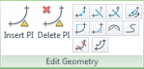
Editing feature-line geometry grading revisions often requires adding PIs, breaking apart feature lines, trimming, and performing other planar operations without destroying the vertical information. To access the commands for editing feature line horizontal information, select the feature line to access the Feature Line contextual tab and toggle on the Edit Geometry panel, as shown in Figure 16.14.

Figure 16.14 The Edit Geometry panel on the Feature Line contextual tab

16.14

The first two tools are designed to manipulate the PI points that make up a feature line:

UnFigure

Insert PI

The Insert PI tool allows you to insert a new PI, controlling both the horizontal and vertical design.

UnFigure

Delete PI

The Delete PI tool removes a PI. The feature line will mend the adjoining segments if possible, attempting to maintain similar geometry.

The next few tools act like their AutoCAD® counterparts, but are specifically for use with feature lines since they understand that elevations are involved and will add PIs accordingly:

UnFigure

Break

The Break tool operates much like the AutoCAD Break command, allowing two feature lines to be created from one. Additionally, if a feature line is part of a surface definition, both new feature lines are added to the surface definition to maintain integrity. Elevations at the new PIs are assigned on the basis of an interpolated elevation.

UnFigure

Trim

The Trim tool operates much like the AutoCAD Trim command, trimming a feature line and adding a new end PI on the basis of an interpolated elevation.

UnFigure

Join

The Join tool creates one feature line from two, making editing and control easier. You can set the tolerance distance from the settings associated with the Join tool on the Settings tab of Toolspace by doing the following:

1. Expand the Grading ⇒ Commands branch.
2. Right-click JoinFeatures and select Edit Command Settings.
3. In the Edit Command Settings – JoinFeatures dialog, expand the Feature Line Join property to change the tolerance.

UnFigure

Reverse

The Reverse tool changes the direction of a feature line. This will change the labeling.

Edit Curve

UnFigure

The Edit Curve tool allows you to modify the radius that has been applied to a feature line object. Once the feature line is selected, the Edit Feature Line Curve dialog will display. This dialog will allow you to step through each of the curves along the feature line. For each curve you can modify the radius while viewing information on the curve length, chord length, and tangent length. There is also an option to maintain tangency.

UnFigure

Fillet

The Fillet tool inserts a curve at PIs along a feature line and will join feature lines sharing a common PI that are not actually connected.

The last few tools refine feature lines, making them easier to manipulate and use in surface building:

Fit Curve

UnFigure

The Fit Curve tool analyzes a number of elevation points and attempts to define a working arc through them all. This tool is often used when the corridor utilities are used to generate feature lines. These derived feature lines can have a large number of unnecessary PIs in curved areas. You can modify the tolerance and the minimum number of segments by entering O to select Options on the command line during the prompt, and display the Fit Curve Options dialog.

Alternatively you can set the default values for these options from the settings associated with the Fit Curve tool on the Settings tab of Toolspace by doing the following:

1. Expand the Grading ⇒ Commands branch.
2. Right-click FitCurveFeature and select Edit Command Settings.
3. In the Edit Command Settings – FitCurveFeature dialog, expand the Feature Line Fit Curve property to change the tolerance and specify the minimum number of segments.

Smooth

UnFigure

The Smooth tool takes a series of disjointed feature line segments and creates a best-fit curve. This tool is great for creating streamlines or other natural terrain features that are known to curve, but there's often not enough data to fully draw them that way. You can also straighten previously-smoothed feature lines on the Modify tab ⇒ Edit Geometry panel by choosing the Smooth command. Notice that the Smooth command accessed through the Feature Line contextual tab does not give you the straighten option.

Weed

UnFigure

The Weed tool allows the user to remove elevation points and PIs on the basis of various criteria. Once you select the feature line or multiple feature lines, or a partial feature line, the Weed Vertices dialog will display. This dialog will allow you to weed based on any combination of angle, grade, or length; in addition you can remove points based on their 3D distance between one another. At the bottom of the Weed Vertices dialog it states how many of the total number of vertices will be weeded. This is great for cleaning up corridor-generated feature lines as well.

Similar to the Join and Fit Curve tools, you can set the default settings associated with the Weed command on the Settings tab of Toolspace by doing the following:

1. Expand the Grading ⇒ Commands branch.
2. Right-click WeedFeatures and select Edit Command Settings.
3. In the Edit Command Settings – WeedFeatures dialog, expand the Feature Line Weed property to change the various values.

UnFigure

Stepped Offset

As discussed in detail earlier, the Stepped Offset tool allows offsetting in a horizontal and vertical manner, making it easy to create stepped features such as stairs or curbs.

By using these controls, it's easier to manipulate the design elements of a typical site while still using feature lines for surface design. In this exercise, you manipulate a number of feature lines that were created by corridor operations:

1. Open the FeatureLineGeometry.dwg or FeatureLineGeometry_METRIC.dwg file.
This drawing is a continuation of the SteppedOffset.dwg file but has been populated with some more feature lines.
2. Select the southern east-west feature line (which is the offset from the Syrah Way alignment feature line), as shown in Figure 16.15.

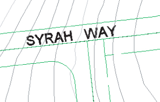
Figure 16.15 Picking the southern feature line on Syrah Way

16.15
3. From the Feature Line contextual tab ⇒ Modify panel, choose Edit Geometry to toggle on the Edit Geometry panel.

UnFigure

4. Click the Break tool.
5. At the Select an object to break: prompt, select the lower feature line again.
6. At the Specify second break point or [First point]: prompt, enter F SoftEnter to pick the first point of the break.
7. At the Specify first break point: prompt, using an Intersection Osnap select the intersection of the east-west feature line to the south of Syrah Way, and the north-south feature line to the west of Cabernet Court, as shown in Figure 16.16.

Figure 16.16 Using the Intersection object snap to select a point

16.16
8. At the Specify second break point: prompt, using a Nearest Osnap select a point on the east-west feature line to the east of the eastern north-south feature line, leaving a gap, as shown in Figure 16.17.

Figure 16.17 The feature line after executing the Break command

16.17
9. Select the right east-west feature line that was previously broken and notice the large number of grips.

UnFigure

10. From the Feature Line contextual tab ⇒ Edit Geometry panel, click the Weed tool.
11. At the Select a feature line, 3d polyline or [Multiple Partial]: prompt, select the feature line again.
The Weed Vertices dialog will be displayed.
12. Change the Angle to 0.2 and the Grade to 0.25%.
Watch the glyphs on the feature line and notice the number of vertices that will be removed from the feature line. Additionally, the glyphs on the feature line itself will change from green to red to reflect nodes that will be removed under the current setting, as shown in Figure 16.18.

Figure 16.18 Feature lines to be weeded

16.18
13. Click OK to complete the command and dismiss the Weed Vertices dialog.
14. Using a standard AutoCAD Extend command, extend the right east-west feature line to the eastern Cabernet Court offset feature line.
There is no unique feature line extending tool.
15. Select the left east-west feature line that was previously broken to activate the Feature Line contextual tab.

UnFigure

16. From the Feature Line contextual tab ⇒ Edit Geometry panel, click the Trim tool from the Edit Geometry panel.
A standard AutoCAD trim will not work in this case.
17. At the Select cutting edges: prompt, select the left east-west feature line as the cutting edge and press SoftEnter.
18. At the Select objects to trim: prompt, select the western Cabernet Court offset feature line above the cutting edge and press SoftEnter to end the command and review the results (see Figure 16.19).

Figure 16.19 The left east-west feature line trimmed

16.19

UnFigure

19. From the Feature Line contextual tab ⇒ Edit Geometry panel, click the Join tool.
20. At the Select the connecting feature line, polyline or 3d polyline or [Multiple]: prompt, select the left north-south feature line and press SoftEnter.
Notice the grips and that the two feature lines have been joined.

UnFigure

21. From the Feature Line contextual tab ⇒ Edit Geometry panel, click the Fillet tool.
22. At the Specify corner or [All Join Radius]: prompt, enter R SoftEnter to adjust the radius value.
23. At the Specify radius: prompt, enter 15 SoftEnter (or 4.5 SoftEnter for metric users).
24. Move your cursor toward the join corner just created until the glyph appears and select near the glyph to fillet the two feature lines.
25. Press SoftEnter to end the command.

UnFigure

26. From the Feature Line contextual tab ⇒ Edit Geometry panel, click the Edit Curve tool
27. At the Select feature line curve to edit or [Delete]: prompt, select the curve you just create.
The Edit Feature Line Curve dialog opens, as shown in Figure 16.20.

Figure 16.20 The Edit Feature Line Curve dialog

16.20
28. Enter a Radius value of 34 SoftEnter (or 10 SoftEnter for metric users), and click OK to close the dialog.
29. Press SoftEnter to end the command. The drawing should now look similar to Figure 16.21.

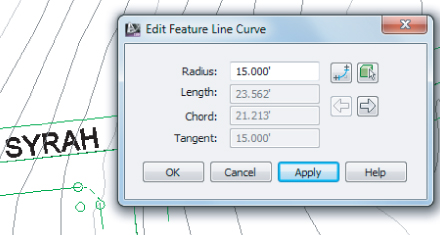
Figure 16.21 Filleted feature lines

16.21

When this exercise is complete, you may close the drawing. A saved copy of this drawing is available from the book's web page with the filename FeatureLineGeometry_FINISHED.dwg or FeatureLineGeometry_METRIC_FINISHED.dwg.


Modifying Feature Lines
When modifying the radius of a feature line curve, it's important to remember that you must have enough tangent feature line on either side of the curve segment to make a curve fit, or the program will not make the change. In that case, tweak the feature line on either side of the arc until there is a mathematical solution.
Sometimes it is necessary to use the Weed Vertices tool to remove vertices, and create enough room to fillet feature lines. In some cases, it may be necessary to plan ahead when creating feature lines to ensure that vertices will not be placed too closely together.

Editing Feature Line Elevations

To access the commands for editing feature line elevation information, from the Feature Line contextual tab ⇒ Modify panel, choose the Edit Elevations toggle to open the Edit Elevations panel.

UnFigure

The first tool in this panel is the Elevations Editor, which will activate a palette in Panorama to display and edit station, elevation, length, and grade information about the feature line selected in a tabular grid format. When you are in a row in the Elevation Editor, the corresponding point will be shown with a temporary marker on the plan.

Quite a few tools are available to modify and manipulate feature lines. You won't use all of the tools, but at least you'll have some concept of what is available. The next exercises give you a look at a few of them. In this first exercise, you'll take a brief look at the Grading Elevation Editor tools:

1. Open the EditingFeatureLineElevations.dwg or EditingFeatureLineElevations_METRIC.dwg file.
This drawing contains a sample layout with some curb and gutter work.
2. Select the feature line representing the left flowline of the curb and gutter area to activate the Feature Line contextual tab.
3. On the Feature Line contextual tab ⇒ Edit Elevations panel, choose the Elevation Editor tool
The Grading Elevation Editor in Panorama will open, as shown in Figure 16.22.

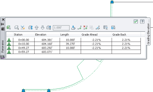
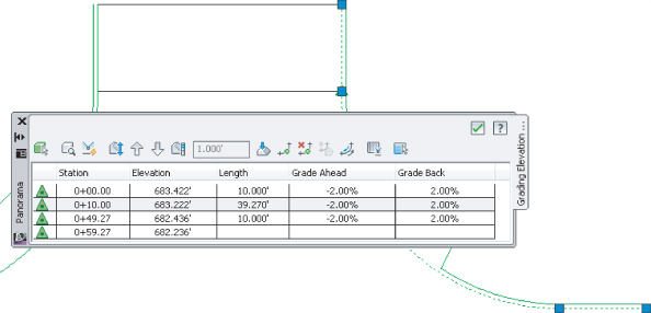
Figure 16.22 The Grading Elevation Editor

16.22
In the far left column of the Grading Elevation Editor is a series of symbols; these are the same glyph symbols used on the feature line grips. A triangular symbol denotes a PI, and a circular symbol denotes an elevation point. In this example you don't have any elevation points.
4. Click in the Grade Ahead column for the first PI at Station 0+00.00 (or 0+000.00).
It's hard to see in the images, but as a row is selected in the Grading Elevation Editor, the PI or the elevation point that was selected will be highlighted on the screen with a small glyph.
You can use the Grading Elevation Editor to make changes to the Station, Elevation, Length, Grade Ahead, and Grade Back settings. The exception is that you cannot edit stationing for primary geometry points, as indicated by the triangle glyph in the Grading Elevation Editor.
Across the top of the Grading Elevation Editor are multiple tools that will be used as you edit the data in the table:

UnFigure

Select

Clicking the Select tool allows you to select the feature line on the screen for editing in the Grading Elevation Editor.

UnFigure

Zoom To

The Zoom To tool will do exactly as it says. If you have a station highlighted in the Panorama and select the Zoom To tool, your plan view will be zoomed to that station on the feature line on the screen.

UnFigure

Quick Profile

The Quick Profile tool will generate a temporary profile based on the feature line selected. This is the same tool discussed earlier that was available on the Feature Line contextual tab ⇒ Launch Pad panel. The Create Quick Profiles dialog will open, allowing you to select what surface(s) you wish to display, as well as what profile view style and 3D entity profile you want.

UnFigure

Raise/Lower

Clicking the Raise/Lower tool will activate the Set Increment text box. This allows you to raise or lower selected elevation points, or if no elevation points are selected, it will raise or lower the entire feature line elevation points by the amount displayed in the text box.

UnFigure

Raise Incrementally and Lower Incrementally

The Raise Incrementally/Lower Incrementally tools will raise or lower the elevation point or points by the amount listed in the Set Increment text box.

Set Increment

UnFigure

The Set Increment tool works in tandem with the text box. You can enter a value that will be used by other tools for raising or lowering elevation point or points.

UnFigure

Flatten Grade Or Elevations

The Flatten Grade Or Elevations tool will make all of the selected elevation points the value of the first selected point, or if no points are selected, the value of the first entry in the cells. When this tool is selected, the Flatten dialog will open asking if you want to flatten by constant elevation or by constant grade.

UnFigure

Insert Elevation Point

The Insert Elevation Point will let you select a spot on the feature line, and will create an intermediate elevation point. The Insert PVI dialog will open, allowing you to fine-tune the station and enter an elevation.

UnFigure

Delete Elevation Point

The Delete Elevation Point will delete a point or points that are highlighted in the Grading Elevations Editor. Note that this tool will allow you to delete only intermediate points.

UnFigure

Elevations From Surface

Clicking the Elevations From Surface tool will open the Select Surface dialog if there are multiple surfaces to choose from. If you have an elevation point or points selected, it will affect only those points, or if nothing is selected it will use all elevation points and drape them onto the selected surface.

UnFigure

Reverse The Direction

The Reverse The Direction tool will do exactly as it says; it will reverse the direction of the feature line, thus changing the stationing and the grade ahead/grade back directions.

UnFigure

Show Grade Breaks Only

The Show Grade Breaks Only tool is a toggle (click, it's on and click, it's off) that will display only the rows where the grade varies or breaks on the feature line.

UnFigure

Unselect All Rows

The Unselect All Rows tool does exactly as it says; it will deselect any rows that have been highlighted for editing.

5. Click the green check mark in the upper-right corner to dismiss the Panorama.

Using the Grading Elevation Editor is the most basic way to manipulate elevation information. Keep this drawing open for use in the next exercise.

More Feature Line Elevation Editing Tools

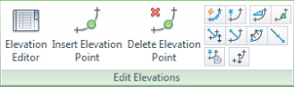
To access the commands for editing feature line elevation information, select the feature line to access the Feature Line contextual tab and toggle on the Edit Elevations panel as shown in Figure 16.23. Many of the tools in the Elevation Editor may seem redundant from the Grading Elevation Editor tools just discussed, but they are placed here for ease of use.

Figure 16.23 The Edit Elevations panel on the Feature Line contextual tab

16.23

Moving across the panel beyond the Elevation Editor tool, which was just discussed, you find the following tools for modifying or assigning elevations to feature lines:

UnFigure

Insert Elevation Point

The Insert Elevation Point tool inserts an elevation point at the point selected or multiple elevation points at a specified increment. Note that elevation points can control only elevation information; it does not act as a horizontal control point.

UnFigure

Delete Elevation Point

The Delete Elevation Point tool deletes the selected elevation point; the points on either side then become connected linearly on the basis of their current elevations. You can also delete all elevation points on a feature line with this command.

UnFigure

Quick Elevation Edit

The Quick Elevation Edit tool allows you to use onscreen cues to set elevations and slopes quickly between PIs on any feature lines.

UnFigure

Edit Elevations

The Edit Elevations tool steps through the selected feature line, much like working through a polyline edit at the command line, allowing you to change elevations and grades or insert, move, and delete elevation points.

UnFigure

Set Grade/Slope Between Points

The Set Grade/Slope Between Points tool sets a continuous slope along the feature line between selected points.

UnFigure

Insert High/Low Elevation Point

The Insert High/Low Elevation Point tool places a new elevation point on the basis of two picked points and the forward and backward slopes. This calculated point is simply placed at the intersection of two vertical slopes.

UnFigure

Raise/Lower By Reference

The Raise/Lower By Reference tool allows you to adjust a feature line elevation based on a given slope from another location. This relationship isn't dynamic!

UnFigure

Set Elevation By Reference

The Set Elevation By Reference tool sets the elevation of a selected point along the feature line by picking a reference point, and then establishing a relationship to the selected feature line point. This relationship isn't dynamic!

UnFigure

Adjacent Elevations By Reference

The Adjacent Elevations By Reference tool allows you to adjust the elevation on a feature line by coming at a given slope or delta from another point or feature line point. This relationship isn't dynamic!

UnFigure

Grade Extension By Reference

The Grade Extension By Reference tool allows you to apply the same grades to different feature lines across a gap. For example, you might use this tool along the back of curbs at locations such as driveways or intersections. This relationship isn't dynamic!

UnFigure

Elevations From Surface

The Elevations From Surface tool sets the elevation at each PI and elevation point on the basis of the selected surface. It will optionally add elevation points at any point where the feature line crosses a surface TIN line.

UnFigure

Raise/Lower

The Raise/Lower tool simply moves the entire feature line in the z direction by an amount entered at the command line.

Some of the relative elevation tools are a bit harder to understand, so you'll look at them in our next exercise and see how they function in some basic scenarios:

1. If not opened for the previous exercise, open the EditingFeatureLineElevations.dwg or EditingFeatureLineElevations_METRIC.dwg file.
This drawing contains a sample layout with some curb and gutter work.
2. Zoom to the ramp shown on the left-hand side of the intersection.
3. Select the feature line describing the ramp at the left-hand side to activate the Feature Line contextual tab.
4. If the Edit Elevations panel isn't already displayed, from the Feature Line contextual tab ⇒ Modify panel choose Edit Elevations.
5. From the Feature Line contextual tab ⇒ Edit Elevations panel, choose the Elevation Editor tool to display the Grading Elevation Editor tab in Panorama.
Notice that the entire feature line is at elevation 0.000′ (0.000 m).
6. Click the green check mark in the upper right to close the Panorama.
7. Press Esc to deselect the left ramp feature line.
8. Select the feature line representing the flowline of the curb and gutter area at the left-hand side to activate the Feature Line contextual tab.

UnFigure

9. From the Feature Line contextual tab ⇒ Edit Elevations panel, choose the Adjacent Elevations By Reference tool.
10. At the Select object to edit or [Name]: prompt, select the left ramp feature line.
Civil 3D will display a number of glyphs and lines to represent what points along the flowline it is using to establish elevations from.
11. At the Specify elevation difference or [Grade Slope]: prompt, enter 0.5 SoftEnter (or 0.15 SoftEnter for metric users) at the command line to update the ramp elevations.
12. Press SoftEnter again to end the command.
13. Press Esc to deselect the gutter feature line, and then select the ramp feature line.
14. From the Feature Line contextual tab ⇒ Edit Elevations panel, choose the Elevation Editor tool to display the Grading Elevation Editor tab in Panorama.
Notice that the PIs now each have an elevation, as shown in Figure 16.24.

Figure 16.24 Completed editing of the curb ramp feature line

16.24
15. Click the green check mark in the upper right of the Panorama to dismiss it.
16. Save and keep this drawing open for the next portion of the exercise.
Next, you'll need to extend the grade along the line representing the flowline of the curb and gutter area on the left of the screen to determine the elevation to the south of your intersection on the right of the screen. You'll use the Grade Extension By Reference tool in the following portion of the exercise to accomplish this.
17. Select the feature line representing the flowline of the curb and gutter area on the left side of the drawing.

UnFigure

18. From the Feature Line contextual tab ⇒ Edit Elevations panel, choose the Grade Extension By Reference tool.
19. At the Select reference segment: prompt, select the left flowline feature line again (see Figure 16.22).
This tool will evaluate the feature line as if it were three separate components (two lines and an arc). Because you are extending the grade of the flowline to the east and across the intersection, it is important to select the tangent segment, as shown in Figure 16.25. If you select the wrong segment, press Esc and then select the correct segment.

Figure 16.25 Selecting the flowline of the curb and gutter section at the left

16.25
20. At the Select object to edit or [Name]: prompt, select the line representing the flowline of the curb and gutter area to the right of your screen, as shown in Figure 16.26.

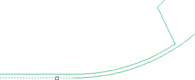
Figure 16.26 Selecting the flowline at the right side of the tangent segment

16.26
21. At the Specify point: prompt, pick the PI at the left side of the tangent, as shown in Figure 16.27.

Figure 16.27 Selecting the PI at the left side of the tangent segment representing the flowline of the curb and gutter section

16.27
22. At the Specify grade or [Slope Elevation Difference] <-2.21>: prompt, press SoftEnter to accept the default value of -2.21 (this is the grade of the flowline of the curb and gutter section to the left).
23. Press SoftEnter to end the command, and press Esc to cancel grips.
24. Select the feature line representing the flowline of the curb and gutter section to the right of your screen to enable grips.
25. Move your cursor over the top of the PI, as shown in Figure 16.28, but do not click.

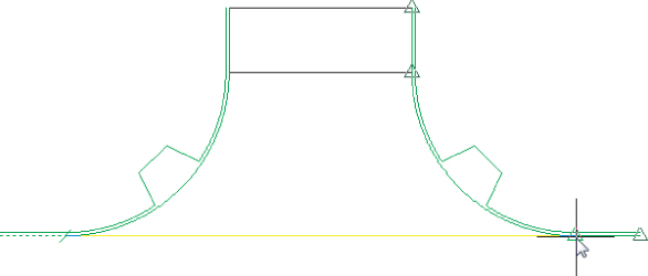
Figure 16.28 The x-, y-, and z-coordinates of the PI displayed on the status bar

16.28
Your cursor will automatically snap to the grip, and the grip will change color. Notice that the elevation of the PI is displayed on the status bar, as shown in Figure 16.28. This is a quick way to check elevations of vertices when modeling terrain.
If your coordinates are not displayed,
a. Enter the AutoCAD command COORDS.
b. Set the value to 1 to display them.
Leave this drawing open for the last portion of the exercise.
With the elevation of a single point determined, the grade of the feature line representing the curb and gutter section can be modified to ensure positive water flow. In the last portion of the exercise, you'll use the Set Grade/Slope Between Points tool to modify the grade of the feature line.
26. Select the feature line representing the flowline of the curb and gutter section to the right of your screen.

UnFigure

27. From the Feature Line contextual tab ⇒ Edit Elevations panel, choose the Set Grade/Slope Between Points.
28. At the Specify the start point: prompt, select the PI as shown previously in Figure 16.27.
The elevation of this point has been established and will be used as the basis for grading the entire feature line.
29. At the Specify elevation: prompt, press SoftEnter to accept the default value.
This is the current elevation of the PI as established earlier.
30. At the Specify the end point: prompt, select the PI as shown in Figure 16.29.

Figure 16.29 Specifying the PI to establish the elevation at the flowline of the curb and gutter section

16.29
31. At the Specify grade or [Slope Elevation Difference]: prompt, enter 2 SoftEnter to set the grade between the points at 2 percent. Do not end the command.
32. At the Select object: prompt, select the feature line representing the flowline of the curb and gutter section to the right again.
33. At the Specify the start point: prompt, pick the PI (shown earlier in Figure 16.27) again.
34. At the Specify elevation: prompt, press SoftEnter to accept the default value.
This is the current elevation of the PI as established earlier.
35. When you see the Specify the end point: prompt, pick the PI at the far bottom right along the feature line currently being edited.
36. At the Specify grade or [Slope Elevation Difference]: prompt, enter -2 SoftEnter to set the grade between the points at negative 2 percent.
37. Press SoftEnter to end the command but do not cancel grips.
38. Select the Elevation Editor tool from the Edit Elevations panel to display Panorama.
Notice the values in both the Grade Ahead and Grade Back columns, as shown in Figure 16.30.

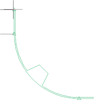
Figure 16.30 The grade of the feature line set to 2 percent

16.30
To finish the intersection, you could use the Adjacent Elevations By Reference tool again to define the right ramp.

When this exercise is complete, you may close the drawing. A saved copy of this drawing is available from the book's web page with the filename EditingFeatureLineElevations_FINISHED.dwg or EditingFeatureLineElevations_METRIC_FINISHED.dwg.

Using these feature line elevation editing tools, the possibilities are endless. In using feature lines to model proposed features, you are limited only by your creative approach. You've seen many of the tools in action, so you can now put a few more of them together and grade a pond.

Draining the Pond

You need to use a combination of feature line tools and options to pull your pond together, and get the most flexibility should you need to update the bottom area or manipulate the pond's general shape. In this exercise, you will use feature lines to design your pond:

1. Open the PondDrainageDesign.dwg or PondDrainageDesign_METRIC.dwg file.
The engineer gave us a bit more information about the pond design, as shown in Figure 16.31.

Figure 16.31 A polyline at the bottom of pond and a polyline for the outlet channel

16.31
There is a feature line depicting the pond bottom, which has been assigned a constant elevation of 0, and a feature line depicting the outlet channel, which has been assigned elevations from the existing surface. In addition, the engineer has provided us with the Inflow and Outflow locations.
2. Select the pond basin feature line to activate the Feature Line contextual tab.
3. From the Feature Line contextual tab ⇒ Edit Elevation panel (toggle it on if needed), choose the Insert Elevation Point tool.
4. Use the Center Osnap to insert the elevation points in the center of each circle.
5. Enter 779.5′ (237.6 m) as the elevation of each inflow, and accept the default elevation at the outflow.
You will change the elevation at the outflow in a moment.
6. Press SoftEnter to end the command, and press Esc to cancel grips.
7. From the Home tab ⇒ Create Design panel, choose Feature Line ⇒ Create Feature Lines From Objects.
8. Pick the polyline that represents the pilot channel from the northwestern inflow to the outflow channel centerline and press SoftEnter.
The Create Feature Lines dialog appears.
9. Verify that Site is set to Pond and that the Assign Elevations check box is unchecked, and click OK.
Because this feature line was created in the same site as the bottom of the pond, the elevation of the PI at the southernmost inflow will reset to match the elevation of the endpoint of the pilot channel.
10. Select the feature line you just created representing the pilot channel to activate the Feature Line contextual tab.
11. From the Feature Line contextual tab ⇒ Edit Geometry panel (toggle it on if needed), choose the Fillet tool.
12. At the Specify corner or [All Join Radius]: prompt, enter R SoftEnter, and enter 25 SoftEnter (7.5 SoftEnter for metric users) for the radius.
13. Select the corner of the feature line in the center of the pond to fillet all PIs.
14. Press SoftEnter to exit the Fillet command.
15. From the Feature Line contextual tab ⇒ Edit Elevations panel, choose the Set Grade/Slope Between Points tool.
16. At the Specify the start point: prompt, select the PI at the inflow.
17. At the Specify elevation: prompt, enter 779.5 SoftEnter (237.6 SoftEnter for metric users) to set this elevation.
18. At the Specify the end point: prompt, select the other end of the feature line, as shown in Figure 16.32.

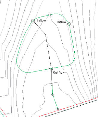
Figure 16.32 Setting grade between points

16.32
All the PIs will highlight, and Civil 3D will display the total length, elevation difference, and average slope at the command line.
19. At the Specify grade or [Slope Elevation Difference]: prompt, press SoftEnter again to accept the grade as shown.
This completes a linear slope from one end of the feature line to the other, ensuring drainage through the pond and outfall structure.
20. Press SoftEnter to end the command.
21. Press Esc to cancel grips.
22. Select the feature line representing the bottom of the pond to activate the Feature Line contextual tab.
23. From the Feature Line contextual tab ⇒ Edit Elevations panel, choose the Elevation Editor tool display the Grading Elevation Editor in Panorama.
24. Click in the Station cells in the Grading Elevation Editor to highlight and ascertain the elevation at the outfall, as shown in Figure 16.33.

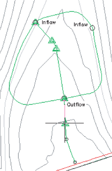
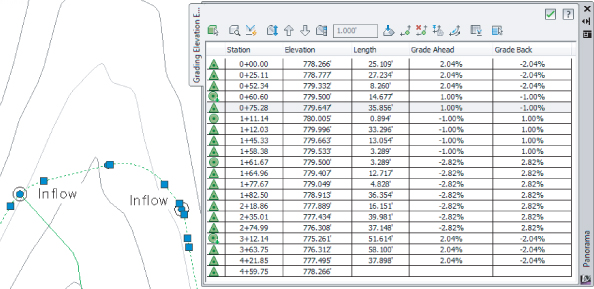
Figure 16.33 The Grading Elevation Editor

16.33
In this case, the elevation is 775.261′ (236.302 m). When done observing the elevations, you may close the Panorama.
25. From the Feature Line contextual tab for the feature line representing the bottom edge of the pond, choose the Set Grade/Slope Between Points tool from the Edit Elevations panel.
26. At the Specify the start point: prompt, move your cursor over the PI at the northwestern inflow and select it.
27. Press SoftEnter to accept the default elevation.
28. At the Specify the end point: prompt, move your cursor counterclockwise and select the PI at the outflow.
29. Press SoftEnter to accept the grade.
This sets the elevations between the one inflow and the outflow PIs to all fall at the same grade.
30. At the Select object: prompt, select the feature line representing the pond bottom again.
31. Repeat steps 26–29 for the PI on the other inflow (located on the northeast side of the pond) and the outflow located clockwise from the start point.
They will set the elevations between the other inflow and the outflow to a constant slope.
32. When done, press SoftEnter to end the command.
The entire outline of the pond bottom is graded except the area between the two inflows, as shown in Figure 16.34.

Figure 16.34 Zero elevation remains between the two inflows

16.34
Because you want to avoid a low spot, you'll now force a high point:
33. From the Feature Line contextual tab for the pond feature line, choose the Insert High/Low Elevation Point tool from the Edit Elevations panel.
34. At the Specify the start point: prompt, select the PI at the northwestern inflow.
35. At the Specify the end point: prompt, select the PI at the northeastern inflow as the endpoint.
36. At the Specify grade ahead or [Slope]: prompt, enter 1.0 SoftEnter.
37. At the Specify grade back or [Slope]: prompt, enter 1.0 SoftEnter as the grade behind. A new elevation point will be created, as shown in Figure 16.35.

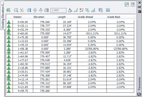
Figure 16.35 Using the Grade Back column in the Grading Elevation Editor

16.35
38. When done, press SoftEnter to end the command and press Esc to deselect the feature line.

When this exercise is complete, you may close the drawing. A saved copy of this drawing is available from the book's web page with the filename PondDrainageDesign_FINISHED.dwg or PondDrainageDesign_METRIC_FINISHED.dwg.

By using all the tools in the Feature Lines toolbar, you can quickly grade elements of your design and pull them together. If you have difficulty getting all the elevations in this exercise to set as they should, slow down, and make sure you are moving your mouse in the right direction when setting the grades by slope. It's easy to get the calculation performed around the other direction—that is, clockwise versus counterclockwise. It helps to move your mouse along the feature line in the direction you want the slopes to be maintained. This procedure seems to involve a lot of steps, but it takes less than a minute in practice.

There are roughly 25 ways to modify feature lines using both the Edit Geometry and Edit Elevations panels of the Feature Line contextual tab. Take a few minutes and experiment with them to understand the options and tools available for these essential grading elements. By manipulating the various pieces of the feature line collection, it's easier than ever to create dynamic modeling tools that match the designer's intent.

Labeling Feature Lines

Though it's not common, feature lines can be stylized to reflect particular uses, and labels can be applied to help a reviewer understand the nature of the object being shown. In the next couple of exercises, you'll label a few critical points on your pond design to help you better understand the drainage patterns.

Feature lines do not have their own unique label styles, but instead share with general lines and arcs. You can learn more about label styles in Chapter 20, “Label Styles.” The templates that ship with Civil 3D contain styles for labeling segment slopes, so you'll label the grades of feature line segments in the following exercise:

1. Open the LabelingFeatureLines.dwg or LabelingFeatureLines_METRIC.dwg file.
2. From the Annotate tab ⇒ Labels & Tables panel, click the Add Labels button to display the Add Labels dialog.
3. In the Add Labels dialog, do the following:
a. Set the Feature drop-down to Line And Curve.
b. Set Label Type to Single Segment
c. Set Line Label Style to Grade Only.
d. Set Curve Label Style to Grade Only.
When complete, the dialog should look like Figure 16.36.

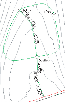
Figure 16.36 Adding feature line grade labels

16.36
4. Click the Add button.
5. At the Select point on entity: prompt, pick a few points along the pilot channel feature line (the feature line that goes across the bottom of the pond) tangents to create labels, as shown in Figure 16.37.

Figure 16.37 Feature line grade labels in the Imperial drawing

16.37

When this exercise is complete, you may close the drawing. A saved copy of this drawing is available from the book's web page with the filename LabelingFeatureLines_FINISHED.dwg or LabelingFeatureLines_METRIC_FINISHED.dwg.

Although it would be convenient to label the feature line elevations as well, there's no simple method for doing so. In practice, you would want to label the surface that contains the feature line as a component.

Grading Objects

Once a feature line is created, there are two main uses. One is to incorporate the feature line itself directly into a surface object as a breakline; the other is to create a grading object (referred to hereafter as simply a grading or gradings) using the feature line as a baseline. A grading consists of a baseline with elevation information, and a criteria set for projecting outward from that baseline based on distance, slope, or other criteria. These criteria sets can be defined and stored in grading criteria sets for ease of management. Finally, gradings can be stylized to reflect plan production practices or convey information such as cut or fill.

In this section, you'll use a number of methods to create gradings, edit those gradings, and finally convert the grading group into a surface.

Creating Gradings

certobjective

Let's look at grading the pond as designed. In this section, you'll look at grading groups and then create the individual gradings within the group. Grading groups act as a collection mechanism for individual gradings, and let Civil 3D understand the daisy chain of individual gradings that are related and act in sync with each other.

One thing to be careful of when working with gradings is that they are part of a site. Any feature line within that same site will react with the feature lines created by the grading. For that reason, the exercise drawing has a second site called Pond Grading to be used for just the pond grading.

1. Open the GradingThePond.dwg or GradingThePond_METRIC.dwg file.
2. Select the feature line representing the bottom of the pond to activate the Feature Line contextual tab.
3. From the Feature line contextual tab ⇒ expanded Modify panel, choose Move To Site to display the Move To Site dialog.
4. On the Information tab of the Site Properties dialog, set Name to Pond Grading and click OK.
5. Set the Destination Site drop-down list to the new site named Pond Grading and click OK.
This will avoid interaction between the pond banks and the pilot channel you laid out earlier.

UnFigure

6. With the feature line still selected, on the Feature Line contextual tab ⇒ Launch Pad panel, choose Grading Creation Tools.
The Grading Creation Tools toolbar, shown in Figure 16.38, appears. The left section is focused on settings, the middle on creation, and the right on editing.

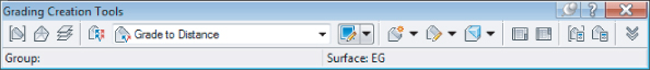
Figure 16.38 The Grading Creation Tools toolbar

16.38

UnFigure

7. On the Grading Creation Tools toolbar, click the Set The Grading Group tool to the far left of the toolbar to display the Site dialog.
8. Choose the Pond Grading site and click OK.
The Create Grading Group dialog is displayed.
9. Enter Pond Grading in the Name text box, as shown in Figure 16.39, and click OK.

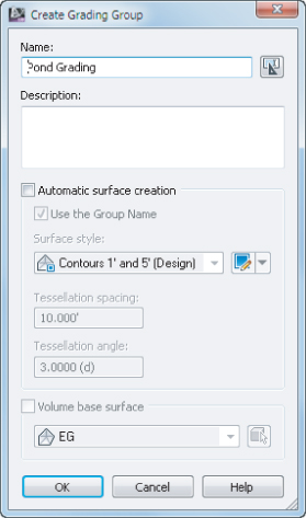
Figure 16.39 Assign the name Pond Grading in the Create Grading Group dialog.

16.39
You'll revisit the surface creation options in a bit.

UnFigure

10. On the Grading Creation Tools toolbar, click the Select Target Surface tool located next to the Select Grading Group tool to display the Select Surface dialog.
11. Select the EG surface and click OK.

UnFigure

12. On the Grading Creation Tools toolbar, verify that the Grading Criteria is set to Grade To Elevation and click the Create Grading tool, or click the down arrow next to the Create Grading tool and select Create Grading, as shown in Figure 16.40.

Figure 16.40 Creating a grading using the 3:1 To Elevation criteria

16.40
13. At the Select the feature: prompt, select the pond outline.
If you get a dialog asking you to weed the feature line,
a. Select the Weed The Feature Line option.
b. Click OK in the Weed Vertices dialog.
14. At the Select the grading side: prompt, pick a point on the outside of the pond to indicate the direction of the grading projections.
15. At the Apply to entire length? [Yes No]: prompt, enter Y SoftEnter to apply the grading to the entire length of the pond outline.
16. Enter 784 SoftEnter (or 239 SoftEnter for metric users) at the command line as the target elevation.
17. At the Cut Format [Grade Slope]: prompt, enter S SoftEnter.
18. At the Cut Slope: prompt, enter 3 SoftEnter for a 3 horizontal to 1 vertical slope.
19. At the Fill Format [Grade Slope]: prompt, enter S SoftEnter.
20. At the Fill Slope: prompt, enter 3 SoftEnter for a 3 horizontal to 1 vertical slope.
The first grading is complete. The lines onscreen are part of the Grading style.
21. Press Esc to end the command.
22. On the Grading Creation Tools toolbar, verify that the Grading Criteria is set to Grade To Distance, and click the Create Grading tool.
23. At the Select the feature: prompt, select the upper boundary of the grading made in step 20, as shown in Figure 16.41.

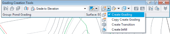
Figure 16.41 Creating a daisy chain of gradings

16.41
24. At the Apply to entire length? [Yes/No]: prompt, enter Y SoftEnter to apply to the whole length. Notice that you did not have to select a side, because there is already a grading object on one side of the selected feature line.
25. At the Specify distance: prompt, enter 10 SoftEnter (3 SoftEnter for metric users) for the target distance to build the safety ledge.
26. At the Format [Grade Slope]: prompt, enter G SoftEnter.
27. At the Grade: prompt, enter 0 SoftEnter.
28. Press Esc to end the command.
29. On the Grading Creation Tools toolbar, verify that Grading Criteria is set to Grade To Surface, and click the Create Grading tool.
30. At the Select the feature: prompt, select the outer edge of the safety ledge just created.
31. At the Apply to entire length? [Yes/No]: prompt, enter Y SoftEnter to apply to the whole length.
32. At the Cut Format [Grade Slope]: prompt, enter S SoftEnter.
33. At the Cut Slope: prompt, enter 3 SoftEnter for a 3 horizontal to 1 vertical slope.
34. At the Fill Format [Grade Slope]: prompt, enter S SoftEnter.
35. At the Fill Slope: prompt, enter 3 SoftEnter for a 3 horizontal to 1 vertical slope.
36. Press Esc to end the command.
Your drawing should look similar to Figure 16.42.

Figure 16.42 Complete pond feature line grading

16.42

When this exercise is complete, you may close the drawing. A saved copy of this drawing is available from the book's web page with the filename GradingThePond_FINISHED.dwg or GradingThePond_METRIC_FINISHED.dwg.

Each piece of this pond is tied to the next, creating a dynamic model of your pond design on the basis of the designer's intent. What if that intent changes? The next section describes editing the various gradings.

Editing Gradings

Once you've created a grading, you often need to make changes. A change can be as simple as changing the slope or changing the geometric layout. In this exercise, you'll make a simple change, but the concept applies to all the gradings you've created in your pond.

1. Open the EditingGrading.dwg or EditingGrading_METRIC.dwg file.

UnFigure

2. Pick one of the interior projection lines or the small diamond on the interior slope of the pond in order to select the grading object.
3. From the Grading contextual tab ⇒ Modify panel, choose the Grading Editor tool to display the Grading Editor in Panorama. If the correct grading object was selected in step 2, then at the top of Panorama it should state Criteria: Grade To Elevation.
4. Change the Fill Slope Projection and Cut Slope Projection both to 4. Note that after you click out of the cell, the software will change this to read as 4.00:1, as shown in Figure 16.43.

Figure 16.43 Editing the Cut and Fill Slope values

16.43
The grading may take a few seconds to update between edits.
5. Close Panorama.
Your display should look like Figure 16.44. (Compare this to Figure 16.42 if you'd like to see the difference.)

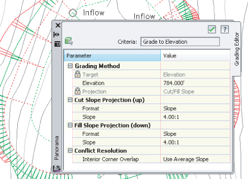
Figure 16.44 Completed grading edit

16.44

When this exercise is complete, you may close the drawing. A saved copy of this drawing is available from the book's web page with the filename EditingGrading_FINISHED.dwg or EditingGrading_METRIC_FINISHED.dwg.

Editing any aspect of the grading will reflect instantly, and if other gradings within the group are dependent on the results of the modified grading, they will recalculate as well.

Creating Surfaces from Grading Groups

Grading groups work well for creating the model, but you have to use a TIN surface to go much further with them. In this section, you'll look at the conversion process, and then use the built-in tools to understand the impact of your grading group on site volumes.

1. Open the CreatingGradingSurfaces.dwg or CreatingGradingSurfaces_METRIC.dwg file.
2. Pick one of the diamonds in the grading group.

UnFigure

3. From the Grading contextual tab ⇒ Modify panel, choose the Grading Group Properties tool to display the Grading Group Properties - Pond Grading dialog.
4. On the Information tab, check the box for Automatic Surface Creation. The Create Surface dialog appears.
5. Click in the Style field, and then click the ellipsis button.
The Select Surface Style dialog appears.
6. Select Contours 1′ And 5′ (Design) (or Contours 1 m And 5 m (Design) for metric users) from the drop-down list in the selection box and click OK to return to the Create Surface dialog.
7. Click OK to accept the settings in the Create Surface dialog.
8. In the Grading Group Properties - Pond Grading dialog, check the Volume Base Surface option and select the EG surface to perform a volume calculation, as shown in Figure 16.45.

Figure 16.45 Automatic surface creation through the Grading Group Properties

16.45
Note that this is not generating a volume surface; you will look at what this check box does in a few steps.
9. Click OK to dismiss the Grading Group Properties - Pond Grading dialog. If Panorama appears, you may close it.
10. Click OK to dismiss the Select Surface Style dialog and return to the Grading Group Properties.
You're going through this process now because you didn't turn on the Automatic Surface Creation option when you created the grading group. If you're performing straightforward gradings, that option can be a bit faster and simpler. There are two options available when creating a surface from a grading group. They both control the creation of projection lines in a curved area:
  • The Tessellation Spacing value controls how frequently along an arced feature line TIN points are created and projection lines are calculated. A TIN surface cannot contain any true curves the way a feature line can, because it is built from triangles. The default values typically work for site mass grading, but might not be low enough to work with things such as parking lot islands where the 10′ (10 m) value would result in too little detail.
  • The Tessellation Angle value is the degree measured between outside corners in a feature line. Corners with no curve segment have to have a number of projections swung in a radial pattern to calculate the TIN lines in the surface. The tessellation angle is the angular distance between these radial projections. The typical values work most of the time, but in large grading surfaces a larger value might be acceptable, lowering the amount of data to calculate without significantly altering the final surface created.
There is one small problem with this surface. If you examine the bottom of the pond, you'll notice there are no contours running through this area. If you move your mouse to the middle, you also won't see any Tooltip elevation because there is no surface data in the bottom portion of the pond. To fix that (and make the volumes accurate), you need a grading infill.
11. Pick one of the projection lines, or the small diamond on the inside of the pond in order to select the grading object.

UnFigure

12. From the Grading contextual tab ⇒ Modify panel, choose the Create Grading Infill tool.
The Select Grading Group dialog appears.
13. Verify that Site Name is set to Pond Grading, and Group Name is also set to Pond Grading, and click OK.
The Grading Style dialog appears.
14. Verify that Grading Style is set to Cut Slope Display, and click OK.
15. At the Select an area to infill: prompt, hover your cursor over the middle of the pond and the pond feature line created earlier will be highlighted, indicating a valid area for infill.
16. Click once to create the infill, and press SoftEnter to apply.
Civil 3D will calculate. If Panorama appears, you may close it. You should now have some contours running through the pond base area, as shown in Figure 16.46.

Figure 16.46 The pond after applying an infill grading

16.46
17. Zoom in if needed and pick one of the grading diamonds again to select one of the gradings.
Make sure you grab one of the gradings, and not the surface contours that are being drawn on top of them.
18. From the Grading contextual tab ⇒ Modify panel, choose Grading Group Properties to display the Grading Group Properties - Pond Grading dialog.
19. Switch to the Properties tab to display the volume information for the pond, as shown in Figure 16.47.

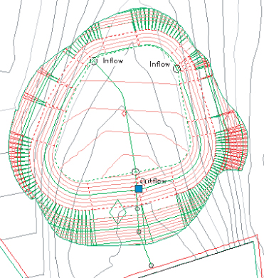
Figure 16.47 Reviewing the grading group volumes

16.47
This tab also allows you to review the criteria and styles being used in the grading group.
20. Click OK to dismiss the Grading Group Properties - Pond Grading dialog.

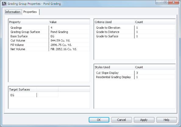
This new surface is listed in Prospector and is based on the gradings created. A change to the gradings would affect the grading group, which would, in turn, affect the surface and these volumes.

When this exercise is complete, you may close the drawing. A saved copy of this drawing is available from the book's web page with the filename CreatingGradingSurfaces_FINISHED.dwg or CreatingGradingSurfaces_METRIC_FINISHED.dwg.

In the last exercise, you'll pull it all together and generate a composite surface from your grading surface and existing surface:

1. Open the CreatingCompositeSurfaces.dwg or CreatingCompositeSurfaces_METRIC.dwg file.
2. Right-click Surfaces in Prospector and select Create Surface.
3. In the Create Surface dialog, enter Composite in the Name text box.
4. Click in the Style field, and then click the ellipsis to display the Select Surface Style dialog.
5. Select the Elevation Banding (2D) option from the drop-down list box, and click OK to dismiss the Select Surface Style dialog.
6. Click OK to dismiss the Create Surface dialog and create the surface in Prospector.
7. In Prospector, expand the Surfaces ⇒ Composite ⇒ Definition branches.
8. Right-click Edits and select Paste Surface.
The Select Surface To Paste dialog appears.
9. Select EG from the list and click OK. Dismiss Panorama if it appears.
10. Right-click Edits again and select Paste Surface one more time.
11. Select Pond Grading and click OK.
12. Right-click the new Composite surface, and select Display Order ⇒ Send To Back.
The drawing should look like Figure 16.48.

Figure 16.48 Completed composite surface

16.48

When this exercise is complete, you may close the drawing. A saved copy of this drawing is available from the book's web page with the filename CreatingGradingSurfaces_FINISHED.dwg or CreatingGradingSurfaces_METRIC_FINISHED.dwg.

By creating a composite surface consisting of pasted-together surfaces, the TIN triangulation cleans up any gaps in the data, making contours that are continuous from the original grade, through the pond, and out the other side. With the grading group still being dynamic and editable, this composite surface reflects a dynamic grading solution that will update with any changes. Using a composite surface such as this as a reference for pipe networks is very useful, since the network may occur under both existing and proposed surfaces.

The Bottom Line

Convert existing linework into feature lines.

Many site features are drawn initially as simple linework for the 2D plan. By converting this linework to feature line information, you avoid a large amount of rework. Additionally, the conversion process offers the ability to drape feature lines along a surface, making further grading use easier.

Master It

Open the MasteringGrading.dwg or MasteringGrading_METRIC.dwg file from the book's web page. Convert the magenta polyline, describing a proposed temporary swale, into a feature line and drape it across the EG surface to set elevations, and set intermediate grade break points.

Model a simple linear grading with a feature line.

Feature lines define linear slope connections. This can be the flow of a drainage channel, the outline of a building pad, or the back of a street curb. These linear relationships can help define grading in a model, or simply allow for better understanding of design intent.

Master It

Edit the curve on the feature line you just created to be 100′ (30 m). Set the grade from the west end of the feature line to the next PI to 4 percent, and the remainder to a constant slope to be determined in the drawing. Draw a temporary profile view to verify the channel is below grade for most of its length.

Model planar site features with grading groups.

Once a feature line defines a linear feature, gradings collected in grading groups model the lateral projections from that line to other points in space. These projections combine to model a site much like a TIN surface, resulting in a dynamic design tool that works in the Civil 3D environment.

Master It

Use the two grading criteria to define the pilot channel, with grading on both sides of the sketched centerline. Define the channel using a Grading to Distance of 5′ (1.5 m) with a slope of 3:1 and connect the channel to the EG surface using a grading with slopes that are 4:1. Generate a surface from the grading group. If prompted, do not weed the feature line.

..................Content has been hidden....................

You can't read the all page of ebook, please click here login for view all page.
Reset