Chapter 5
Parcels
Land development projects often involve the subdivision of large pieces of land into smaller lots. Even if your projects don't directly involve subdivisions, you're often required to show the legal boundaries of your site and the adjoining sites.
AutoCAD® Civil 3D® parcels give you a dynamic way to create, edit, manage, and annotate these legal land divisions. If you edit a parcel segment to make a lot larger, all of the affected labels will update — including areas, bearings, distances, curve information, and table information.
In this chapter, you will learn to:
- Create a boundary parcel from objects
- Create a right-of-way parcel using the right-of-way tool
- Create subdivision lots automatically by layout
- Add multiple-parcel segment labels
Introduction to Sites
In Civil 3D, a site is a collection of parcels, alignments, grading objects, and feature lines that share a common topology. In other words, Civil 3D objects that are in the same site are related to, as well as interact with, one another. The objects that react to one another are called site geometry objects.
The following objects must be placed on a site:
- Feature lines
- Grading groups
- Parcels
Feature lines and grading groups are discussed in depth in Chapter 16, “Grading.” Alignments, discussed in the next chapter, do not need to go on a site.
Think Outside of the Lot
You will want to separate by site any objects you don't want interfering with one another. For example, you may have a set of parcels that represent impervious areas for drainage calculations. In the same location, you may have parcels representing property boundaries. By keeping these items on separate sites, you will be able to keep area information separate.
Dynamic area labels are useful for delineating and analyzing soil boundaries; paving, open space, and wetlands areas; and any other region enclosed with a boundary.
Like all Civil 3D objects, parcels utilize styles. Parcel styles can be used to color-code different parcel types.
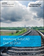
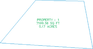
It's important to understand how site geometry objects react to one another. Figure 5.1 shows a typical parcel that might represent a property boundary.
Figure 5.1 A typical property boundary
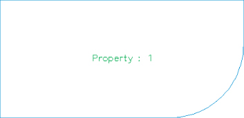
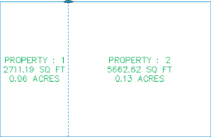
When an alignment is drawn and placed on the same site as the property boundary, the parcel splits into two parcels, as shown in Figure 5.2.
Figure 5.2 An alignment that crosses a parcel divides the parcel in two if the alignment and parcel exist on the same site.
You must plan ahead to create meaningful sites based on interactions between the desired objects. For example, if you want a road centerline, a road right-of-way (ROW) parcel, and the lots in a subdivision to react to one another, they need to be in the same site (see Figure 5.3).
Figure 5.3 Alignments, ROW parcels, open space parcels, and subdivision lots react to one another when drawn on the same site.
The alignment (or road centerline), ROW parcel, and lots all relate to one another. A change in the centerline of the road should prompt a change in the ROW parcel and the subdivision lots.
If you'd like to avoid the interaction between site geometry objects, place them in different sites. Figure 5.4 shows an alignment that has been placed in a different site from the boundary parcel. Notice that the alignment doesn't split the boundary parcel.
Figure 5.4 An alignment that crosses a parcel won't interact with the parcel if they exist on different sites.

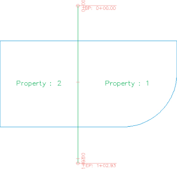
It's important that only objects that are intended to react to each other be placed in the same site. For example, in Figure 5.5 you can see parcels representing both subdivision lots and soil boundaries. Because it wouldn't be meaningful for a soil boundary parcel segment to interrupt the area or react to a subdivision lot parcel, the subdivision lot parcels have been placed in a Subdivision Lots site, and the soil boundaries have been placed in a Soil Boundaries site.
Figure 5.5 Parcels can be used for subdivision lots and soil boundaries as long as they're kept in separate sites.

If you didn't realize the importance of site topology, you might create both your subdivision lot parcels and your soil boundary parcels in the same site and find that your drawing looks similar to Figure 5.6. This figure shows the soil boundary segments dividing and interacting with subdivision lot parcel segments, which doesn't make any sense.
Figure 5.6 Subdivision lots and soil boundaries react inappropriately when placed in the same site.

Another way to avoid site geometry problems is to do site-specific tasks in different drawings and use a combination of external references and data references to share information. For example, you could have an existing base drawing that housed the Soil Boundaries site, XRef'd into a subdivision plat drawing that housed the Subdivision Lots site instead of separating the two drawings onto two different sites.
You should consider keeping your legal site plan in its own drawing. Because of the interactive and dynamic nature of Civil 3D parcels, it might be easy to accidentally grab a parcel segment when you meant to grab a manhole, and unintentionally edit a portion of your plat.
You'll see additional examples and drawing divisions later in this chapter, as well as in Chapter 18, “Advanced Workflows.”
If you decide to have sites in the same drawing, here are some sites you may want to create. These suggestions are meant to be used as a starting point. Use them to help find a combination of sites that works for your projects:
Roads and Lots
This site could contain road centerlines, ROWs, platted subdivision lots, open space, adjoining parcels, utility lots, and other aspects of the final legal site plan.
Grading
Feature lines and grading objects are considered part of site geometry. If you're using these tools, you must make at least one site for them. You may even find it useful to have several grading sites.
Easements
If you'd like to use parcels to manage, analyze, and annotate your easements, you may consider creating a separate site for easements.
Impervious Areas
If you'd like to use parcels to manage, analyze, and annotate paved areas, a separate site will be useful. Drainage areas can be tracked using a separate object called a catchment, so there is no need to create a site for drainage areas. You will learn more about catchments in Chapter 15, “Storm and Sanitary Analysis.”
As you learn new ways to take advantage of alignments, parcels, and grading objects, you may find additional sites that you'd like to create at the beginning of a new project.
Creating a New Site
You can create a new site in Prospector. You'll find the process easier if you brainstorm potentially needed sites at the beginning of your project and create those sites right away — or, better yet, save them as part of your standard Civil 3D template. You can always add or delete sites later in the project.
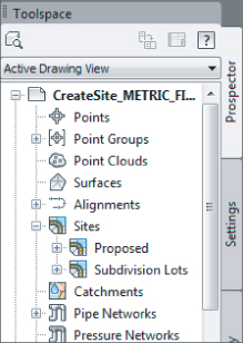
The Sites collection is stored in Prospector, along with the other Civil 3D objects in your drawing.
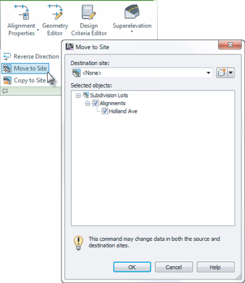
The following exercise will lead you through creating a new site that you can use for creating subdivision lots:
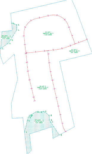
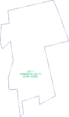
Figure 5.7 The Create Site drawing contains alignments and a boundary parcel.

Figure 5.8 Confirm the settings on the 3D Geometry tab.

Figure 5.9 Your new site is listed in Prospector.
Creating a Boundary Parcel
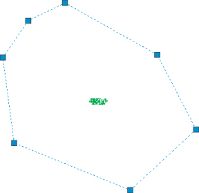
The Create Parcel From Objects tool allows you to create parcels by choosing AutoCAD entities in your drawing or in an XRef'd drawing. In a typical workflow, it's common to encounter a boundary created by AutoCAD entities, such as polylines, lines, and arcs.
When you're using AutoCAD geometry to create parcels, it's important that the geometry be created carefully and meet certain requirements. The AutoCAD geometry must be lines, arcs, polylines, 3D polylines, or polygons. It can't include blocks, ellipses, circles, or other entities. Civil 3D may allow you to pick objects with an elevation other than zero, but you'll find you get better results if you flatten the objects so all objects have an elevation of zero. Sometimes the geometry appears sound when elevation is applied, but you may notice this isn't the case once the objects are flattened. Flattening all objects before creating parcels can help you prevent frustration when creating parcels.
This exercise will teach you how to create a parcel from Civil 3D objects:
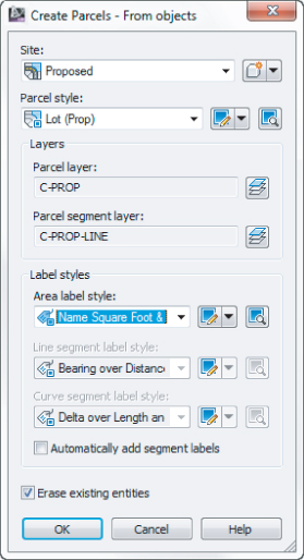
Figure 5.10 Site and Style settings for your new boundary parcel
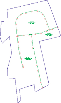
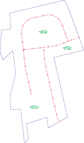
The boundary polyline forms parcel segments that react with the alignments. Area labels are placed at the newly created parcel centroids, as shown in Figure 5.11.
Figure 5.11 The boundary parcel segments, alignments, and area labels
Using Parcel Creation Tools
When you don't have existing lines to work with, the best option is to draw parcel segments using the Parcel Layout tools. Figure 5.12 shows the many commands available to you.
Figure 5.12 Selecting Parcel Creation Tools

Although you may never have thought of things like wetland areas or easements as parcels in the past, you can take advantage of the parcel tools to assist in labeling, stylizing, and analyzing these features for your plans.
This exercise will teach you how to create a parcel representing wetlands using the transparent commands and Draw Tangent-Tangent With No Curves tool from the Parcel Layout Tools toolbox:
![]()
![]()
![]()
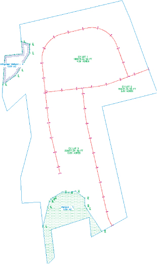
Figure 5.13 The wetlands defined on the site
Your parcels will look like Figure 5.14.
Figure 5.14 The wetlands parcel with the appropriate label styles applied
Creating a Right-of-Way Parcel
The Create ROW tool creates ROW parcels on either side of an alignment based on your specifications. The Create ROW tool can be used only when alignments are placed on the same site as the boundary parcel. The resulting ROW parcel will look similar to Figure 5.15.
Figure 5.15 The resulting parcels after application of the Create ROW tool

Options for the Create ROW tool include:
- Offset distance from alignment
- Fillet or chamfer cleanup at parcel boundaries
- Alignment intersections
Figure 5.16 shows an example of chamfered cleanup at alignment intersections.
Figure 5.16 A ROW with chamfer cleanup at alignment intersections

Once the ROW parcel is created, it's no different from any other parcel. For example, it doesn't maintain a dynamic relationship with the alignment that created it. A change to the alignment will require the ROW parcel to be edited or, more likely, re-created.
This exercise will teach you how to use the Create ROW tool to automatically place a ROW parcel for each alignment on your site:
Figure 5.17 The Create Right Of Way dialog
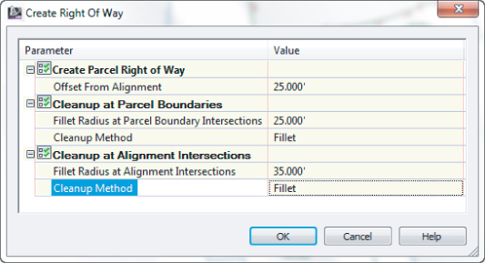
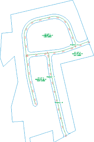
Figure 5.18 The completed ROW parcels
Adding a Cul-de-Sac Parcel
If you look at your drawing, on the lower-left side of your right of way it looks incomplete. You will add a cul-de-sac here. Rather than go through all the mechanics of a cul-de-sac, a block has been created for you and you will insert it and turn it into a parcel. This section also introduces some editing tools.
You will need to have completed the previous exercise before continuing or open the “FINISHED” version of the drawing.
Figure 5.19 Inserting the cul-de-sac block settings
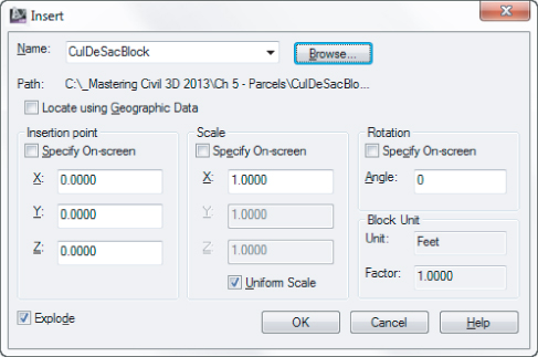
![]()
- Site is set to Subdivision Lots
- Parcel Style is set to Property
- Area Label Style is set to Name Square Foot & Acres (Name Square Meter & HA)
- Erase Existing Entities is checked
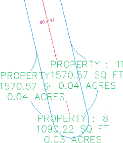
Figure 5.20 The cul-de-sac turned into a parcel
![]()
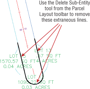
Figure 5.21 Delete these portions.
Your cul-de-sac is complete, as shown on Figure 5.22.
Figure 5.22 The finished cul-de-sac

Creating Subdivision Lot Parcels Using Precise Sizing Tools
The precise sizing tools allow you to create parcels to your exact specifications. You'll find these tools most useful when you have your roadways established and understand your lot-depth requirements. These tools provide automatic, semiautomatic, and freeform ways to control frontage, parcel area, and segment direction.
Attached Parcel Segments
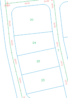
Parcel segments created with the precise sizing tools are called attached segments. Attached parcel segments have a start point that is attached to a frontage segment and an endpoint that is defined by the next parcel segment they encounter. Attached segments can be identified by their distinctive diamond-shaped grip at their start point and no grip at their endpoint (see Figure 5.23).
Figure 5.23 A series of attached parcel segments, with their endpoints at the front lot line
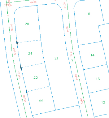
In other words, you establish their start point and their direction, but they seek another parcel segment to establish their endpoint. Figure 5.23 shows a series of attached parcel segments. You can tell the difference between their start and endpoints because the start points have the diamond-shaped grips.
You can drag the diamond-shaped grip along the frontage to a new location, and the parcel segment will maintain its angle from the frontage. If the rear lot line is moved or erased, the attached parcel segments find a new endpoint (see Figure 5.24) at the next available parcel segment.
Figure 5.24 The endpoints of attached parcel segments extend to the next available parcel segment if the initial parcel segment is erased.
Precise Sizing Settings
The precise sizing tools consist of the Slide Angle, Slide Direction, and Swing Line tools (see Figure 5.25).
Figure 5.25 Helpful parcel segment creation tools on the Parcel Layout Tools toolbar

The Parcel Layout Tools toolbar can be expanded so that you can establish settings for each of the precise sizing tools (see Figure 5.26). Each of these settings is discussed in detail in the following sections.
Figure 5.26 Automated sizing options on the expanded Parcel Layout Tools toolbar
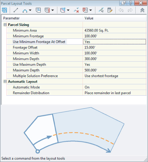
New Parcel Sizing
![]()
When you create new parcels, the tools respect your default area and minimum frontage (measured from either a ROW or a building setback line). The program always uses these numbers as a minimum; it bases the actual lot size on a combination of the geometry constraints (lot depth, frontage curves, and so on) and the additional settings that follow. Keep in mind that the numbers you establish under the New Parcel Sizing option must make geometric sense. For example, if you'd like a series of 7,500 square foot (700 square meter) lots that have 100′ (30 m) of frontage, you must make sure that your rear parcel segment allows for at least 75′ (23 m) of depth; otherwise, you may wind up with much larger frontage values than you desire or a situation where the software can't return a meaningful result.
Automatic Layout
Automatic Layout has two parameters when the list is expanded: Automatic Mode and Remainder Distribution. The Automatic Mode parameter can have the following values:
On
Automatically follows your settings and puts in all the parcels, without prompting you to confirm each one.
Off
Allows you to confirm each parcel as it's created. In other words, this option provides you with a way to semiautomatically create parcels.
The Remainder Distribution parameter tells Civil 3D how you'd like “extra” land handled. This parameter has the following options:
Create Parcel From Remainder
Makes a last parcel with the leftovers once the tool has made as many parcels as it can to your specifications on the basis of the settings in this dialog. This parcel is usually smaller than the other parcels.
Place Remainder In Last Parcel
Adds the leftover area to the last parcel once the tool has made as many parcels as it can to your specifications on the basis of the settings in this dialog.
Redistribute Remainder
Takes the leftover area and pushes it back through the default-sized parcels once the tool has made as many parcels as it can to your specifications on the basis of the settings in this dialog. The resulting lots aren't always evenly sized because of differences in geometry around curves and other variables, but the leftover area is absorbed.
There aren't any rules per se in a typical subdivision workflow. Typically the goal is to create as many parcels as possible within the limits of available land. To that end, you'll use a combination of AutoCAD tools and Civil 3D tools to divide and conquer the particular tract of land with which you are working.
Slide Line – Create Tool
The Slide Line – Create tool creates an attached parcel segment based on an angle from frontage. You may find this tool most useful when your jurisdiction requires a uniform lot-line angle from the right of way.
This exercise will lead you through using the Slide Line – Create tool to create a series of subdivision lots:
![]()
- Minimum Area: 7500.00 sq. ft. (700 m2)
- Minimum Frontage: 75.000′ (25 m)
- Use Minimum Frontage At Offset: Yes
- Frontage Offset: 25.000′ (10 m)
- Minimum Width: 75.000′ (25 m)
- Minimum Depth: 50.000′ (15 m)
- Use Maximum Depth: No
- Maximum Depth: (leave default value as this will not be used)
- Multiple Solution Preference: Use shortest frontage
- Automatic Mode: On
- Remainder Distribution: Redistribute remainder
![]()
Figure 5.27 Pick the point of curvature along the ROW parcel segment.

Figure 5.28 Allow the parcel-creation jig to follow the parcel segment, and then pick the point of curvature along the ROW parcel segment.

Figure 5.29 A preview of the results of the automatic parcel layout

Figure 5.30 The automatically created lots

The parcels at the north end just don't look right. We'll address that in the next section of this chapter.

Swing Line – Create Tool
The Swing Line – Create tool creates a “backward” attached parcel segment where the diamond-shaped grip appears not at the frontage but at a different location that you specify. The tool respects your minimum frontage, and it adjusts the frontage so it is larger, if necessary, in order to respect your default area. The Swing Line – Create tool is semiautomatic because it requires your input of the swing point location.
You may find this tool most useful around a cul-de-sac or in odd-shaped corners where you must hold frontage but have a lot of flexibility in the rear of the lot.
Using the Free Form Create Tool
A site plan is more than just single-family lots. Areas are usually dedicated for open space, stormwater-management facilities, parks, and public utility lots. The Free Form Create tool can be useful when you're creating these types of parcels. This tool, like the precise sizing tools, creates an attached parcel segment with the special diamond-shaped grips.
In the following exercise, you'll use the Free Form Create tool to create a new parcel:
Figure 5.31 Delete the highlighted parcel line.

![]()
Figure 5.32 Use the Free Form Create tool to select an attachment point.
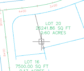
Figure 5.33 Attach the parcel segment to the marker point provided.
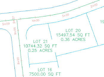
Figure 5.34 Sliding an attached parcel segment

Notice that when you place the parcel segment at a new location, the segment endpoint snaps back to the rear parcel segment. This is typical behavior for an attached parcel segment.
Editing Parcels by Deleting Parcel Segments
One of the most powerful aspects of Civil 3D parcels is the ability to perform many iterations of a site plan design. Typically, this design process involves creating a series of parcels and then deleting them to make room for iteration with different parameters, or deleting certain segments to make room for easements, public utility lots, and more.
You can delete parcel segments using the AutoCAD Erase tool as shown in the previous exercise, or the Delete Sub-Entity tool on the Parcel Layout Tools toolbar.
It's important to understand the difference between these two methods. The AutoCAD Erase tool behaves as follows:
- If the parcel segment was originally created from a polyline (or similar parcel layout tools, such as the Tangent-Tangent With No Curves tool), the AutoCAD Erase tool erases the entire segment (see Figure 5.35).
Figure 5.35 The segments indicated by the blue grips will be erased after using the AutoCAD Erase tool.
- If the parcel segment was originally created from a line or arc (or similar parcel layout tools, such as the precise sizing tools), then AutoCAD Erase erases the entire length of the original line or arc (see Figure 5.36).
Figure 5.36 The AutoCAD Erase tool will erase the entire segment indicated by the blue grips.

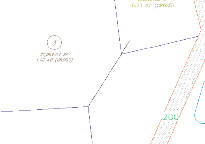
The Delete Sub-Entity tool acts more like the AutoCAD Trim tool. The Delete Sub-Entity tool only erases the parcel segments between parcel vertices. For example, if Lot 26, as shown in Figure 5.37, must be absorbed into Lot 3 to create a public utility easement, you'd want to only erase the segment at the rear of Lot 26 and not the entire segment shown previously in Figure 5.36.
Figure 5.37 Use the Delete Sub-Entity tool to erase the rear parcel segment for Lot 26.
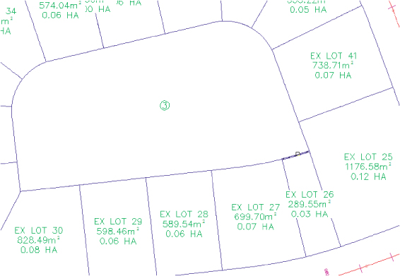
As an alternate to launching from the Home tab ⇒ Create Ground Data panel ⇒ Parcel ⇒ Parcel Creation tools, you can access the Parcel Creation tools by selecting a lot label. From the Parcel contextual tab ⇒ Modify panel, select Parcel Layout Tools. Selecting the Delete Sub-Entity tool allows you to pick only the small rear parcel segment for Lot 26. Figure 5.38 shows the result of this deletion.
Figure 5.38 The rear lot line for Lot 26 was erased using the Delete Sub-Entity tool, thus creating a larger Lot 3.

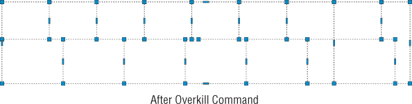
The following exercise will lead you through deleting a series of parcel segments using both the AutoCAD Erase tool and the Delete Sub-Entity tool:
Figure 5.39 The parcel lines to be deleted
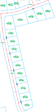
Figure 5.40 The re-created lots
![]()
The resulting parcel is shown in Figure 5.41.
Figure 5.41 The parcel after erasing the rear lot line

Best Practices for Parcel Creation
Now that you have an understanding of how objects in a site interact and you've had some practice creating and editing parcels in a variety of ways, we'll take a deeper look at how parcels must be constructed to achieve topology stability, predictable labeling, and desired parcel interaction.
Forming Parcels from Segments
Earlier in this chapter, you saw that parcels are created only when parcel segments form a closed area (see Figure 5.42).
Figure 5.42 A parcel is created when parcel segments form a closed area.
Parcels must always close. Whether you draw AutoCAD lines and use the Create Parcel From Objects menu command or use the parcel segment creation tools, a parcel won't form until there is an enclosed polygon. Figure 5.43 shows four parcel segments that don't close; therefore, no parcel has been formed.
Figure 5.43 No parcel will be formed if parcel segments don't completely enclose an area.

There are times in surveying and engineering when parcels of land don't necessarily close when created from legal descriptions. In this case, you must work with your surveyor to perform an adjustment or find some other solution to create a closed polygon.
You also saw that even though parcels can't be erased, if you erase the appropriate parcel segments, the area contained within a parcel is assimilated into neighboring parcels.
Parcels Reacting to Site Objects
Parcels require only one parcel segment to divide them from their neighbor (see Figure 5.44). This behavior eliminates the need for duplicate segments between parcels, and duplicate segments must be avoided.
Figure 5.44 Two parcels, with one parcel segment between them

As you saw in the section on site interaction, parcels understand their relationships to one another. When you create a single parcel segment between two subdivision lots, you have the ability to move one line and affect two parcels. Figure 5.45 shows the moved parcel segment from Figure 5.44 once the parcel segment between them has been shifted to the left. Note that both areas change in response.
Figure 5.45 Moving one parcel segment affects the area of two parcels.
A mistake that many people new to Civil 3D make is to create parcels from closed polylines, which results in a duplicate segment between parcels. Figure 5.46 shows two parcels created from two closed polylines. These two parcels may appear identical to the two seen in the previous example, because they were both created from a closed polyline rectangle; however, the segment between them is actually two segments.
Figure 5.46 Adjacent parcels created from closed polylines create overlapping or duplicate segments.

The duplicate segment becomes apparent when you attempt to grip-edit the parcel segments. Moving one vertex from the common lot line, as seen in Figure 5.47, reveals the second segment. Also note that a sliver parcel is formed. Duplicate site geometry objects and sliver parcels make it difficult for Civil 3D to solve the site topology and can cause unexpected parcel behavior.
Figure 5.47 Duplicate segments become apparent when they're grip-edited and a sliver parcel is formed.

Creating a subdivision plat of parcels this way almost guarantees that your labeling won't perform properly and could lead to inaccurate data.
Parcels form to fill the space contained by the original outer boundary. You should always begin a parcel-division project with an outer boundary of some sort (see Figure 5.48).
Figure 5.48 An outer boundary parcel
You can then add road centerline alignments to the site, which divides the outer boundary, as shown in Figure 5.49.
Figure 5.49 Alignments added to the same site as the boundary parcel divide the boundary parcel.
It's important to note that the boundary parcel no longer exists intact. As you subdivide this site, Parcel 1 is continually reallocated with every division. As road ROW and subdivision lots are formed from parcel segments, more parcels are created. Every bit of space that was contained in the original outer boundary is accounted for in the mesh of newly formed parcels (see Figure 5.50).
Figure 5.50 The total area of parcels contained within the original boundary sums to equal the original boundary area.

From now on, you'll consider ROW, wetlands, parkland, and open space areas as parcels, even if you didn't before. You can make custom label styles to annotate these parcels however you like, including a “no show” or none label.
![]()


Constructing Parcel Segments with the Appropriate Vertices
Parcel segments should have natural vertices only where necessary and split-created vertices at all other intersections. A natural vertex, or point of intersection (PI), can be identified by picking a line, polyline, or parcel segment and noting the location of the grips (see Figure 5.51).
Figure 5.51 Natural vertices on a parcel segment

A split-created vertex occurs when two parcel segments touch or cross each other. Note that in Figure 5.52, the parcel segment doesn't show a grip even where each individual lot line touches the ROW parcel.
Figure 5.52 Split-created vertices on a parcel segment
It's desirable to have as few natural vertices as possible. In the example shown in Figure 5.52, the ROW frontage line can be expressed as a single bearing and length from the end of the arc through the beginning of the next arc, as opposed to having several smaller line segments.
If the foundation geometry was drawn with a natural vertex at each lot line intersection, the resulting parcel segment won't label properly and may cause complications with editing and other functions. This subject will be discussed in more detail in the section “Labeling Spanning Segments,” later in this chapter.
Parcel segments must not overhang. Spanning labels are designed to overlook the location of intersection-formed (or T-shaped) split-created vertices. However, these labels won't span a crossing-formed (X- or + [plus]-shaped) split-created vertex. Even a very small parcel segment overhang will prevent a spanning label from working and may even affect the area computation for adjacent parcels. The overhanging segment in Figure 5.53 would prevent a label from returning the full spanning length of the ROW segment it crosses.
Figure 5.53 Overhanging segment
Labeling Parcel Areas
A parcel area label is placed at the parcel centroid by default, and it refers to the parcel in its entirety. When asked to pick a parcel, you pick the area label. An area label doesn't necessarily have to include the actual area of the parcel.
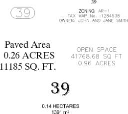
Area labels can be customized to suit your fancy. Figure 5.54 shows a variety of customized area labels.
Figure 5.54 Sample area labels
Area labels often include the parcel name or number. After selecting a parcel, on the Parcel contextual tab ⇒ Modify panel choose Renumber/Rename.
The following exercise will teach you how to renumber a series of parcels:
![]()
Note that your parcels have been renumbered from 1 through 15. Repeat the exercise with other parcels in the drawing for additional practice if desired.
The next exercise will lead you through one method of changing an area label using the Edit Parcel Properties dialog:
![]()
Figure 5.55 The Edit Parcel Properties dialog

![]()
The 15 parcels now have parcel area labels that call out numbers only. Note that you could also use this interface to add a second area label to certain parcels if required.
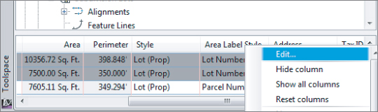
This section's final exercise will show you how to use Prospector to change a group of parcel area labels at the same time:
Figure 5.56 Right-click the Area Label Style column header and select Edit.
![]()

Labeling Parcel Segments
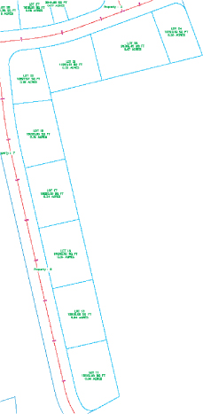
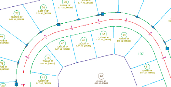
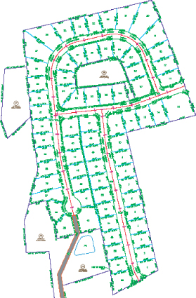
Although parcels are used for much more than just subdivision lots, most parcels you create will probably be used for concept plans, record plats, and other legal subdivision plans. These plans, such as the one shown in Figure 5.57, almost always require segment labels for bearing, distance, direction, crow's feet, and more.
Figure 5.57 A fully labeled site plan
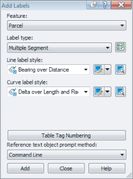
Labeling Multiple-Parcel Segments
The following exercise will teach you how to add labels to multiple-parcel segments:
Figure 5.58 The Add Labels dialog
The following exercise will show you how to edit and delete parcel segment labels:
Figure 5.59 A diamond-shaped grip appears when the label has been picked.
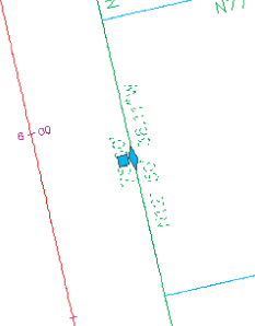
Figure 5.60 The Parcel Segment Label contextual tab

Labeling Spanning Segments
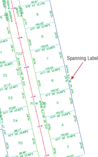
Spanning labels are used where you need a label that spans the overall length of an outside segment, such as the example in Figure 5.61.
Figure 5.61 A spanning label
Spanning labels require that you use the appropriate vertices, as discussed in detail in the earlier section “Constructing Parcel Segments with the Appropriate Vertices.” Spanning labels have the following requirements:
- Spanning labels can only span across split-created vertices. Natural vertices will interrupt a spanning length.
- Spanning label styles must be composed to span the outside segment.
- Spanning label styles must be composed to attach the desired spanning components (such as length and direction arrow) on the outside segment (as shown previously in Figure 5.61), with perhaps a small offset.
Once you've confirmed that your geometry is sound and your label is properly composed, you're set to span. The following exercise will teach you how to add spanning labels to single-parcel segments:
Adding Curve Tags to Prepare for Table Creation
To keep plans tidy, it is common to show labels that reference a table for curves and lines. Civil 3D parcels provide tools for creating dynamic line and curve tables. You can keep lines and curves together or create separate tables for each.
Parcel segments must be labeled before they can be used to create a table. They can be labeled with any type of label, but you'll likely find it to be best practice to create a tag-only style for segments that will be placed in a table.
The following exercise will show you how to replace curve labels with tag-only labels, and then renumber the tags:
Now that each curve label has been replaced with a tag, it's desirable to have the tag numbers be sequential. The following exercise will show you how to renumber tags:
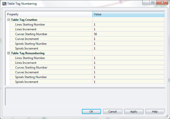
Figure 5.62 Curve tags on Parcel 11


Figure 5.63 The Table Tag Numbering dialog
Creating a Table for Parcel Segments
The following exercise demonstrates how to create a table from curve tags:
![]()
Figure 5.64 The Table Creation dialog
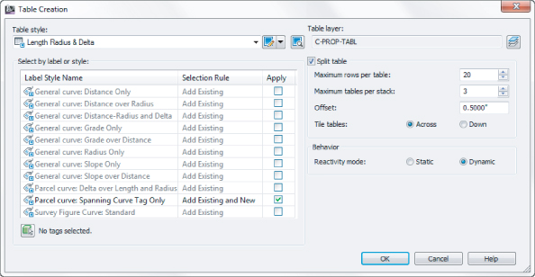
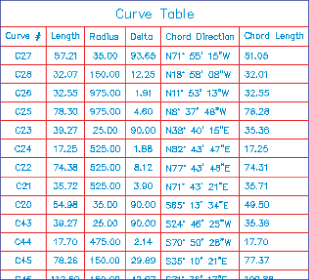
Figure 5.65 A curve table
The Bottom Line
Create a boundary parcel from objects.
The first step to any parceling project is to create an outer boundary for the site.
Master It
Open the MasteringParcels.dwg (MasteringParcels_METRIC.dwg) file, which you can download from www.sybex.com/go/masteringcivil3d2013. Convert the line segments in the drawing to a parcel.
Create a right-of-way parcel using the right-of-way tool.
For many projects, the ROW parcel serves as frontage for subdivision parcels. For straightforward sites, the automatic Create ROW tool provides a quick way to create this parcel. A cul-de-sac serves as a terminal point for a cluster of parcels.
Master It
Continue working in the Mastering Parcels.dwg (MasteringParcels_METRIC.dwg) file. Create a ROW parcel that is offset by 25′ (10 m) on either side of the road centerline with 25′ (10 m) fillets at the parcel boundary and alignment ends. Then add the circles representing the cul-de-sac as a parcel.
Create subdivision lots automatically by layout.
The biggest challenge when creating a subdivision plan is optimizing the number of lots. The precise sizing parcel tools provide a means to automate this process.
Master It
Continue working in the Mastering Parcels.dwg (MasteringParcels_METRIC.dwg) file. Create a series of lots with a minimum of 8,000 sq. ft. (700 m2) and 75′ (20 m) frontage. Set the Use Minimum Offset option to No. Leave all other options at their defaults.
Add multiple-parcel segment labels.
Every subdivision plat must be appropriately labeled. You can quickly label parcels with their bearings, distances, direction, and more using the segment labeling tools.
Master It
Continue working in the MasteringParcels.dwg (MasteringParcels_METRIC.dwg) file. Place Bearing Over Distance labels on every parcel line segment and Delta Over Length And Radius labels on every parcel curve segment using the Multiple Segment Labeling tool.