"The cost-benefit of properly setting up a shoot with an evenly lit greenscreen can be poor when compared to having the compositing team fix the shot."

Alpha channels, and their associated matte information, are cornerstones of compositing. Alpha allows the combination of two or more images, whether the images are part of a layer within After Effects or a node output within Nuke. Although 3D programs generate alpha as part of the rendering process, motion picture and video footage does not contain alpha information. As such, it's necessary to create alpha values. One of the most common techniques for creating alpha is to "key out" blue or green from bluescreen or greenscreen footage. Both After Effects and Nuke offer tools designed specifically for this process. The tutorials at the end of this chapter will give you the opportunity to use these tools by removing a greenscreen from a digital video shoot. In addition, you'll have a chance to revisit the tutorials from Chapter 2 in order to refine alpha edge quality and the overall color balance of the composite.

Alpha is a channel of a digital image that is designed to store matte information. In traditional filmmaking, a matte is a device used to control the exposure of film when two or more elements are optically combined. In the digital realm, the matte establishes pixel transparency and takes the form of a grayscale image stored in the alpha channel. When alpha is examined in a compositing program, a pixel value of 1 (white) represents 100 percent opaqueness and a value of 0 (black) represents 100 percent transparency (see Figure 3.1). (The word mask is often used to describe a matte; for more information, see Chapter 7, "Masking, Rotoscoping, and Motion Tracking.")
Various image formats support alpha by making it an integrated fourth channel (written as RGBA). Those formats include Maya IFF, OpenEXR, RLA, SGI, Targa, and TIFF. 3D programs, such as Autodesk's Maya and 3ds Max, give the user the option of rendering out the alpha channel. It's also possible to create an alpha channel from scratch in digital imaging programs such as Photoshop. Digitized motion picture footage and digital video, however, do not provide an alpha channel; as such, an alpha channel must be generated or otherwise "pulled" in the compositing program through various matte tools.
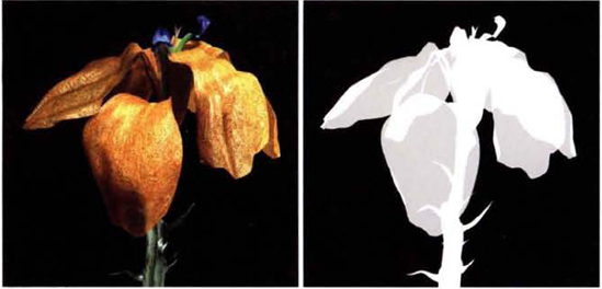
Figure 3.1. (Left) CG flower (Right) Corresponding alpha channel. Since the petals have a slight transparency, the alpha values are gray in those areas. The render is included as flower.tga in the Footage folder on the DVD.
Premultiplication, on the other hand, is an optional alpha process. When a 3D program, such as Maya or 3ds Max, renders an image with an alpha channel, the RGB channel values are multiplied by the alpha channel values. For example, if the normalized RGB values of a pixel are 1.0, 0.5, 0.7 and the corresponding alpha value is 0.5, then the premultiplied RGB pixel values become 0.5, 0.25, 0.35. Premultiplied pixel values are mathematically more efficient during the compositing process because the alpha values have been preinterpreted. One disadvantage, however, is that the premultiplied color values are less accurate than unpremultiplied values, which can affect the accuracy of color filters, color grading, and greenscreen removal (see Chapter 8, "DI, Color Grading, Noise, and Grain," for more information).
When an image file is imported into a compositing program, it must be interpreted as premultiplied (matted with color) or straight (unmatted). The process can be described with this simplified scenario:
A 3D program renders a surface with anti-aliasing. An edge pixel is assigned an alpha value of 0.5. The RGB values of the pixel are determined to be 1, 1, 1. However, because premultiplication is applied, the RGB values are multiplied by the alpha value and the final assigned RGB values are 0.5, 0.5, 0.5.
The resulting render is brought into a compositing program. The program interprets the render as premultiplied. If the render is composited over the top of a red layer and a Normal blending mode is used, the overlapping pixel value becomes 1, 0.5, 0.5 (light red), which you would expect when placing semitransparent white over red (see Figure 3.2). (The mathematical formula for the Normal blending mode is described in the next section.)
If the alpha is incorrectly interpreted as straight, each color channel is multiplied by the alpha channel at the point that the render is blended with the red background. Therefore, the edge pixel is assigned an incorrect color value of 0.75, 0.25, 0.25. This forms a gray line around the surface that becomes exaggerated when motion blur is present and there are a greater number of semitransparent pixels (see Figure 3.2).

Figure 3.2. (Top Left) A CG surface with motion blur, composited over a red background, has its alpha interpreted as straight. This produces a gray line along the edge. (Top Right) Same surface with its alpha interpreted as premultiplied. (Bottom Left) A CG jar, composited over a white background, has its alpha interpreted as straight. This produces a gray line around the edge. (Center) Same jar with alpha interpreted as premultiplied. The renders are included as blur.tga and jar.tga in the Footage folder on the DVD.
Alpha channels, and their corresponding mattes, are a critical part of compositing. Yet there are many methods by which the matte is used when combining or layering images. These combinations are commonly known as blending modes. (Nuke refers to them as merge operations.) As a compositor, it's important to understand the various blending modes and have a strong concept of the math that lies behind them.
Keep in mind that alpha channels are optional. It's possible, and quite common, to apply blending modes to two images that do not carry alpha channels. In such a case, the blending happens to the full image, whereas a matte limits the effect to whatever is defined as opaque or semi-opaque.
Common blending modes include Normal (Over), Stencil, Add (Plus), Screen, Multiply, Lighten (Max), and Darken (Min). There are numerous additional variations of blending modes. In fact, After Effects and Nuke each offer over 30.
The most common blending mode is Normal (Adobe) or Over (Nuke). In a layer-based compositing program, this means that the top layer (A) obscures the lower layer (B), except where the top layer is transparent. In a node-based compositing program, this means that input A obscures input B. In traditional compositing math, the A and B relationship is often laid out as a formula. The small a or b signifies the alpha channel value of A or B. The C represents the resulting pixel value:
A + (B × (1 - a)) = C
This formula assumes that the alpha values have been premultiplied. Otherwise, we can write the formula like this:
(A × a) + ((B × b) × (1 - a)) = C
This formula processes one color channel at a time. For example, the red channel pixel values are dealt with first. With this formula, the alpha channel of A, which is a, is inverted and multiplied by the red channel pixel value of B. Hence, if a has a value of 1.0, the contribution of the corresponding B pixel value becomes 0. On the other hand, if a has a value of 0.5, the A and B red channel pixel values are averaged. For example, if A has a value of 1.0 and B has a value of 0.2, the following occurs:
(1.0 × 0.5) + ((0.2 × 1.0) (1 − 0.5)) = 0.6
The Normal/Over method can also be represented visually (see Figure 3.3).
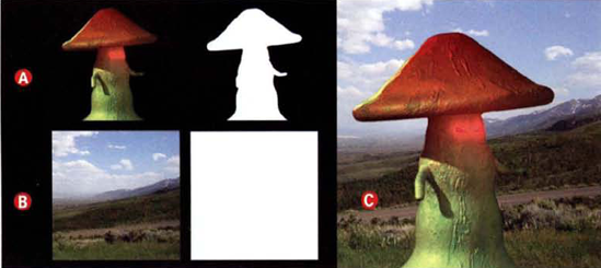
Figure 3.3. (Top Left) Layer A mushroom element over black (Top Center) Layer A alpha channel (Bottom Left) Layer B mountain plate (Bottom Center) Layer B alpha channel (Right) Resulting composite with Normal (Over) blending mode. The images are included as mushroom.##.tif and mountain.tif in the Footage folder on the DVD.
In contrast, the Stencil blending mode uses a section of the Normal (Over) formula:
B × (1 - a) = C
For example, if a is 0.75, then B is multiplied by 0.25. If B started with a value of 1.0, its end value is 0.25. Thus, B appears only where a is less than 1.0. In other words, a hole in the shape of a is cut into B (see Figure 3.4).

Whereas Nuke offers a Stencil operation for its Merge node, After Effects provides two variations. The Silhouette Alpha blending mode cuts a hole in the shape of a into B. The Stencil Alpha blending mode does the opposite by cutting B out into the shape of a.
Add (Adobe) and Plus (Nuke) offer a simple formula:
A + B = C
This allows the final pixel to exceed the normalized 1.0 threshold and carry superwhite values—for example, 0.7 + 0.6 = 1.3. This often results in a washed-out, overexposed composite. To avoid the superwhite values, the Screen blending mode is offered. Screen uses the following math:
(A + B) - (A × B) = C
(0.7 + 0.6) - (0.7 × 0.6) = 0.88
1.3 − 0.42 = 0.88
Screen is useful for blending bright elements against a darker background. Screen does not employ alpha values; as such, A does not have to carry an alpha channel. Screen is suited for blending smoke, fire, or flares into a background plate (see Figure 3.5). For an additional example of the Screen blending mode, see the next section.

Multiply fulfills its namesake with the formula AB, or A × B. Multiply uses a conditional that tests for negative numbers and converts them into zeroes. This prevents C from becoming a negative value. Multiply is useful for compositing dark elements against lighter backgrounds without allowing the element to become 100 percent opaque. For example, you can use Multiply to blend a stormy sky into a clear one (see Figure 3.6).

Lighten (Adobe) and Max (Nuke) simply use the highest value of two corresponding pixels found in A and B. Darken (Adobe) and Min (Nuke) use the lowest value. The modes can be written as max(A, B) and min(A, B). Lighten is useful for adding bright elements to dark backgrounds. Although Lighten can produce results similar to the Add (Plus) blending mode, it is not subject to clipping. Darken, on the other hand, is useful for blending dark elements into light backgrounds. For instance, in Figure 3.7, the top layer is a CG spaceship render; its blending mode is set to Darken. The middle layer contains a CG render of smoke; its blending mode is set to Screen, allowing the smoke to pick up intensity and the illusion of a glow. The lowest layer holds a background plate of the sky.
When A and B operations are discussed, only two layers, or two inputs, are considered at one time. Hence, the spaceship is multiplied over the net result of the layers below it. Since Nuke is node based, it takes two Merge nodes to create a similar composite. The first Merge node, set to Screen, combines the smoke and the sky. The second Merge node, set to Multiply, combines the spaceship with the output of the first Merge node.

Chroma keying forms a major portion of compositing work for feature visual effects, episodic television, and commercial production work. Compositing packages attempt to automate the process by supplying built-in tools and support for production-strength plug-ins. The automation is rarely perfect, however. Thus it's important to understand what technical steps the keying requires and different approaches that may be available.
Aside from referring to a particular color of backdrop, bluescreen and greenscreen are contemporary names for the chroma key process. All three terms trace their roots to traveling mattes. Traveling mattes were developed in the 1930s by RKO Pictures and fellow studios as a way to combine, with an optical process, foreground action and background images that were otherwise impossible to shoot together. (The mattes were referred to as "traveling" because each frame of the matte changed along with the foreground action.) Motion picture film stock, due to its physical nature, is more sensitive to blue wavelengths; hence, when shooting the foreground action for a traveling matte, cinematographers placed a blue backdrop behind the actors. Blue is also a complimentary color to (Caucasian) human skin tone, which makes keying (the pulling of mattes) somewhat easier. Over the decades that followed, other key colors were utilized, such as sulfur yellow, red, magenta, and green. Greenscreen increased in popularity in the late 1970s due to the growth of video. With analog YUV or digital Y'CbCr video color space, green is indirectly carried by the Y or Y' channel, which means there is generally more data set aside for it than the blue or red channels. (Green is derived by subtracting the blue and red channel values from the luminance or luma channel.)
Chroma key paints and fabrics, on the other hand, refer to specifically formulated materials that produce blues and greens that are optimal for videography and cinematography. The greenscreens shot for this book, for instance, are derived from foam-backed chroma key fabric.
The first step to using a bluescreen or greenscreen plate is to key out the unwanted blue or green using a keyer. Keying out, which is also referred to as keying, removes the unwanted color so that an alpha matte is created for the desired foreground elements. (A plate is a particular piece of footage from a particular camera setup or shot destined for compositing or other visual effects work.) There are several standard approaches to keying that make use of luma, color, and difference mathematics. After the shot is keyed, there are additional techniques that will improve the quality of the matte. These include spill suppression and matte erosion/expansion.
Luma Key One of the simplest approaches to keying a plate is to use the luminance information found in the frames. This is achieved by converting the frames to grayscale and adjusting the values to create a high-contrast (hicon) version that contains mostly 0 blacks and 1.0 whites. The adjustment can be made to all three color channels or to a single color channel where a high degree of contrast between the foreground and background already exists (see Figure 3.8). The RGB values are then fed to the alpha channel of an unmolested version of the plate. Since luma keys ignore color information, they are prone to failure when you're working with plates with little luminance variation. Nevertheless, luma keys are not dependent on bluescreen or greenscreen and can be created from a wide variety of footage that contains sufficient contrast. In fact, generating a matte in such a manner is often referred to as pulling a matte.(Note that the term luma key is shorthand for luminance key and is not directly related to the luma channel of Y'CbCr video.)
Color Key The most logical approach to keying a chroma key plate is to take advantage of a key color. To do so, the frames must be converted from RGB to HSV or HSB color space. By dividing the color range into hue, saturation, and value (or brightness), the keyer is able to identify pixels for keying by examining saturation values. One disadvantage of color keyers is their tendency to produce hard matte edges. However, they can target any color and are not limited to green or blue.
Difference Matte A difference matte necessitates two plates: one with the foreground action against the background (a target plate) and one with only the background (a difference plate). Corresponding pixels of the two plates are compared. Pixels that show significant variation are assigned opaque pixel values in the resulting alpha matte. In anticipation of the difference matte, the camera producing the plates must be locked down; in addition, any significant change in lighting will affect the difference matte's success.
Color Difference Matte A more sophisticated method of keying uses a color difference matte, which determines the difference in values between the RGB channels within a pixel. For example, if a pixel has a value of 0.2, 0.8, 0.2, then it's recognized to be heavily biased toward green. If the plate includes a greenscreen, then the pixel is targeted for transparency because its green channel is significantly different from the red and blue channels. A foreground pixel, on the other hand, may have a value of 0.7, 0.5, 0.6. Because the difference between the green channel and the red and blue channels is relatively minor, the pixel is targeted for opaqueness. Color difference mattes offer the advantage of soft matte edges, where the transition from transparent to opaque pixels can be fairly gradual.
Despill Due to the nature of bluescreen and greenscreen shoots, there is often blue and green that "spills" onto the foreground subject (see Figure 3.11). This is particularly evident when the foreground is physically close to the background screen or the lighting on the foreground is not designed to neutralize any blue or green wavelengths that are reflected from the background. Despill operations target pixels that are heavily saturated by the key color and perform an adjustment. The algorithms controlling despill operations vary. One method clips the values of the offending channel, such as green, to the values of another channel, such as red. A second method generates an internal spill map, which records areas of spill that can be used to subtract the spill color from the image.
Matte Erosion and Expansion It's common for a matte created through keying to suffer from a loose fit. That is, the matte extends past the edge of the foreground object to reveal an inappropriate white or colored line. Conversely, the matte may be too "tight" and therefore erode into the object. Hence, a means by which you can expand or contract the alpha matte is often necessary. In general, erosion and expansion tools, often called chokers, operate by manipulating the alpha channels color curve. The curves are scaled so that the gray, semitransparent values are pushed toward white for a greater degree of opaqueness or pushed toward black for a greater degree of transparency.
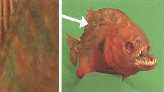
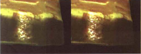
Figure 3.9. Taxidermied fish shot against greenscreen. The close-up on the left shows the high degree of green spill.
After Effects and Nuke offer a wide range of keying effects and nodes that utilize the techniques discussed in this section. Their functionality is detailed in the section "Working with Alpha" later in this chapter.

Here are a few steps to keep in mind when keying:
Multiple Keyers When keying, you are not limited to using a single keyer. Instead, feel free to apply a different keyer with a different setting to various regions of the image. You can define particular regions by drawing masks. You can then combine the alpha channels of the various regions to create a final matte (see Chapter 7, "Masking, Rotoscoping, and Motion Tracking," for examples).
Alpha Color Correction You can apply various color-correction effects and nodes to help improve the quality of a resulting alpha channel. In After Effects, you can use a filter that can target the alpha channel without influencing the RGB channels. The Curves and Levels effects do so by offering a Channel menu. In Nuke, you can change the Channels menu in any node's properties panel to Alpha.
Timeline Test When working with footage, test the keyer settings at different frames. If necessary, animate the keyer settings over time. If the foreground objects are changing too dramatically, consider applying multiple keyers to individual portions of the timeline. For example, apply keyer 1 from frames 1 to 100 and keyer 2 from frames 101 to 150.
Rotoscoping if you're having difficultly keying a piece of footage or the key is producing unclean matte edges, consider rotoscoping. Despite the advances in keyer technology, rotoscoping remains a common practice at animation studios and visual effects houses. In addition, rotoscoping is generally required when there is no greenscreen or bluescreen, the screens are not large enough to cover the entire background, or reflective surfaces are involved. (Rotoscoping is discussed in Chapter 7.)
Lab and YUV Color Consider converting the footage to L*a*b* or YUV color space. L*a*b* (often written as Lab) separates luminance information from chrominance information. The L* channel handles luminance, or "lightness." The a* channel controls the green-red color balance. The b* channel controls the blue-yellow color balance. In the realm of computer graphics, YUV generally refers to digital file formats encoded in Y'CbCr color space. YUV divides the luminance and chrominance information in a similar manner. U (or Cb) encodes the blue chroma component. V (or Cr) encodes the red chroma component. The green chroma component is indirectly carried by the Y channel.
Since the noise found in film and digital video footage is more strongly represented in chrominance channels, it can pay to apply noise suppression techniques (such as subtle blurs) to the a*/U/Cb or b*/V/Cr channels only. Ultimately, the presence of noise interferes with the proper operation of chroma keyer effects and nodes. Conversely, many compositors prefer to sharpen their images in L*a*b* or YUV space. By applying a sharpen filter to the L*/Y channel, you bypass the greater degree of noise inherent in the a*/U/Cb and b*/V/Cr channels. This results in fewer sharpening artifacts, including white edge "halos."
After Effects supports L*a*b* and YUV through the Color Range effect, which is discussed later in this chapter. It supports YUV through the Channel Combiner effect, which is demonstrated in Chapter 4, "Channel Manipulation." Nuke can operate in L*a*b* or Y'CbCr through the Colorspace node, which is detailed in Chapter 4.
Alpha channels are an inescapable part of compositing. When alpha is not present, it must be pulled or otherwise generated. As such, After Effects and Nuke offer a wide variety of tools and plug-ins to achieve this goal.
After Effects tests each imported file for the presence of an alpha channel. If an unlabeled alpha channel is found, the program pops up the Interpret Footage dialog box, which lets you choose the alpha interpretation (see Figure 3.10).
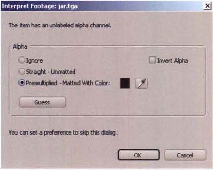
The program also offers the option to pick a different color to be used in the matting process. For instance, if you import a render from Maya that has a green background color, you can set the Matted With Color cell to green and thus carry out a successful premultiplication interpretation. (If the Matted With Color cell doesn't match the background color of the render, the background color will be trapped within a thin line running around the edge of the rendered element.)
In general, any imported 3D render should be interpreted as premultiplied. However, on occassion it becomes useful to ignore the premultiplication. For example, CG glow, fog, and optical effects may retain better edge quality when the Straight radio button is selected. To avoid having After Effects prompt you for alpha interpretation, choose Edit → Preferences → Import, and change Interpret Unlabeled Alpha As to the interpretation of your choice.
After Effects offers the following additional support for alpha:
When rendering through the Render Queue, you can choose to render an alpha channel by changing the Channels menu in the Output Module Settings dialog box to RGB + Alpha (assuming the selected image format supports alpha). In addition, you can choose to render premultiplied or straight files by changing the Color menu to Straight (Unmatted) or Premultiplied (Matted). Straight files may be required when importing the After Effects output into another program, such as an editing software that doesn't support premultiplication.
You can view the alpha channel in the viewer of the Composition panel at any time by changing the Show Channel menu to Alpha.
It's possible to invert the alpha channel by choosing Effect → Channel → Invert and changing the effect's Channel menu to Alpha. What was opaque becomes transparent and vice versa.
The TrkMat (Track Matte) menus, which are visible when the Toggle Switches/Modes button is clicked, offer a quick way to cut a hole into the alpha of a layer. For example, you can set a layer's TrkMat menu to the name of a hidden layer that is directly above. The named layer's alpha or RGB luminance values are converted to new alpha values for the layer whose TrkMat menu was set.
Each layer of each composition receives its own blending mode. The blending mode determines how the layer will be blended with the net result of the layers below it. By default, the blending mode is set to Normal. However, there are two ways you can change a layer's mode:
RMB+click over the layer's name in the layer outline of the Timeline panel. Choose Blending Mode → blending mode (see Figure 3.11).
Click the Toggle Switches/Modes button at the bottom-left of the Timeline panel. This reveals the Mode menus beside each layer (see Figure 3.11). Change each menu to the blending mode of your choice.

Figure 3.11. (Top) A small section of the Blending Mode menu (Bottom Left) Toggle Switches/Modes button (Bottom Right) Mode menus for two layers in the layer outline
Commonly-used blending modes are described in the section "Fundamental Math Operations" earlier in this chapter. For additional documentation on the remaining blending modes, see the "Blending Mode Reference" page in the After Effects help files.
Keying effects in After Effects are broken into two categories: keyers (Effect → Keying) and chokers (Effect → Matte). While keyers remove unwanted color from bluescreen or greenscreen plates, chokers refine the resulting alpha matte edges.
Simple Choker is designed to erode or expand the edge of a matte. It has a Choke Matte slider, which controls the amount of erosion or expansion.
Matte Choker offers the same erosion or expansion but provides greater control. Two sets of Choke sliders are supplied to erode or expand the matte. For example, you can use Choke 1 to expand the matte and thus fill small holes (see Figure 3.12). At the same time, you can use Choke 2 to erode the matte to improve the outer edges. It's not necessary to use both Choke sliders. If Choke 1 produces acceptable results, Choke 2 can be left at 0. Values above 0 for either Choke slider erode the matte (that is, reduce the number of pixels with 1.0 alpha values). Values below 0 for either Choke slider expand the matte. In addition, each Choke has a Gray Level Softness slider which controls the amount of blur applied to the matte edge. (Gray Level Softness 2 must be above 0 for the blur to appear.) High values will anti-alias the matte edges but tend to round off any sharp corners. In addition, each Choke has a Geometric Softness slider that sets the aggressiveness of the erosion or expansion.
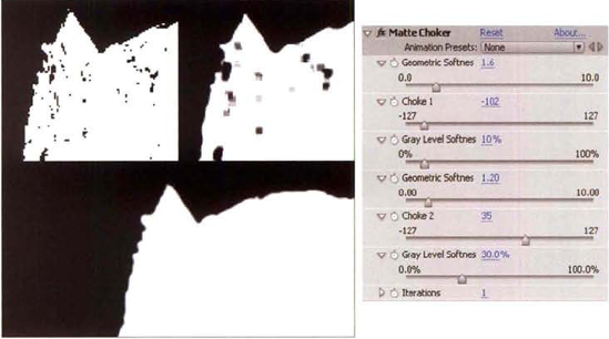
Figure 3.12. (Top Left) Close-up of alpha matte with hard edges and holes (Top Center) Same matte after Matte Choker is applied with default settings (Bottom Left) Matte Choker adjusted to smooth edge and remove holes (Right) Adjusted matte choker settings. A sample After Effects project is saved as matte_choker.aep in the Tutorials folder on the DVD.
Since keyers are unable to provide clean matte edges in some situations, Simple Choker and Matte Choker can give you an extra level of control. In addition, you can easily remove stranded pixels with either effect. For demonstrations of both effects, see the next section, plus the section "Difference Matte" later in this chapter.
The Color Key, Linear Color Key, and Luma Key effects target specific value information within an image. The values may be expressed as color, hue, chroma, or luminance.
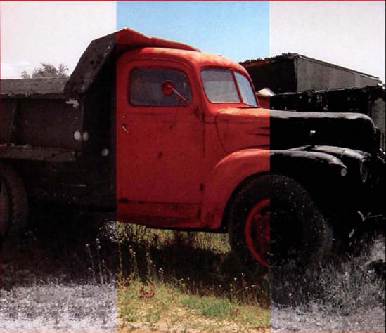
The Color Key effect bases its matte creation on a color established by its Key Color swatch. You can choose any color found within the image with the associated eyedropper. The keyer is suited for footage in which the background color does not appear in the foreground object. For example, in Figure 3.13, the proper exposure for a building face has left the sky overexposed. The Color Key keyer, in conjunction with a Matte Choker, is able to remove the sky without affecting the building's windows. With the Color Key effect, you can refine the aggressiveness of the matte by adjusting the Color Tolerance slider. The higher the Color Tolerance value, the wider the color range targeted for keying. You can erode or expand the matte with the Edge Thin slider. You can soften the edge with the Edge Feather slider. The Edge Feather slider can help disguise stair-stepped edges, which the keyer is prone to.
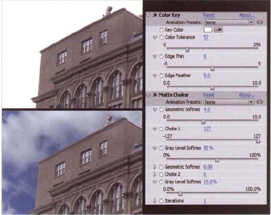
Figure 3.13. (Top Left) Building with overexposed sky (Bottom Left) Footage composited over a new sky after application of Color Key and Matte Choker (Right) Color Key and Matte Choker settings. A sample After Effects project is saved as color_key.aep in the Footage folder on the DVD.
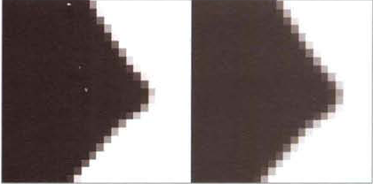
Whereas Color Key simply keys out any color that matches the color determined by the Key Color option, Linear Color Key bases pixel transparency on the closeness of the color match. In other words, Linear Color Key is able to apply falloff to the pixel transparency. For example, in Figure 3.14, a Color Key matte is compared to a Linear Color Key matte. When the Color Key has it Edge Feather left at 0, the edge reveals the binary (on/off) nature of the keyer. When Edge Feather is raised, the edge becomes softer, but the softness is equal at all edge points. Linear Color Key, in comparison, tapers the pixel transparency based on pixel color value. To make the taper more gradual, you can increase the Linear Color Key's Matching Softness slider.
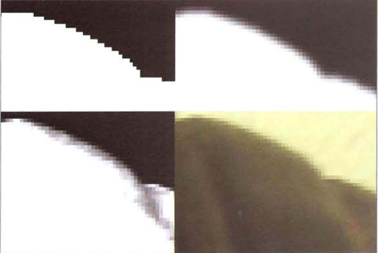
Figure 3.14. (Top Left) Alpha matte edge produced by Color Key (Top Right) Edge produced by Color Key with a high Edge Feather value (Bottom Left) Edge produced by Linear Color Key (Bottom Right) Close-up of plate
The Linear Color Key effect adds the ability to match colors through RGB, Hue, or Chroma color spaces, as set by the Match Colors menu. RGB causes Linear Color Key to operate in the same space as Color Key. Hue, on the other hand, forces the examination of pixel hue while ignoring saturation values. Chroma operates on the color purity of a pixel. Although RGB works for most situations, Hue and Chroma may be desirable when the color to be removed is very saturated or has a narrowly-defined value. The Linear Color Key effect's Matching Tolerance slider operates in a manner similar to the Color Key effect's Color Tolerance slider.
The Luma Key effect bases its matte creation on image luminance. The keyer can affect brighter, darker, similar, or dissimilar pixels through its Key Type menu. The keyer is useful for any image that carries extreme variations in luminance levels. For example, in Figure 3.15, the fire from a burning structure is separated from its background. With the Luma key effect, you determine the targeted luminance value with the Threshold slider. The Tolerance slider sets the width of the luminance range. Edge Thin and Edge Feather control the erosion and softness of the matte.

The Color Difference Key effect divides the image into intermediate mattes and recombines them into a final alpha matte. Although it bases its functionality on common color difference key techniques (see the section "Common Approaches to Keying" earlier in this chapter), its workflow is unique:
A color is selected through the Key Color eyedropper.
Intermediate mattes Partial A and Partial B are created automatically. Partial B bases it transparency on the Key Color hue. (The operation occurs in HLS, or Hue/Lightness/Saturation, space.) Partial A bases its transparency on a hue offset on the HLS color wheel.
Partial A and Partial B are adjusted through A and B sliders, which include In White, Out White, In Black, Out Black, and Gamma. The sliders have the effect of setting the white and black points for the partial mattes. (For information on white and black points, see Chapter 2.) The points can also be set by clicking the A or B buttons below the small matte preview window and using the White eyedropper or Black eyedropper (see Figure 3.16). In addition, you can preview the mattes in the viewer of the Composition panel by changing the View menu to Matte Partial A Corrected, Matte Partial B Corrected, or Matte Corrected. (Matted Corrected displays the final combined matte.)
The final matte is automatically generated by blending Partial A with Partial B in a screen blending operation. No alpha values are allowed to exceed a normalized 1.0. Final adjustments to the alpha matte can be made with the Matte In White, Matte In Black, and Matte Gamma sliders.
Although the Color Difference key is fairly unintuitive, it does offer the advantage of partial mattes. By using two partial mattes, you can maintain fine edge quality without the risk of opening up holes in the main body of the foreground objects. That is, you can adjust one matte to protect the interior of the object and ensure that it appears solid; at the same time, you can adjust the second matte to keep feathered edges. For example, in Figure 3.16, clouds are separated from the sky and composited over a new background.

Figure 3.16. (A) Sky plate (B) New background image (C) Alpha channel created by Color Difference Key (D) Final composite (E) Close-up of matte preview window with A and B buttons and white and black point eyedroppers (F) Color Difference Key settings. The clouds have been color graded toward red. A sample After Effects project is saved as color_difference_key.aep in the Tutorials folder on the DVD.
The Color Range effect keys out a specific range of colors in L*a*b* (Lab), YUV, or RGB color space. The range of colors keyed out is centered on a single color chosen by the user through the Key Color eyedropper (see Figure 3.17). The range is then adjusted with a Min and Max slider for each channel (L, a, b or Y, U, V or R, G, B) or by sampling pixels with Plus or Minus eyedroppers. Color Range is useful for removing unevenly lit greenscreen or separating foreground elements that differ in color. For example, in Figure 3.17, a long-exposure night shot features spinning green lights beside the orange and yellow lights of a tent. The green is isolated from the rest of the frame by applying a Color Range and Invert effect.

Figure 3.17. (Top Left) Long-exposure night photo (Top Right) Photo after application of Color Range effect. (Bottom Left) Color Range settings. A sample After Effects project is saved as color_range.aep in the Tutorials folder on the DVD. (Bottom Right) Default Extract effect settings.
The Extract effect functions in a similar manner to the Color Range effect but keys out a particular value range of a single channel. The range is determined by changing the Channel menu to Luminance, Red, Green, or Blue and determining the White Point (white threshold) and Black Point (black threshold) values for that channel (see Figure 3.17). Extract is the most useful when keying out a background that has a luminance significantly different from the foreground.
The Difference Matte effect compares a source layer with a difference layer and keys out pixels in the source layer that don't match corresponding pixels in the difference layer. Generally, the source layer contains an object against a background and the difference layer contains the same background without the object. The Difference Matte effect doesn't require a background with a particular color, although the technique would work with chroma key footage. The Difference Layer menu selects its namesake. The Tolerance slider determines the range of pixels that are assigned an alpha value of 1.0. The higher the Tolerance value is, the more accurate the match between source and difference layer pixels must be for pixels to remain opaque. The Matching Softness slider tapers the transition between opaque and transparent pixels. The Blur Before Difference slider applies a blur before creating the matte, which can help reduce noisy artifacts. As an example, in Figure 3.18, a seashell is pulled from an ocean backdrop with the Difference Matte effect. The seashell/ocean layer serves as a source layer and the empty ocean plate serves as the difference layer. Because the effect is prone to create rough edges and trap remnants of shadows, a Simple Choker effect is added. The pulled shell is then composited over a new background.

Figure 3.18. (Top Left) Source layer with seashell over an ocean backdrop (Top Center) Difference layer with the ocean by itself (Bottom Left) Result of Difference Matte (Bottom Center) Final composite (Right) Difference Matte and Simple Choker settings. A sample After Effects file is saved as difference_matte.aep in the Tutorials folder on the DVD.
Keylight, developed by The Foundry, is the most advanced keyer that's bundled with After Effects. In fact, Adobe documentation suggests employing Keylight before utilizing any other keyer. As such, Keylight is demonstrated with the After Effects tutorials included in this chapter.
Inner/Outer Key, due to its limited functionality and relatively poor success rate, should be skipped. Although the keyer provides the means to establish several mattes to control the alpha matte creation, it's just as easy to create your own holdout or garbage masks while using a more robust keyer. For masking approaches, see Chapter 7, "Masking, Rotoscoping, and Motion Tracking."
The Spill Suppressor effect removes trace amounts of key color left on the foreground element after a plate has been keyed. You can choose the color with the Color To Suppress color swatch. You can control the intensity with the Suppression slider. If the foreground has been properly lit, spill suppression is generally not necessary. However, the effect comes in handy for footage shot in nonideal situations (see Figure 3.19).
Nuke automatically reads the alpha channel of any file imported through a Read node. However, Nuke will not interpret the alpha as premultiplied unless the Premultiplied check box is selected in the Read node's properties panel.
Nuke offers the following additional support for alpha:
When rendering through a Write node, you can choose to render an alpha channel by changing the node's Channels menu to Rgba (assuming the selected image format supports alpha).
To render a premultiplied image, select the Premultiplied check box in the Write node's properties panel. If you render a premultiplied image, then re-import the image through a new Read node, the new Read node's Premultiplied check box should be selected to maintain edge quality.
You can view the alpha channel in a viewer at any time by clicking the Viewer pane and pressing the A key. To return to an RGB view, press A again.
It's possible to invert the alpha channel by adding an Invert node (Color → Invert) and changing the node's Channels menu to Alpha.
Images and image sequences are combined in Nuke through the Merge node. Whereas After Effects applies different blending modes to create the combinations, Nuke applies different merge operations through the Merge node. The node's input A is equivalent to layer A, or the top layer. The node's input B is equivalent to layer B, or the bottom layer. The merge operation is set by the node's Operation menu.
Commonly-used merge operations are described in the section "Fundamental Math Operations" earlier in this chapter. For additional documentation on the remaining operations, see the "Merge Operations" section of the Nuke user manual. To quickly examine the math behind each operation, let the mouse hover over the Operation menu; a list of operations and their formulas are displayed in a yellow tooltip box.
There are several ways to apply a Merge node:
Select the node that will serve as input A. Press the M key, which is the default hotkey for the Merge node. The input A of a new Merge node is connected automatically to the selected node. Manually connect input B.
In the Node Graph, RMB+click and choose Merge → Merge. This menu option creates a new Merge node and sets the Operation to Over, which is the same as the Normal blending mode in After Effects.
In the Node Graph, RMB+click and choose Merge → Merges → merge operation. Nine of the most commonly used merge operations are included in this menu.
Although only two input pipes appear on a Merge node by default, the node is not limited to two inputs. If you connect additional nodes to a Merge node, additional input pipes are created; input A is relabeled A1 and the new pipes are labeled A2, A3, and so on. In this situation, the input with the highest A number, such as A2, becomes the "top" input. For example, in Figure 3.20, a CG spaceship and a smoke trail render are merged with a sky plate. Because the spaceship is connected to input A2, it occludes both the smoke trail (input A1) and the sky (input B). Unfortunately, all inputs share the same merge operation. While the use of single merge operation on all the inputs of a Merge node might work fine, it limits the flexibility of the composite. A separate solution requires the connection of two or more Merge nodes. In the case of Figure 3.20, the first Merge node is set to Screen and combines the smoke with the sky. The second Merge node is set to Over and combines the spaceship with the smoke/sky output.
By default, the contribution of input A is 100%. However, you can reduce this by lowering the Merge node's Mix slider below 1.0. If more than two inputs are connected to a Merge node, the Mix slider controls the contribution of all the A inputs. (For additional information on Merge node parameters, see Chapter 7, "Masking, Rotoscoping, and Motion Tracking.")
Of the 30 different merge operations available through the Operation menu, only Matte requires unpremultiplied inputs (that is, values that have not been premultiplied). All other operations expect premultiplied inputs. You can apply premultiplication to a node output at any time by adding a Premult node (RMB+click and choose Merge → Premult). To remove the premultiplication from a node, add an Unpremult node (Merge → Unpremult). The various Nuke tutorials in this book use Merge and Premult nodes regularly.

Figure 3.20. (Top Left) Three Read nodes connected to a single Merge node (Top Right) Resulting composite. A sample Nuke script is included as multi_input.nk in the Tutorials folder. (Bottom Left) Three Read nodes connected to two Merge nodes with different Operation settings (Bottom Right) Resulting composite. A sample Nuke script is included as multi_merge.nk in the Tutorials folder on the DVD.
Several other nodes are able to undertake input blending. These are available through the Merge menu:
Blend averages the values of two inputs. By default, the contribution of each node is 50%. However, you can bias one over the other by adjusting the 1 and 2 sliders. For example, raising the 1 slider above the value of 1.0 biases the input 1; input 2 becomes dimmer and more transparent.
Dissolve averages the values of two inputs. The balance between the inputs is controlled by the Which slider. If Which is set to 0.5, the output is a 50% mix of both inputs. If Which is set to 0, only input 0 is visible. If Which is set to 1.0, only input 1 is visible.
Time Dissolve averages inputs in the same manner as Dissolve. However, instead of providing a Which parameter, Time Dissolve provides an interactive curve and curve editor that changes the dissolve over time. When the curve has a 1.0 value, input B is biased. When the curve has a value of 0.5, input A and input B are mixed. Note that the horizontal axis of the editor runs from 0 to 1.0 and represents the full frame range. The specific start and end frames are set by the In and Out cells. You can move a curve point by LMB+dragging a point in the editor. You can insert a new point by selecting the curve so that it turns yellow and Ctrl+Alt+clicking on the curve.

Figure 3.21. (Top Left) Default AddMix settings (Top Right) Result of default settings (Bottom Left) Color correction curve A is adjusted to form an arc. (Bottom Right) Result of adjusted curve. The edge of the smoke becomes brighter and more opaque. A sample Nuke script is included as
addmix.nkin the Tutorials folder on the DVD.AddMix supplies a curve editor and creates a color correction curve for the alpha of input A and the alpha of input B. The A curve is multiplied against the A alpha and the B curve is multiplied against the B alpha before the two alpha channels are added together. The ability to alter the curves allows you to fine tune matte edges and alpha opacity. By default, both curves run from 0 to 1.0, although the B alpha curve is inverted so that is has an opposite slope. You can edit the curves in the same manner as you would with the Time Dissolve curve editor (see the previous paragraph). As an example, in Figure 3.21 a CG smoke trail is blended with a sky plate. The Read1 node, which carries the smoke, is connected to the input A of the AddMix1 node. The Read2 node, which carries the sky plate, is connected to the input B. Because the smoke render was premultiplied by the 3D program, the Read1 node's Premultiplied check box is selected. In addition, the AddMix1 node's Premultiplied check box is selected; this forces the AddMix1 node to unpremultiply input A before multiplying color correction curve A. By adjusting the shape of color correction curve A in the curve editor, variations in the alpha matte edge quality can be achieved.
KeyMix reveals input A within the mask area established by the node's Mask input. For more information on masking, see Chapter 7, "Masking, Rotoscoping, and Motion Tracking."
CopyRectangle isolates a rectangular section of input A. The node is designed to limit an effect to a particular region of an input, then merge the result with the original, unaffected input. For example, in Figure 3.22, the output of a Read node is connected to a Blur node. The Blur node output is connected to the input A of a CopyRectangle node. The output of the Read node is also connected to the input B of the CopyRectangle node. The result is a blur confined to a rectangular region. The CopyRectangle node provides an interactive rectangular region box. To move the box, LMB+drag the box center in the viewer. To resize the box, LMB+drag one of the four box edges.
MergeExpression allows you to write your own blending mode math with expressions. For an introduction to expressions in Nuke, see Chapter 12, "Advanced Techniques." For examples of common blending mode formulas, see the "Fundamental Math Operations" section earlier in this chapter.
ZMerge creates a blend based on a depth channel. For a demonstration, see Chapter 9, "Integrating Render Passes."

Nuke includes six nodes designed for keying. Each has its own advantages and disadvantages.
The Difference node outputs an alpha matte after identifying the difference in RGB pixel values between two inputs. Pixels that are identical are assigned 0 alpha values. Pixels that are different are assigned alpha values that range from 0 to 1.0 based on the degree of difference. The RGB output of the Difference node is taken from the B input of the node. For example, in Figure 3.23, a green-blue gradient is connected to the input B of a Difference node. The word test, with red, green, blue, and white letters over the same gradient, is connected to the input A of the Difference node. The output of the node is connected to a Premult node and, in turn, to a viewer. The result is the gradient cut out in the shape of the word test. Each letter does not contain 1.0 alpha values, however. The E and S have alpha values of 0.48 and 0.58 respectively; this is due to green and blue colors of the letters possessing values relatively close to those of the green-blue gradient.

The IBKGizmo and IBKColour nodes are two components of an image-based keyer. Whereas color-based keyers base their matte extraction on a baseline color selected by the user (such as blue or green), image-based keying compares pixel values.
The IBKColour node Gaussian-blurs chroma key footage and extracts a hicon (high-contrast) matte. Contrast is determined by comparing the key color, set by the Screen Type menu in the IBKColour properties panel, and the remaining scene colors. Ideally, the RGB output of the node contains only the key color. The output of the IBKColour node is designed to feed into the C (color) input of an IBKGizmo node. The original chroma key footage must be connected to the FG input of the IBKGizmo node. The IBKGizmo node generates a difference matte from the original chroma key footage and IBKGizmo's blurred output. The output of IBKGizmo may then be combined with the new background plate with a Merge node.
For example, in Figure 3.24, a fish is composited over a fish tank. The fish footage is connected to the input of an IBKColour node and the FG input of an IBKGizmo node. The IBKGizmo node's Screen Type menu is set to match the IBKColour node's Screen Type menu; in this case, IBKColour is set to Green and IBKGizmo is set to C-green. Since the default setting for IBKColour did not create a completely clean matte, the Darks/g cell is set to −0.1.

Figure 3.24. (Top Left) Greenscreen fish footage (Top Center) RGB output of IBKColour node (Top Right) Final composite (Bottom Left) Node network (Bottom Right) IBKColour and IBKGizmo settings. A sample Nuke script is included as ibk.nk in the Tutorials folder on the DVD.
The Darks and Lights RGB cells are designed to adjust the upper and lower color thresholds for the matting process. A Darks/g value of −0.1 removes holes appearing in the center of the matte. However, to refine the matte edge, which is not aligned tightly enough to the fish body, the output of the IBKGizmo node is connected to an Erode (Blur) node. The Erode (Blur) node erodes the matte. To create a correct composite, however, the output of the Erode (Blur) node is connected to a Premult node, which is in turn fed into a HueCorrect node. Without a Premult node, the Erode node would create a fine line around the edge. The HueCorrect node simply color-adjusts the fish to match the tank lighting. The output of HueCorrect finally runs into a Merge node, which combines the fish and the fish tank plate.
As demonstrated in the Chapter 1 Nuke tutorial, the Keyer node offers a simple way to generate an alpha matte. As determined by its Operation menu, the Keyer can base its output on luminance, greenscreen color, bluescreen color, saturation, minimum value, maximum value, or values within specific RGB channels. Targeted values are controlled by a Range graph (see Figure 3.25). You can LMB+drag the yellow handles to fine-tune the matte. The lower-left handle determines the threshold for transparent pixels (the graph scale is normalized from 0 to 1.0). As you drag the handle to the right, pixels with values lower than the handle value are assigned 100% transparency (an alpha value of 0). For instance, if Operation is set to Saturation Key and the handle value is 0.3, then any pixel with a saturation value less than 0.3 (or 30%) becomes transparent. The upper-right handle of the Range graph sets the threshold for opaque pixels. Any pixel with a value higher than the handle is assigned an alpha value of 1.0. The angle of the curve between the lower-left and upper-right handles determines the degree of falloff from transparent to opaque pixels. A steep slope produces a more severe transition. When the upper-right handle is moved aside, it reveals a third handle in the same position. The third handle sets the upper value limit for pixels that are assigned an alpha value of 1.0. If the second handle is set to 0.5 and the third handle is set to 0.75, then pixels with values between 0.5 and 0.75 receive alpha values of 1.0.

Figure 3.25. (Top Left) Matte produced by the Keyer node (Bottom Left) Resulting composite over a new sky plate (Top Right) Keyer node network (Bottom Right) Keyer effect's properties panel with Range graph. A sample Nuke script is included as keyer.nk in the Tutorials folder on the DVD.
As a working example, in Figure 3.25 a sky is keyed from a plate with a building. Since the Keyer node did not produce a clean edge on the matte, its output is sent through an Erode (Blur) node. In order to successfully use the resulting matte with a Merge node, the Erode (Blur) node's output is sent through a Premult node. Because the sky is significantly brighter than the building, the Keyer node removes the building until the node's Invert check box is selected.
The HueKeyer node bases its alpha matte on a color range interactively selected through its built-in curve editor. Two curves are provided: Amount and Sat_thrsh (Saturation Threshold). Hues from the input are presented left to right. If an Amount curve point is raised to 1.0, then the corresponding hue is keyed out. That is, the hue receives an alpha value of 0 while the remainder of the image receives a value of 1.0. (You can reverse this behavior by deselecting the Invert check box.) If an Amount curve point is positioned between 0.1 and 1.0, the corresponding hue receives semitransparent alpha values. The Sat_thrsh curve establishes the sensitivity of the key operation. The higher a Sat_thrsh curve point is raised above its default 0.1 value, the greater the saturation a pixel must carry of a particular hue to receive low alpha values. For example, in Figure 3.26, a crayfish is removed from its surroundings with a HueKeyer node. The Amount and Sat_thrsh curves are shaped to target the orange red of the creature. The Invert check box is deselected. Since the HueKeyer is unable to remove the white foam and sections of the black pot that contain red, green, and blue values equally, the HueKeyer output is connected to a Blur and Grade mode, both of which are set to operate on the alpha channel only.

With the Chapter 2 tutorials, you had the opportunity to remove a greenscreen from a statue. There are several areas in which the greenscreen removal can be improved. Since Tutorial 2 featured an inanimate object, the chroma key challenges are fairly mild. Hence, additional After Effects and Nuke tutorials are included in this chapter that use video footage of a model.
Although the greenscreen removal undertaken in Chapter 2 was fairly straightforward, the color balance of the statue and edge quality of the alpha matte can be improved.
Reopen the completed After Effects project file for "AE Tutorial 2: Working with DPX and Cineon Files." A finished version of Tutorial 2 is saved as
ae2.aepin the Chapter 2 Tutorials folder on the DVD. At this stage, the edge of the statue remains sharper than the edges of surrounding buildings. To soften it slightly, select thegreenscreen.cinlayer and choose Effect → Matte → Matte Choker. In the Effect Controls panel, set Choke 1 to 25 and Gray Level Softness 1 to 40%. To view a before image and an after image, click the small Fx button beside the Matte Choker name in the Effect Controls panel. The Matte Choker erodes the edge slightly and creates a greater taper between transparent and opaque pixels (see Figure 3.27).At this stage, the statue remains heavily saturated. To fit the statue into the environment better, select the
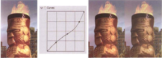
greenscreen.cinlayer and choose Effect → Color Correction → Curves. In the Effect Controls panel, shape the Curves effect's RGB curve to match Figure 3.28. You can LMB+click the curve to insert a new curve point and then LMB+drag the point to a new position. This reduces the brightness in a non-linear fashion. (For more information on color correction effects, see Chapter 4.)Although the statue's brightness better matches the background, the colors remain too saturated for the environment. To remedy this, select the
greenscreen.cinlayer and choose Effect → Color Correction → Hue/Saturation. In the Effect Controls panel, set the Master Saturation slider to −40. Save the file under a new name. The tutorial will be revisited in Chapter 10, where shadows and text will be added. A finished revision is saved asae2_step2.aepin the Tutorials folder on the DVD.
Although the greenscreen removal undertaken in Chapter 2 was fairly straightforward, the color balance of the statue and edge quality of the alpha matte can be improved.
Reopen the completed Nuke project file for "Nuke Tutorial 2: Working with DPX and Cineon Files." A finished version of Tutorial 2 is saved as
nuke2.aepin the Chapter 2 Tutorials folder on the DVD. At this point, the two Log2Lin nodes used to convert the DPX and Cineon files are left at their default settings. You can adjust the Black (black point), White (white point), and Gamma sliders to fine-tune the color quality of the log-to-linear conversions. For example, to improve the opacity and brightness of the fire element, set the Log2Lin2 node's Gamma parameter to 1.0. To reduce the brightness and improve the contrast of the statue, set the Log2Lin1 node's White to 700 and Gamma to 0.5. (For more information on black and white points, see Chapter 2.)Despite the adjustment of the Log2Lin nodes, the statue's color, saturation, and brightness do not match the background plate. To solve this, select the Keyer1 node in the Node Graph, RMB+click, and choose Color → HueCorrect. The HueCorrect node allows you to alter saturation and luminance precisely throughout the full range of hues. Open the HueCorrect1 properties panel, and select the word r_sup in the left column. The r_sup (red suppression) control affects red, green, and blue channels but provides a suppression curve for only the red channel. (For more information on the HueCorrect node, see Chapter 4.) LMB+drag the curve points to form a curve shape similar to the one in Figure 3.29. The heavy red cast disappears. The statue remains too bright, however. Select the word lum in the left column. This displays the luminance curve. Select the entire lum curve by LMB+dragging a selection box around the all the curve points. LMB+drag the selected points downward so that the curve sits at approximately 0.7 (see Figure 3.29).
At this stage, the statue's edge remains very sharp. Select the HueCorrect1 node, RMB+click, and choose Filter → Erode (Blur). An Erode (Blur) node is inserted between the HueCorrect1 and Premult1 nodes. Open the Erode1 node's properties panel, set the Channels menu to Alpha, and adjust the Size and Blur sliders until the statue edge is slightly softened (see Figure 3.30). To see the effect of the node, use the Alt+MMB camera control to zoom into the statue edge in the viewer. Size controls the amount of edge erosion and Blur adds its namesake to the result. If the statue is supposedly eight stories tall and several hundred yards from the camera, its edge would not be perfectly sharp. Compare the statue's edge to the edges of neighboring buildings. A Size value of 1.6 and a Blur value of 0.65 work well. Save the file under a new name. The tutorial will be revisited in Chapter 10, where shadows and text will be added. A finished revision is saved as
nuke2_step2.nkin the Tutorials folder on the DVD.

Keying out the greenscreen of a live-action shoot always has its challenges. Nevertheless, the Keylight effect offers a robust solution for the chroma key process.
Create a new project. Choose Composition → New Composition. In the Composition Settings dialog box, change the Preset menu to HDV/HDTV 720 29.97. Set Duration to 150 frames and Frame Rate to 30. Import the
phonecall.###.tgasequence from the Footage folder on the DVD (see Figure 3.31).LMB+drag the
phonecall.###.tgafootage from the Project panel to layer outline of the Timeline panel. Review the frames by scrubbing through the timeline. The most challenging aspect of this chroma key removal will be saving the fine hairs on the model's head. In anticipation of this, Comp 1 will be dedicated to creating a custom luma matte.With the layer selected in the layer outline, choose Effect → Color Correction → Hue/Saturation. In the Effect Controls panel, reduce the Saturation slider to −100. Select the layer again and choose Effect → Color Correction → Curves. Shape the curve to match Figure 3.32. With the custom curve, you can impart greater contrast to the image, yet maintain some of the fine detail along the hair's edge. You can insert new points into the curve by LMB+clicking on the curve line. To move a point, LMB+drag it. (For more information on color correction effects, see Chapter 4.)
With the layer selected in the layer outline, choose Effect → Channel → Invert. The RGB is inverted so that the hair becomes white 0and the background becomes black (see Figure 3.32).
Create a new composition. LMB+drag Comp 1 from the Project panel to the layer outline of the Comp 2 tab in the Timeline panel. Toggle off the Video layer switch beside the Comp 1 layer so that it is not visible in the viewer of the Composition panel. LMB+drag a new copy of the
phonecall.###.tgafootage from the Project panel to the Comp 2 layer outline and place it below Comp 1. With thephonecall.###.tgalayer selected within Comp 2, choose Effect → Channel → Set Matte. In the Effect Controls panel, change the Take Matte From Layer menu to Comp 1. Change the Use For Matte menu to Luminance. In this situation, the Set Matte effect converts the luminance information from Comp 1's RGB channels into alpha information for thephonecall.###.tgalayer.Since the hair contains a great deal of green, select the
phonecall.###.tgalayer and choose Effect → Keying → Spill Suppressor. Change the effect's Color To Suppress to the greenscreen color (see Figure 3.33). As a final touch for the layer, choose Effect → Color Correction → Brightness & Contrast and Effect → Blur & Sharpen → Channel Blur. Change the Brightness & Contrast effect's Brightness slider to 10 and the Contrast slider to 10. Change the Channel Blur effect's Alpha Blurriness to 4. This softens the matte edges and adjusts the edge highlights.LMB+drag a new copy of the
phonecall.###.tgafootage from the Project panel to the Comp 2 layer outline; place it above the previous footage layer so that it's numbered 2 in the layer outline (see Figure 3.34). With the new layer selected, choose Effect → Keying → Keylight. In the Effect Controls tab, use the Screen Colour eyedropper to select the greenscreen color. The green is removed. Since the model's hair was carefully matted on its own layer in steps 5 and 6, her hair will look normal despite heavy erosion by Keylight. In order to see the composite more clearly, create a new Solid and place it at the bottom of the Comp 2 layer outline. To do so, choose Layer → New Solid, select light red as a new color in the Solid Settings dialog box, click OK, and drag the new Solid layer from the top of the layer outline to the bottom of the layer outline.In this situation, Keylight works fairly well with the remaining options set to default values. However, to fine-tune the keyer, change Keylight's View menu to Status. Status places the viewer in a special mode that indicates pixel values of the alpha matte (see Figure 3.35). White pixels are opaque. Black pixels are transparent. Gray pixels are semitransparent. Green pixels represent green chroma key spill. To reduce and remove the gray pixels appearing where the greenscreen once rested, set the Clip Black slider (in the Screen Matte section) to 50. Any key color pixel encountered with an alpha value below the slider value is assigned a new alpha value of 0. To remove gray pixels from white, opaque areas, set the Clip White slider to 80. Any foreground pixel encountered with an alpha value above the slider value is assigned a new alpha value of 1.0. To soften the edge of the alpha matte and disguise interlacing artifacts along the model's left arm, set the Screen Pre-Blur property to 5.
Return Keylight's View menu to Final Result. With the topmost
phonecall.###.tgalayer selected, choose Effect → Matte → Simple Choker. In the Effect Controls panel, set Choke Matte to 1.4. This erodes away the lines along the edge of the chair and the model's arms. Since the luma matte was employed on a lower layer, the erosion does not affect the detail within the hair.At this point, a dark line remains along the model's left arm (see Figure 3.36). To remove the line, as well as repair the reflective arms of the chair, it will be necessary to divide the footage into multiple sections using masking tools. This will be addressed in the Chapter 7 After Effects follow-up tutorial. In the meantime, save the file under a new name. A sample project is saved as
ae3.aepin the Tutorials folder on the DVD.


Figure 3.35. (Top) Result of the Keylight effect with the View menu set to Status (Bottom) Same view after the adjustment of the effect's Clip Black and Clip White sliders

Figure 3.36. Detail of the final composite. The extraneous pieces of wall, holes in the chair arms, and dark line on the model's left arm will be removed in the Chapter 7 After Effects follow-up tutorial.
Keying out the greenscreen of a live-action shoot always has its challenges. Nevertheless, the Primatte node offers a robust solution for the chroma key process. (If you are using the Nuke PLE and don't have access to the Primatte node, other keyer nodes can produce similar results.)
Create a new script. Choose Edit → Project Settings. Change Frame Range to 1, 150 and Fps to 30. With the Full Size Format menu, choose New. In the New Format dialog box, set Full Size W to 1280 and Full Size H to 720. Enter a name, such as HDTV, into the name cell and click OK.
In the Node Graph, RMB+click and choose Image → Read. Browse for and select the
phonecall.###.tgasequence from the Footage folder on the DVD. Connect a viewer to the Read1 node to preview the greenscreen footage.With the Read1 node selected, RMB+click and choose Keyer → Primatte. The Read1 node is automatically connected to the FG input of the Primatte1 node. With no nodes selected, RMB+click and choose Draw → Rectangle. Connect the BG input of the Primatte1 node to the output of the Rectangle1 node. Use Figure 3.37 as a reference. Open the Rectangle1 node's properties panel and change Area X to 1280, Area Y to 720, Area R to 0, and Area T to 0. Switch to the Color tab and change Color RGBA to 1, 0.5, 0.5, 1. The light red rectangle will allow you to check the edge quality of the alpha matte while working with Primatte.
Open the Primatte1 node's properties panel (see Figure 3.37). Click the Auto-Compute button. Auto-Compute undertakes the initial keying steps. It attempts to identify the chroma key color, keys out that color, and nullifies any background and foreground noise. With the
phonecall.###.tgafootage, Auto-Compute is successful at removing the greenscreen. However, the model's hair is eroded (see Figure 3.38).To improve the result of Auto-Compute, click the Reset button (which removes the key), change Auto BG Factor and Auto FG Factor to −0.5, and click the Auto-Compute button again. This time, the greenscreen is partially removed, but the hair remains intact (see Figure 3.38). Auto BG Factor sets Auto-Compute's aggressiveness toward removing noise found in the background, while Auto FG Factor does the same for foreground noise. The higher the values, the more the noise will be suppressed but the higher the likelihood that fine details of the foreground will be lost.
The Auto-Compute routine is optional. If you'd like to select the key color manually, click the Reset button, change the Operation menu to Select BG Color, and select the eyedropper box below the Operation menu. (If the box is selected, it displays an eyedropper icon.) In the viewer, Ctrl+LMB+drag along a section of greenscreen. You can also Ctrl+Shift+LMB+drag to create a selection box. As soon as a color is detected, Primatte keys it out of the image. Note that the manual selection will not employ noise removal. You can employ your own noise removal by changing Type (in the Degrain section) to Small, Medium, or Large and adjusting the Tolerance setting. Higher values reduce the presence of noise and further erode the matte edges.
To fine-tune the matte, click the Viewer pane and press the A key. The alpha is revealed (although the alpha from the rectangle is not included). Change the Operation menu to Clean BG Noise. (Note that the eyedropper should remain visible in the box below the Operation menu.) Ctrl+LMB+drag over the brightest pixels within the greenscreen area. Pixels with the value that you sample are assigned an alpha value of 0. You can repeat the process multiple times. It's not necessary to select every single non-black pixel. Instead, try to balance the removal of the greenscreen with the maintenance of the hair detail.
To improve the alpha of the foreground, change the Operation menu to Clean FG Noise. Ctrl+LMB+drag over the darkest pixels within the silhouette of the model in the viewer. Pixels with the value that you sample are assigned an alpha value of 1.0. It's not necessary to drag over every single non-white pixel, but you should strive to make the model and chair white without destroying the detail along their edges (see Figure 3.39). (It will be extremely difficult to make the arms of the chair opaque while keeping the greenscreen transparent. The chair's wood strongly reflects the greenscreen. Thus, rotoscoping will be required to repair these problem areas. Steps to undertake this are discussed in the Chapter 7 Nuke follow-up tutorial.
Return to an RGB view in the viewer by pressing the A key again. At this point, there is a great deal of green spill trapped in the hair (see Figure 3.40). To reduce this, change the Operation menu to Spill(-). Ctrl+LMB+drag over strands of hair that are green. The green is removed and the strand color will move toward black. Note that the use of Spill(-) significantly affects the color within the body of hair. If you need to restore the hair detail and thus return some of the spill, change the Operation menu to Spill(+) and Ctrl+LMB+drag over strands of hair that have become too black. Despite the spill operations, you may be left with hair strands that are heavily saturated with green. To remove the green cast, you can change the Primatte basic spill suppression method. By default, Primatte replaces spill color with a complement on the color wheel. However, you can change the Replace With menu (in the Spill Process section) to No Suppression, Solid Color, or Defocused Background. In this case, you can use Solid Color if you change the Replace Color RGB to a brownish-black (see Figure 3.40).
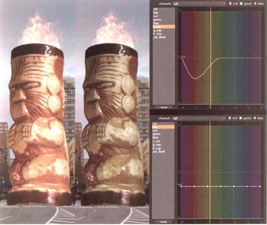
An alternant approach to removing the green spill is to apply a HueCorrect node, which gives you greater control and generally a better result. To do this, return the spill to its previous condition by either choosing Edit → Undo or using the Spill(+) operation. Select the Primatte1 node, RMB+click, and choose Color → HueCorrect. Open the HueCorrect1 node's properties panel. In the curve editor, click on the word g_sup in the left column and LMB+drag the curve point at hue position 3 (green) from a value of 1.0 to a value just above 0 (see Figure 3.41). LMB+drag the curve point at hue position 2 (pale yellow) from a value of 1.0 to a value approximately of 0.75. (Hues run horizontally on a scale of 0 to 6 and values run vertically on a scale of 0 to 2.) This effectively removes the green spill from the hair without damaging the overall hair color. (For more information on the HueCorrect node, see Chapter 4.)
To see the result of the Primatte1 node through a Merge node, you must premultiply its output. To do so, select the HueCorrect1 node, RMB+click, and choose Merge → Premult. To see the result against a colored background, select the Premult1 node, RMB+click, and choose Merge → Merge. Connect the input B of the Merge1 node to the Rectangle1 node. Attach a viewer to the Merge1 node.
If you've managed to refine the matte to maintain the fine details of the hair, odds are that the hair still has a semihard edge or is "lumpy" (see Figure 3.42). To solve this problem, it will be necessary to make a custom luma matte and copy channels between nodes. This will be addressed in the Chapter 4 follow-up Nuke tutorial. In the meantime, save the file under a new name. A sample Nuke script is included as
nuke3.nkin the Tutorials folder on the DVD.


Figure 3.42. Detail of the initial composite. The matte edge will be improved in the Chapter 4 Nuke follow-up tutorial.
Johnathan R. Banta began creating visual effects when he was 9 years old, shortly after seeing the original Star Wars. He started compositing in After Effects in 1996 while at BOSS Film Studios. In 1998, he joined Sassoon Film Design as a lead compositor and digital supervisor. At present, he runs his own visual effects company, Agrapha Productions, and serves as a freelance lead compositor, CG supervisor, and matte painter at various Los Angeles visual effects houses. He's won two VES (Visual Effect Society) awards for his work with IMAX. His credits include over 70 television shows and feature films including Titantic, The Big Lebowski, The West Wing, Smallville, and Revolution. At the time of this writing, Johnathan was working at Zoic Studios as a lead compositor.

Johnathan R. Banta at his Zoic Studios workstation.
Zoic Studios was founded in 2002 by Chris Jones, Steve Schofield, and Loni Peristere. Zoic is known for its visual effects work for episodic television; however, they also provide services for feature films, commercials, and video games. Zoic's credit list includes the shows Buffy the Vampire Slayer, Angel, Battlestar Galactica, and CSI as well as the features The Day After Tomorrow, Spiderman 2, and Van Helsing.

Entrance to the Zoic Studios facility in Culver City. The building was originally constructed for an architectural design firm.
(Zoic currently uses After Effects for episodic television work and Shake for feature film effects.)
LL: How often do you work with greenscreen?
JB: It's very common-more so than bluescreen.
LL: Are there any advantages to bluescreen these days?
JB: Bluescreen comes in occasionally. The problem with bluescreen is that it isn't easy to light because it tends to suck in more light. So, DPs (directors of photography) don't like it. Someone at some point convinced everyone that, because YUV [video]...had more luminance information in the green channel, greenscreen was the better way to go. The problem I personally have with greenscreen is that it is closer to human skin tone than was the blue. The logical thought process that the green record is cleaner than the blue record [is flawed]. Most greenscreen [keyers] use the blue record to pull the matte and you get the noise from the blue record anyway.... As long as I have something well lit and in a common color, I'm happy. That being said, not-very-well-lit is the standard.
LL: Was blue or greenscreen an issue with the IMAX projects you worked on?
JB: I [was] working with documentary people who would say, "This is what we have and this is what we want to do with it." It was rarely set up as a visual effects production. Secondly, you have the pressures of [location]—the wind is blowing, the generator blows out... The "fix it in post" saying, although it's a bit of a joke, it's generally part of the production process.
LL: Do you currently work with "dirty" plates; that is, ones with no bluescreen or greenscreen that nevertheless require effects work?
JB: Yes. We matchmove, rotoscope.... Because of the new radical camera approach where the camera is never locked down or it's always on a Steadicam, far [more] often we're off of our screen, so there's always roto involved. Or, the spill is too great or the lighting wasn't there.
LL: Does Zoic ever send rotoscoping work to another studio?
JB: Zoic has a facility in Canada as well. Sometimes roto goes there. For the most part, at least for the team I'm leading on Fringe, we make sure everybody has rotoscope ability....
LL: Would there be a disadvantage to sending roto out-of-house?
JB: As long as you have quality control, I don't see a disadvantage to that.
LL: When you remove blue or greenscreen, what tools do you use?
JB: I do anything and everything to get a pull. I'll use any procedural method or layering method that I can come up with as well as "pixel mining." I'm very adept at this personally because of what I've had to do on IMAX. I'll find whatever data I can.... Multiple color operations in different color spaces. I'll use Keylight. I'll use Primatte. I'll use whatever gets me there.
LL: Do you use scripting?
JB: I do lots of scripting. I do a lot of JavaScripting.