
"Most people have a mental model of a composite that looks like [a] stack of layers."

Compositing CG elements has its own unique challenges. Of these, the fact that CG is often divided into multiple layers leads to a different compositing workflow than may be present with live-action footage. The process becomes even more complicated when each layer is broken into specific render passes. Common render passes include beauty, diffuse, specular, and shadow. More complex passes, such as depth, motion vector, surface normal, and RGB lights, are not unusual. Although render passes increase the compositor's ability to fine-tune, they also require more complex layer stacks and node networks. With the tutorials in this chapter, you'll have the chance to practice compositing CG that is broken into numerous render passes. At the same time, you'll have the opportunity to relight a CG shot with a single RGB light pass.
When a shot is animated in a 3D program on a professional production, it is rarely rendered out as is. Instead, the shot is divided into layers and/or render passes. Dividing a shot into layers allows key elements—including characters, backgrounds, shadows, effects, and props— to be rendered separately. By dividing the shot into layers, you gain efficiency. Not only do the separate layers render faster than the complete shot, but revising the shot becomes easier because a specific layer can be re-rendered without affecting other layers. With this method, the background can be held with a single frame if the shot has a static camera. Since background models, whether they are an outdoor environment or an indoor set, are often the most complex part of a CG scene, they are therefore the most time-consuming to render.
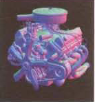
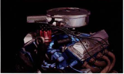
Render passes take the division further by breaking down each layer into specific shading components, light contributions, shadowing effects, or compositing encoders. Color, diffuse, ambient, and reflectivity are common shading components (see Figure 9.1). The contributions of CG lights may be rendered separately or given unique colors in anticipation of additional processing. Shadows may be isolated from the rest of the scene. Compositing encoders, designed for specialized compositing tasks, include depth, ambient occlusion, reflection occlusion, surface normal, UV information, and motion vector renders.
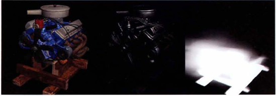
Figure 9.1. (Left) Diffuse pass (Center) Specular pass (Right) Shadow pass (Engine model by Ian Wilmoth)
Render passes give the compositor a great deal of control over the look of the shot. For instance, the intensity of the specular highlight can be increased, reduced, or animated in the composite. In addition, the compositor can insert their own motion blur, depth of field, or atmospheric effects. If light contributions are rendered as passes, the compositor can interactively relight the scene. With proper pass preparation, it's even possible to retexture moving CG elements in the composite.
When a CG shot is rendered as layers, the main difficulty lies in the combination of alpha mattes. For example, if a character is holding a prop yet the character and prop are rendered separately, the renders will not fit together in the composite (see the top left of Figure 9.2). A similar situation arises when two characters are rendered separately but interact closely (hug, shake hands, wrestle, and so on). Fortunately, this can be remedied by applying a form of holdout matte known as an occlusion matte or black hole matte. An occlusion matte is produced by a type of material or material override that renders the assigned object as black and renders the object's alpha channel with 0 (transparent) values. This effectively cuts a hole into any object that sits behind the one assigned to the occlusion matte. As long as the rendered layers are properly premultiplied, they will fit together perfectly (see the bottom right of Figure 9.2). Popular 3D programs and rendering systems all provide some means to create an occlusion matte. For example, Autodesk Maya provides the Use Background material for this purpose. In addition, Maya materials contain a Matte Opacity Mode attribute that can be set to Black Hole. The mental ray renderer provides the Transmat shader, which produces similar results. Autodesk 3ds Max supplies the Matte/Shadow material. A shader used to create an occlusion matte is often referred to as a matte shader.
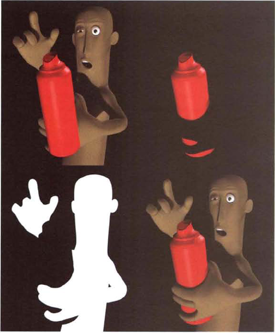
Figure 9.2. (Top Left) Render of spray paint can composited on top of character render (Top Right) Render of spray paint can with occlusion matte material assigned to character (Bottom Left) Alpha channel of render where character is assigned to normal material and occlusion matte material is assigned to the spray paint can (Bottom Right) Composite using occlusion matte passes. A sample After Effects project is included as bloke_matte.ae in the Tutorials folder on the DVD. (Character rig by Jason Baskin. Spray paint model by Ecleposs.)
Many render passes, including beauty, diffuse, specular, shadow, reflection, and depth, may be considered universal because they are commonly used. Other passes, such as ambient occlusion, reflection occlusion, custom holdout mattes, motion vector, UV texture, and various light passes, are common but not mandatory for every project. Note that you will have a chance to combine and composite the majority of these passes in the tutorials at the end of this chapter.
A beauty pass utilizes all the available shading components, lighting contributions, shadowing effects, and render effects (see Figure 9.3). A beauty pass is created by 3D program by default when no render passes are established.
Diffuse, as a term, describes that which is not concentrated but is widely spread. A diffuse surface is one that reflects light rays in a random pattern, thereby preventing a specular highlight from appearing. Real-world diffuse surfaces include paper, cardboard, and dull cloth. A diffuse render pass, on the other hand, has two variations. The first variation contains the surface colors without reference to lighting (see the top right image of Figure 9.3). This variation, also known as a texture pass, must rely on some form of shading pass to give the render a sense of depth and roundness. (Shading refers to the variation of lightness to darkness across a surface.) For example, the shading pass may use the lighting and shadowing established for the beauty pass but assigns gray Lambert materials to the surfaces (see the bottom left image of Figure 9.3). In addition, ambient occlusion and similar skylight passes may be used as shading passes; however, due to their diffuse nature, they cannot contribute any strong sense of directional lighting.
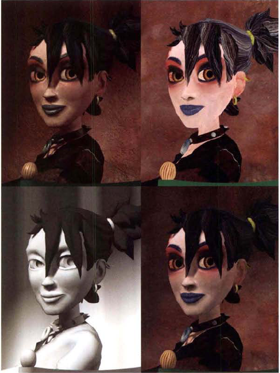
Figure 9.3. (Top Left) Beauty pass (Top Right) Diffuse pass, which lacks shading, specularity, and self-shadowing (Bottom Left) Shading pass (Bottom Right) Diffuse pass multiplied by shading pass. A sample After Effects project is included as girl_diffuse.ae in the Tutorials folder on the DVD.
The second variation of a diffuse pass includes surface color and shading but omits the specular information and self-shadowing (see the top-left image of Figure 9.4). When this variation is combined with a specular pass and a self-shadowing pass, it approximates the beauty pass. A self-shadowing pass is similar to a shadow pass but includes only shadows cast by an object onto itself.
Specular highlights, as created by 3D programs, are artificial constructs. Real-world specular highlights are reflections of intense light sources. 3D surfaces emulate these reflections by increasing the surface brightness where the angle between a reflection vector and view vector is small. A specular pass, also known as a highlight pass, is one that contains the specular "hot spots" over a black background in RGB (see the top-right image of Figure 9.4). Depending on the program and method used to create the pass, it may or may not contain matching alpha channel information.

Figure 9.4. (Top Left) Diffuse pass with surface color and shading component, but no specularity or self-shadowing (Top Right) Specular pass (Bottom Left) The alpha channel of a self-shadowing pass (Bottom Right) Diffuse pass after the merge of the self-shadowing pass and screen blend of the specular pass. A sample After Effects project is included as girl_diffuse_2.ae in the Tutorials folder on the DVD.
A shadow pass" traps" cast shadows in the alpha channel. Since the shadow shape is defined as an alpha matte, the RGB channels are left as black. Shadow passes may include cast shadows and/or self-shadowing. (For a cast shadow example, see Figure 9.1 earlier in this chapter.)
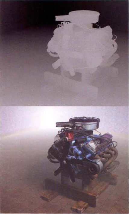
A depth pass, also known as a Z-depth or Z-buffer pass, encodes the distance from the camera to objects within the scene. The encoding takes the form of a grayscale where objects close to the camera have values closer to 1.0 (see Figure 9.5). Depth passes may take the form of a special fifth channel in a Maya IFF or OpenEXR file. Depth passes may also be rendered in parallel to the RGB render. For example, Maya can render the beauty RGB pass as a Targa file and automatically generate a Z-buffer pass as a separate Targa file with a _depth suffix. In either a case, the channel can be viewed only with a program that can properly interpret it (which Photoshop cannot do, but compositing programs can). On the other hand, a specialized material override, such as a depth luminance shader, can render the depth information to standard RGB channels. Depth passes are useful for applying effects that increase or diminish with distance. For example, a depth pass can create an artificial fog that "thickens" with distance (see Figure 9.5).
Holdout matte passes may be used to control specific areas of a CG set, character, or prop. For example, a holdout matte may be generated for the glass of a vehicle (see Figure 9.6). The holdout matte render is then used to isolate the glass within a beauty render. Thus, the glass can be adjusted in the composite separately. Such mattes can be created by assigning material overrides in the 3D program. They can also be generated by rendering an ID pass, whereby a custom attribute, material color, or depth value is assigned to a surface, a set of polygon faces, or a group of objects. Because the elements carry unique values, they can be isolated in the composite. If an ID pass assigns saturated, non-shaded material colors to various elements, it's known as an RGB or RGB ID pass. If an ID pass bases its value on material assignments, it's known as a material ID pass. If an ID pass is based on custom attributes assigned to specific surfaces, it's known as an object ID pass. For examples of ID pass renders, see the section "Using Holdout Matte and RGB ID Passes" later in this chapter.

A reflection pass isolates any reflection or separates reflective surfaces. A refraction pass isolates any refractive surfaces. With both passes, the remainder of the frame is left black in the RGB and transparent in the alpha channel. The passes are useful for creating degraded or blurred reflections and refractions, which would otherwise be expensive to render in the 3D program. Because reflection and refraction passes can be difficult to set up in a 3D program, it is sometimes necessary to create a matching holdout pass. The holdout pass provides occlusion matte information to the passes so that they can fit into the composite without incorrectly covering nearby surfaces. For example, in Figure 9.7, a lamp's reflection and refraction are rendered separately. However, for the glass base to "fit" on top of the beauty render, its upper bend must be cut off with the aid of a holdout pass.

Figure 9.7. (Left to Right) Beauty pass without reflections or refractions; Reflection pass; Refraction pass; Holdout matte pass; final composite. A sample After Effects project is included as lamp_reflect.ae in the Tutorials folder on the DVD. (Lamp by ModelUp Models)
Refraction is the change in direction of a light wave due to a change of speed. When light passes between air, water, glass, and other semitransparent materials, the resulting refraction causes a distorted view. For example, a straw resting in a glass of water appears unnaturally bent below the water line.
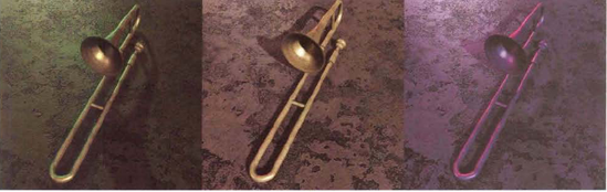
Light passes take several forms. The simplest style of light pass renders a separate beauty pass for each light (see Figure 9.8). The separate beauty passes are then combined in the composite and the individual light contributions are adjusted. The beauty passes can also be color-corrected or tinted for a stylized result.
A second variation of a light pass involves the relighting of the set between beauty renders. For example, one beauty pass is rendered with an initial light setup. The lights are repositioned or adjusted and then a second beauty pass is rendered. This approach is useful when a single lighting setup is not satisfactory for all the objects within in scene.

Figure 9.8. (Top Left) Diffuse pass, with shadows, lit by key light (Top Right) Diffuse pass lit by fill light (Bottom Left) Diffuse pass lit by second fill light (Bottom Right) Three passes combined with masking and color correction. A sample After Effects project is included as engine_lights.ae in the Tutorials folder on the DVD.
A more complex light pass is known as an RGB light pass, where each CG light is assigned to a red, green, or blue primary color. When the RGB light pass render is brought into the composite, each light's illumination is separated by isolating the matching red, green, or blue channel. The light's illumination is then used to create an alpha matte. When the alpha matte is applied to a matching beauty render that uses noncolored lights, the light's contribution to the beauty pass is separated out (see Figure 9.9). The separated light contributions are then recombined. Since each light becomes a separate layer or node, it can be adjusted. Thus it's possible to "turn off" lights, rebalance the intensities of all the lights, and even tint each light a different color.
If a 3D scene contains more than three lights, setting up RGB light passes becomes more complicated. For example, nine lights would require three separate RGB light passes with three lights in each pass. Nevertheless, RGB light passes are easily handled by After Effects and Nuke. Example workflows are included in the tutorials at the end of this chapter.
Ambient occlusion describes the blocking of indirect light. Creases, crevices, and areas around adjacent surfaces of real-world objects are often darker due to the indirect light being absorbed or reflected away from the viewer. You can multiply a beauty or diffuse pass by an ambient occlusion pass to replicate this phenomenon (see Figure 9.10). An ambient occlusion pass occurs in RGB and is identifiable by an overriding white material with a soft, nondirectional shadow.

Figure 9.9. (Top Left) Beauty pass of CG mannequin using three-point lighting (Top Right) RGB light pass with red key, green fill, and blue rim light (Bottom Left) Key light illumination of beauty render isolated in composite (Bottom Right) Lights recombined in composite. The overall light balance and light color has been changed without the need to re-render the CG. A sample After Effects project is included as man_rgb.ae in the Tutorials folder on the DVD.

Figure 9.10. (Top Left) Ambient occlusion pass (Top Right) Reflection occlusion pass (Bottom Left) Reflection pass for paint, window glass, and rims (Bottom Right) Reflection pass matted by reflection occlusion pass and merged with beauty pass. The strength of the reflection is reduced in areas of the reflection occlusion pass that are dark. Thus the red paint of the beauty pass is allowed to show through the reflection. A sample After Effects project is included as truck_ro.ae in the Tutorials folder on the DVD. (Truck model by Digimation)
A reflection occlusion pass is closely related to an ambient occlusion pass. Whereas an ambient occlusion pass can be used to reduce diffuse intensity in areas with a high degree of surface convolution or where multiple surfaces are close together, a reflection occlusion pass can be used to reduce the reflection intensity in those same areas. Visually, both passes appear similar. However, reflection occlusion passes tend to contain less contrast and maintain fine detail around undulations in the surface. For example, in Figure 9.10 the reflection occlusion pass maintains more detail around the hood and headlights. In a composite, you can use a reflection occlusion pass as a matte with which to reduce the opacity of the reflection pass.
A rim pass is designed to emulate light wrap in the composite. A rim pass takes the form of an RGB render where the objects are lit only along their edges (see Figure 9.11). The result can be created with custom shading networks within the 3D program, allowing the rim to survive regardless of the camera position or object motion.
A motion vector pass encodes motion as special U and V channels. The U channel represents the horizontal screen distance an object moves over one frame. The V channel represents the vertical screen distance an object moves over one frame. The U and V channels can represent either forward motion or backward motion. Forward motion vectors encode the motion from the current frame to the next frame. That is, if the current frame is n and the camera shutter is set to 0, the motion vector runs from frame n to n + 1. Backward motion vectors encode the motion from the prior frame to the current frame. That is, the motion vector runs from frame n − 1 to n. A limited number of file formats, such as OpenEXR and Maya IFF, are able to store UV channels. In some situations, the file may carry both forward and backward vectors as UVUV.
In addition, it's possible to render the U and V motion vector information as red and green channels using custom shaders. For example, in Figure 9.12, a primitive shape is animated spinning. If a surface point moves in a strictly horizontal direction in screen space during one frame, pixels are laid down in the red channel. If a surface point moves in a strictly vertical direction in screen space during one frame, pixels are laid down in the green channel. If a surface point moves in both directions, it receives corresponding pixels in the red and green channels. The red and green pixels produce yellow where they overlap. With the example in Figure 9.12, the blue channel is reserved for blur magnitude, which is an optional output of various 3D motion vector shaders. The blur is then applied in the composite by an effect or node that is able to reinterpret the colors as motion vectors.

Figure 9.12. (Top Left) Beauty pass of spinning primitive rendered without motion blur (Top Center) Motion vector pass (Top Right) Resulting motion blur created in the composite. A sample Nuke script is included as motion_blur.nk in the Tutorials folder on the DVD.
This form of blur is referred to as 2D motion blur since the blurring only happens in screen space in two directions. 3D motion vectors, on the other hand, are useful for blurring objects along three-dimensional vectors and are discussed in Chapter 11, "Working with 2.5D and 3D."
UV channels, as used for motion vectors, differ from those used for UV texture passes. UV texture passes render UV texture space so that it's visible in RGB. UV texture space is a coordinate space that relates the pixels of a texture to points on a surface. The proper preparation of UV texture points, which are often referred to as UVs, is a necessary step in 3D modeling. Nuke is able to read UV texture passes and use them to retexture a 3D render in the composite. This process is documented in Chapter 12, "Advanced Techniques."
Surface normal passes capture the normal directions of surface points. The XYZ vector of a normal is translated to RGB values. The X axis corresponds to the red channel, the Y axis corresponds to the green channel, and the Z axis corresponds to the blue channel. You can use the surface normal information to apply effects to areas of a surface that point in a particular direction as compared to the camera. For example, you can use a surface normal pass to relight or color-correct a surface in the composite (see Figure 9.13).

Figure 9.13. (Top Left) Beauty render of engine and room (Top Right) Surface normal pass of engine (Bottom Left) Surface normal pass used to tint surface areas facing camera orange (Bottom Right) Surface normal pass used to tint surface area aligned to Y axis green. Sample Nuke scripts are included as surface_normal_orange.nk and surface_normal_green.nk in the Tutorials folder on the DVD.
The ambient component of a shader simulates diffuse reflections arriving from all surfaces in a scene. In essence, the ambient component is the color of a surface when it receives no direct light. Most shaders have their ambient attribute set to 0 black by default. A non-black value, however, can give the sense that a surface has an inner glow or translucence. If the ambient component is rendered by itself, it can be adjusted in the composite (see Figure 9.14). The translucence component, on the other hand, simulates the diffuse penetration of light into and through a solid surface. In the real world, you can see this effect by holding a flashlight to your hand at night. Translucence occurs naturally with flesh, hair, fur, wax, paper, and leaves. If the translucence component is rendered as its own pass, it can be color-graded to give the illusion that the source light is a different color. In comparison, subsurface scattering techniques attempt to reproduce translucence with more physically accurate shading models and rendering techniques. Nevertheless, you can integrate a subsurface scatter pass into a composite using techniques similar to those applied to translucence passes.

Figure 9.14. (Top Left) Ambient pass (Top Right) Translucence pass (Bottom Left) Diffuse pass (Bottom Center) Ambient pass combined with diffuse pass with screen blending mode (Bottom Right) Translucence pass combined with diffuse and ambient passes through screen blending mode. A sample After Effects project is included as ambient_translucence.ae in the Tutorials folder.
It's not unusual for titles and similar text to be generated by a 3D program (as opposed to a 2D program such as Adobe Illustrator). Hence the text is rendered separately. In fact, several 3D programs may be used to generate character animation, prop animation, text, and visual effects. For example, Autodesk Softimage may be used to create character animation while Maxon Cinema 4D is used for the text and Side Effects Houdini is used to generate particle simulations.
Visual effects passes will vary greatly. They may be delivered to the compositor in a finished form, requiring little adjustment. On the other hand, they may be delivered in a raw, untextured, unlit form that necessitates a great deal of manipulation. For example, a 3D fog effect may be ready for compositing as a single beauty pass, while a water drop simulation may require multiple render passes, including reflection, refraction, rim, and surface normal.
After Effects and Nuke provide simple methods by which you can combine common render passes. However, specialized passes, such as depth and motion vector, require more complex layer organization or node networks.
You can break After Effects render pass manipulation into four main pass categories: common, holdout matte, depth, and motion vector.
You can stack many of the common render passes in the layer outline without the use of any particular effect. Some passes work perfectly well with the default Normal blending mode, while others use alternative blending modes to function. In Table 9.1 is a list of common passes and the suitable blending mode.
Table 9.1. Common Render Passes and Matching Blending Modes
Render Pass | Blending Mode |
|---|---|
Diffuse | Normal |
Specular | Screen |
Rim | Screen |
Reflection | Normal |
Ambient Occlusion | Multiply |
Shadow | Normal |
Self-Shadow | Normal |
Ambient | Screen |
Translucence or Subsur face Scatter | Screen |
Fog (rendered in RGB) | Screen |
Although the listed blending modes will work instantly, they are not the only modes available. For example, the Lighten and Soft Light blending modes offer alternatives to Screen. Note that the Table 9.1 assumes that proper occlusion matting techniques have been applied. For example, for a fog render pass to fit around an object properly in the composite, the object must be assigned to an occlusion matte or black hole material and be included in the pass. You can change the strength of any given pass by adjusting the Opacity slider for its layer.
The quickest way to apply a holdout matte pass is to activate a layer's TrkMat (Track Matte) button. You can set the button menu so that an alpha matte is retrieved from the alpha or luminance information contained in a holdout matte pass that's placed as the next highest layer. (To hide the holdout matte layer, toggle off its Video layer switch.) An example project that uses this technique is included as trkmat.aep in the Tutorials folder on the DVD.
A second way to apply a holdout matte pass is to employ the Set Matte effect. You can follow these steps:
Select the layer to which you want to provide new alpha matte information. Choose Effect → Channel → Set Matte.
LMB+drag the holdout matte footage from the Project panel to the layer outline of the composition in which you are working. Place it above the layer to which you want to supply a new alpha matte. Toggle off the Video layer switch beside the holdout matte pass layer to hide it.
Open the Set Matte effect's options in the Effect Controls panel. Set the Take Matte From Layer menu to the layer that contains the holdout matte pass. Change the Use For Matte menu to Alpha. The matte information from the holdout matte pass is thereby transferred to the layer that carries the Set Matte effect. If the holdout matte pass produces an opposite result than you desire, select the Invert Matte check box. If the holdout pass information is written to the RGB channel instead of the alpha channel, change the Use For Matte menu to Red Channel or Luminance.
For a demonstration of this technique, see the section "AE Tutorial 10: Combining CG Render Passes" at the end of this chapter.
In After Effects, you can utilize a depth pass in several ways. If the depth information is stored in the alpha channel, you can use the Set Matte effect to transfer the alpha matte information to another layer. (See the preceding section for more detail.) This approach is appropriate for creating artificial depth of field. You can also transfer alpha matte information by using the Set Channels effect, although the effect does not possess a built-in way to invert the input.
If the depth information is written as RGB, you can drop the depth pass layer on top of a beauty pass layer and change the depth pass layer's blending mode to Screen. This approach creates the illusion of atmosphere or fog. For a demonstration of a depth channel used to create fog and artificial depth of field, see the section "AE Tutorial 10: Combining CG Render Passes" at the end of this chapter.
If the depth information is written to a depth or Z channel, you can use one of the effects found in the Effect → 3D Channel menu, such as Depth Matte or Fog 3D. In After Effects CS3, the 3D Channel effects support a limited number of image formats, which include RLA (Wavefront), RPF (Rich Pixel Format, supported by 3ds Max), PIC (Softimage), and EI (Electric Image). PIC an EI formats require matched pairs of RGBA and depth renders; for example, if the PIC RGBA file is named test.pic, the depth file must be named test.zpic.
The 3D Channel menu includes the ID Matte effect, which is designed to isolate elements based on an ID label channel. The Aux. Channel menu supports material ID and object ID styles of label channels. To select the element to isolate, RMB+click in the Composition or Layer panel viewer with the Selection tool while the effect is selected in the Effect Controls panel. To smooth the edges of the isolated element, select the Use Coverage check box or apply a Simple Choker or Matte Choker effect. The ID Matte effect supports the same image formats as the other 3D Channel effects.
Since the Matte ID effect only supports a limited number of formats with specific label channels, you can use an RGB ID pass instead. To isolate a specific surface in an RGB ID pass, apply a Color Key effect (in the Effect → Keying menu) and select the surface's color through the Key Color eyedropper. To invert the result, apply an Invert effect (in the Effect → Channel menu) with the Channel menu set to Alpha. The example project that uses this technique is included as rgb_id.aep in the Tutorials folder on the DVD.
With a Merge node, you can quickly combine multiple passes. Some render passes, such as holdout matte, depth, and motion vector, require their own unique set of connections.
You can merge two or more common render passes with a Merge node. Some passes may be combined with the Merge node's Operation menu set to Over, while other passes require alternative blending modes. Table 9.2 shows common render passes and their suitable Operation menu settings.
Table 9.2. Common Render Passes and Matching Operation Menu Settings
Render Pass | Operation Menu Setting |
|---|---|
Diffuse | Over |
Specular | Screen |
Rim | Screen |
Reflection | Over |
Ambient Occlusion | Multiply |
Shadow | Over |
Self-Shadow | Over |
Ambient | Screen |
Translucence or Subsur face Scatter | Screen |
Fog (rendered in RGB) | Screen |
Although the listed Operation modes will work instantly, they are not the only modes available. For example, the Max or Soft-Light modes offer alternatives to Screen. Note that Table 9.1 assumes that the proper occlusion matting techniques have been applied. For example, for a fog render pass to fit around an object properly in the composite, the object must be assigned to an occlusion matte or black hole material and included in the pass. You can change the strength of the render pass connected to input A of the Merge node by adjusting the Merge node's Mix slider.
You can utilize a holdout matte pass by connecting its output to the Mask input of the node that is to be affected by the matte. If the holdout matte information is contained within a file's RGB channels, the affected node's Mask menu must be set to Rgb.red, Rgba.blue, or Rgba.green. If the holdout matte information is contained within the file's alpha channel, the affected node's Mask menu must be set to Rgba.alpha. For example, in Figure 9.15, a holdout matte pass in the shape of a lampshade crops the top of a glass lamp.
You can also take advantage of RGB ID passes by converting specific colors to alpha mattes. For example, in Figure 9.16, an RGB ID pass assigns different surfaces of the truck to different solid, non-shaded colors that correspond to primary and secondary colors. To isolate the tires, the RGB ID pass is converted to L*a*b* space through a Colorspace node. The Y luminance channel is copied into the alpha channel with a Copy node. Two Clamp nodes isolate the values of the tires, which have a specific alpha value of 0.519 thanks to the Colorspace and Copy nodes. The first Clamp Min and Max are set to 0.51 and 0.52 respectively; the MinClamp To and MaxClamp To parameters are enabled and are left at the default 0 and 1.0. This keys out all values darker than the tires. The second Clamp node removes values brighter than the tires by using a Min value of 0.51, a MinClamp To value of 1.0, and a MaxClamp To value of 0. The result of the Clamp nodes is connected to a Grade node, which maximizes the contrast in the alpha channel. The output is copied to the alpha channel of a gray-shaded render. The tires are thus isolated. If a different surface needs to be isolated, the Clamp values can be changed. For example, the headlights have an alpha value of 0.375. Note that RGB ID passes often lack anti-aliased edges; hence, additional filtering may be needed to maintain edge quality of the separated surfaces.


Nuke can read two forms of depth passes: RGB and Z channel. (See the section "Shadow and Depth Passes" earlier in this chapter for information on each depth pass style.) If an imported file contains a Z channel, a Read node will indicate the channel by adding a gray channel line to the node icon (see Figure 9.17). To view the Z channel, set the Viewer pane's Channels menu to Rgb, the Channel In Alpha menu to Depth.Z, and set the Display Style menu to A (alpha).
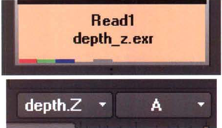
Figure 9.17. (Top) Z channel indicated by gray channel line on a Read node; the line is to the right of the RGB lines. (Bottom) Channel In Alpha and Display Style menus set to display the Z channel. A sample OpenEXR with a Z channel is included as depth_z.exr in the Footage folder on the DVD.
To use a depth pass through a Mask input, follow these steps:
Load the depth render into a Read node. Connect the output of the Read node to the Mask input of a filter node, which will utilize the depth information. For example, connect the Read node to the Mask input of a Blur node.
Open the filter node's properties panel. The Mask check box is automatically selected. If the depth pass is rendered as RGB, change the Mask menu to Rgba.red. Since the depth render is scalar (grayscale), Rgba.red, Rgba.green, and Rgba.blue are identical channels. If the depth pass is rendered as a Z-channel, as might be the case with a Maya IFF or OpenEXR file, change the Mask menu to Depth.Z.
Connect the output of the filter node to a viewer. The effect of the filter node is visible only where the depth values are high. You can invert the result by selecting the filter node's Invert check box.
As an alternative to the Mask input, Nuke provides three Z-buffer nodes. ZSlice, in the Filter menu, is able to isolate a section of an input based on depth channel values. ZBlur, in the Filter menu, is able to blur a section of an input based on depth channel values. ZMerge, in the Merge menu, is designed to merge two depth channels into one depth output.
The ZSlice node requires an input that carries both RGB channels and a Z-depth channel. If the depth pass is written to RGB, you must use the ShuffleCopy node to convert the values into Z channel information. To do so, follow these steps:
Connect the output of the node you want to slice to input 1 of a ShuffleCopy node. Connect the Read node that carries the RGB depth pass to input 2 of the ShuffleCopy node.
Open the ShuffleCopy node's properties panel. Set the various check boxes and menus to match Figure 9.18. Set the In and In2 menus to Rgba. Set the Out menu to Rgba. Set the Out2 menu to Depth.
Attach the output of the ShuffleCopy node to the input of a ZSlice node. Open the ZSlice node's properties panel. Set the Z menu to Depth.Z. Adjust the ZSlice node's Center Of Slice slider to determine what depth channel value will be the center of the depth slice. Adjust the Field Width slider to enlarge or shrink the Z-axis size of the depth slice. Note that the ZSlice node leaves rough, pixilated edges along the slice.

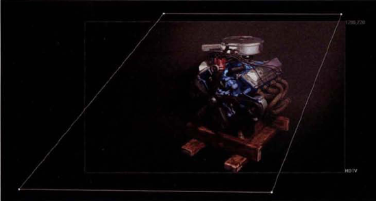
Figure 9.18. (Top Left) Beauty render of engine (Top Center) Engine sliced by ZSlice node (Top Right) Node network (Bottom Left) ShuffleCopy node settings (Bottom Right) ZSlice node settings. A sample Nuke script is included as zslice.nk in the Tutorials folder on the DVD.
The ZBlur node works in a similar fashion to the ZSlice node and also requires an integrated Z channel. Assuming that the Z channel is present, you can follow these steps to apply the node:
Connect the output of the node you want blur to the input of the ZBlur node. Open the ZBlur node's properties panel. Set the Z menu to Depth.Z. Set the Math menu to the depth interpretation that's appropriate. For example, if the Math menu is set to Direct, the value of the depth channel is multiplied by the Size slider to determine the strength of the blur. If the Math menu is set to -Direct, the result is inverted.
To determine the center of the focal plane, you can use the ZBlur node's test function. To do so, select the Focal-Plane Setup check box. Adjust the Focus Plane (C) slider to determine what depth channel value equates to the center of the region of focus. Adjust the Depth-Of-Field slider to enlarge or shrink the Z-axis size of the region of focus. With the Focal-Plane Setup check box selected, the region of focus is rendered in green (see Figure 9.19). The area behind the region of focus is rendered in red. The area between the camera and the region of focus is rendered in blue. Once you've successfully placed the focus region, deselect the Focal-Plane Setup check box. To strengthen the blur, raise the Size slider.
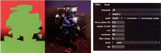
Figure 9.19. (Left) ZBlur output with Focal-Plane Setup check box selected. Green represents area in focus. (Center) Resulting blur on background (Right) ZBlur properties panel. A sample Nuke script is included as zblur.nk in the Tutorials folder on the DVD.
The ZMerge node creates a merge by evaluating the Z channels and alpha channels of the inputs. For example, in Figure 9.20, two parts of a lamp are merged together. The ZMerge Z Channel menu is set to Depth.Z, while the Alpha channel check box is unselected. The lamp's central stack of spheres and remaining base fit together because they carry unique Z channel values. Wherever surfaces are close together, however, the ZMerge node is prone to create intersections. To avoid this, you can adjust the values of a Z channel with a Grade node. In the Figure 9.20 example, a Grade node is added to Read2, which carries a render of the isolated lamps spheres. You can reverse the interpretation of the Z channel, whereby low values are assumed to be in the distance, by selecting the Smaller Z check box. Note that the ZMerge node tends to creates aliased edges.

You can employ the UV channels of a motion vector pass by using the VectorBlur node (in the Filter menu). Here are a few tips to keep in mind:
VectorBlur requires that its input contain RGB and UV channels. If the UV motion vector information is carried by the red and green channels of an RGB file, it will be necessary to transfer the channel information via a Copy or ShuffleCopy node.
For best results, the motion vector pass should be rendered as a floating-point image sequence (such as OpenEXR). Select the Raw Data check box of the Read node that carries the pass.
Ideally, the motion vector pass should be unpremultiplied. If necessary, you can connect the output of the Read node to an Unpremult node.
Nuke expects the motion vector values to represent pixel displacement values in the negative (left/down) and positive (right/up) directions. Since many 3D motion vector renders output normalized motion vector values that run between 0 and 1.0, it may be necessary to adjust the values through the VectorBlur's Add, Multiply, and Offset parameters or by adding an Expression node to the network.
The VectorBlur node offers two forms of motion vector interpretation, which are set by the Method menu. The Backward interpretation is a fast algorithm suited for animation with simple translations. The Forward interpretation plots every pixel's motion path and thus can handle complex translations and rotations.
If the edge of the resulting motion blur is pixilated or otherwise harsh, add a Blur node to the UV channels before feeding them into the VectorBlur node.
As an example, in Figure 9.21, a motion vector pass and beauty pass of a primitive torus are imported through two Read nodes. The motion vector pass encodes the UV directional information in the red and green channels. The magnitude of the displacement is encoded in the blue channel. The motion vector pass is connected to an Unpremult, Blur, and Expression node before reaching a ShuffleCopy node. The Expression node adjusts the UV values in anticipation of their use with a VectorBlur node. The red channel is fed the expression formula (r − 0.5)×(b×500). In this case, r stands for the red channel and b stands for the blue channel. To create a suitably long blur trail, the normalized red channel values must be significantly increased so that they run along a negative and positive scale. The green channel has a similar expression formula: (g − 0.5) × (b × 500). (For more information on expressions, see Chapter 12.) The ShuffleCopy node combines the beauty pass RBG channels with the motion vector pass UV channels. The VectorBlur node takes the combined channels and applies the blur. The VectorBlur's UV Channels menu is set to Forward, while the Offset cell is set to −0.5. The Offset cell determines the start of the virtual shutter. By increasing or decreasing the Offset value, you can push the motion blur forward or backward in time. The Multiply cell, which controls the strength of the blur, is left at a default 1.0. If the Expression node was not present, it would be necessary to increase the Multiply node to a large value, such as 25.

Figure 9.21. (Top Left) Beauty render of moving torus (Top Center) Matching motion vector pass showing red and green channels (Top Right) resulting motion blur (Center Left) Expression node formulas (Center Right) VectorBlur node settings (Bottom) Node network. A sample script is included as motion_vector.nk in the Tutorials folder on the DVD.
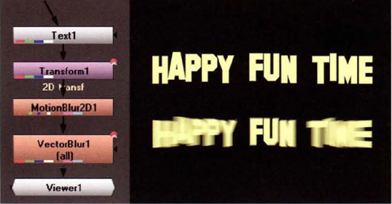
As an alternative approach, you can use the MotionBlur2D node to pull motion vector information from a Transform node. For example, in Figure 9.22, a line of text is scaled and thus gains blur. In this case, a Text node is connected to a Transform node, the Scale parameter of which is animated changing over 30 frames. The output of the Transform node is connected to both inputs of a MotionBlur2D node. One input, which is not labeled, passes the RGB values to the node. The second input, labeled 2D Transf, derives UV channel information from the Transform node. Note that the node icon has violet and cyan channel lines to indicate the presence of UV channels. The output of the MotionBlur2D node is connected to a VectorBlur node, which results in a blur suitable for a change in scale. In this case, the VectorBlur node's UV Channels menu is set to Motion, which is the default motion vector output of the MotionBlur2D node.
In this chapter, you'll have the opportunity to combine render passes from a CG engine as well as extract lighting information from an RGB light pass of a brass horn.
Render passes give the compositor a great deal of flexibility when compositing a shot. The trickiest part of this process, however, is determining the correct layer order and appropriate blending modes.
Create a new project. Choose Composition → New Composition. In the Composition Settings dialog box, change the Preset menu to HDV/HDTV 720 29.97, set Duration to 1, and click OK. Choose File → Project Settings. In the Project Settings dialog box, change the Working Space menu to a color space suitable for your monitor. Since this tutorial involves balancing the contributions of multiple render passes, it's important that the color space settings for the project are appropriate. Although sRGB IEC6 1996-2.1 will work for projects that remain on a PC, the Working Space menu lists all the color profiles available on your system, including those designed for film and video. (See Chapter 2 for more information on color space settings.)
Import the files listed below from the Footage folder on the DVD. If the filename has an asterisk beside it, select the Premultiplied radio button when the Interpret Footage dialog box pops up. If a filename doesn't have an asterisk beside it, you can select the Ignore radio button.
engine_ao.tga*
engine_background.tga
engine_depth.tga
engine_diffuse.tga*
engine_fan_rim.tga
engine_fog.tga
engine_self_shadow.tga*
engine_ref_holdout.tga*
engine_reflect.tga*
engine_rim.tga
engine_shadow.tga*
engine_spec.tga
LMB+drag
engine_background.tgafrom the Project panel to the layer outline of the Timeline panel. LMB+dragengine_shadow.tgaon top ofengine_background.tga. A cast shadow is placed on top of the empty background. Because the shadow pass features a shadow in the alpha channel, the shadow shape is automatically cut out (see Figure 9.23). To reduce the strength of the shadow, you can reduce theengine_shadow.tgalayer's Opacity slider.LMB+drag
engine_diffuse.tgato the top of the layer outline. LMB+dragengine_self_shadow.tgato the top of the layer outline. Change theengine_self_shadow.tgalayer's Opacity to 95%. The self-shadow pass works in the same manner as the cast shadow pass but includes shadows only on the engine. LMB+dragengine_ao.tgato the top of the layer outline. Change theengine_ao.tgalayer's blending mode to Multiply. This multiplies the values within the ambient occlusion render by the diffuse render. Areas of the ambient occlusion pass that are white have no affect on the diffuse render. Areas of the ambient occlusion layer that are gray or black darken the diffuse render (see Figure 9.24). To change the blending mode of a layer, you can select the layer name in the layer outline, RMB+click, and choose Blending Mode → blending mode. You can also click the Toggle Switches/Modes button at the bottom of the Timeline panel to reveal the Mode menus beside each layer.LMB+drag
engine_reflect.tgato the top of the layer outline. The chrome air cleaner and value covers occlude parts of the diffuse render inappropriately. To solve this, LMB+dragengine_ref_holdout.tgato the top of the layer outline. Use Figure 9.25 as a reference. Toggle off the Video layer switch beside theengine_ref_holdput.tgalayer to hide it. Select theengine_reflect.tgalayer and choose Effect → Channel → Set Matte. In the Effect Controls panel, change the Take Matte From Layer Menu to 1.engine_ref_holdout.tga. Select the Invert Matte check box. The reflection layer is properly integrated into the composite (see Figure 9.25). The Set Matte effect borrows the alpha information from theengine_ref_holdout.tgalayer, inverts it, and applies the matte information to theengine_reflect.tgalayer. Set theengine_reflect.tgalayer's Opacity to 90% to dull the reflection. With theengine_reflect.tgalayer selected, choose Effect → Blur & Sharpen → Gaussian Blur. Set the Gaussian Blur effect's Blurriness to 0.5 to reduce the fine noise trapped in the reflection render.LMB+drag
engine_rim.tgato the top of the layer outline. Change theengine_rim.tgalayer's blending mode to Screen. This places a white rim along the engine edges. Reduce theengine_rim.tgalayer's opacity to 15% to make the rim less severe. LMB+dragengine_fan_rim.tgato the top of the layer outline. Change theengine_fan_rim.tgalayer's blending mode to Screen and reduce its opacity to 15%. LMB+dragengine_spec.tgato the top of the layer outline. Change theengine_spec.tgalayer's blending mode to Screen and reduce its opacity to 35%.LMB+drag
engine_fog.tgato the top of the layer outline. Change the engine_fog tga layer's blending mode to Screen. This places a beam of spotlight fog over the engine. Unfortunately, the edge of the fog cone is sharp in the upper-left corner. To soften this, select theengine_fog.tgalayer and draw a mask with the Pen tool to establish new fog cone edges (see Figure 9.26). In theengine_fog.tgalayer's Mask 1 section, change the Mask Feather cells to 200, 200. To reduce the fog intensity, set theengine_fog.tgalayer's opacity to 15%. To prevent the fog from washing out the details of the engine, select theengine_fog.tgalayer and choose Effect → Color Correction → Curves. In the Effect Controls panel, adjust the Curves effect's curve to add additional contrast to the fog. The goal is to keep the engine shadows fairly dark. To soften the fog, select theengine_fog.tgalayer and choose Effect → Blur & Sharpen → Fast Blur. In the Effect Controls panel, set the Fast Blur effect's Blurriness slider to 5.Choose Composition → New Composition. In the Composition Settings dialog box, change the Preset menu to HDV/HDTV 720 29.97 and set Duration to 1. LMB+drag
engine_depth.tgato the Comp 2 tab of the Timeline panel. With the new layer selected, choose Effect → Brightness & Contrast. Set the Contrast slider to 50. This adjusts the RGB depth pass so that it will be useful as a matte for creating artificial depth of field.Choose Composition → New Composition. In the Composition Settings dialog box, change the Preset menu to HDV/HDTV 720 29.97 and set Duration to 1. LMB+drag two copies of Comp 1 from the Project panel to the Comp 3 tab of the Timeline panel. LMB+drag Comp 2 to the top of the Comp 3 layer outline (see Figure 9.27).

Figure 9.26. (Top) Rim, specular, and fog passes are blended with the Screen mode. (Bottom) Mask drawn to soften the edge of the fog pass layer
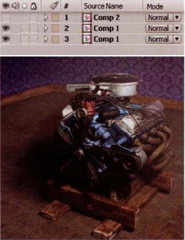
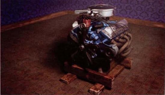
Figure 9.27. (Top) The final Comp 3 layer outline (Bottom) Background blurred with Set Matte and Gaussian Blur effects
Toggle off the Video layer switch beside Comp 2. With the middle Comp 1 layer selected (marked 2 in the layer outline), choose Effect → Channel → Set Matte. In the Effect Controls panel, set Take Matte From Layer to 1. Comp 2. Set the Use Matte For menu to Luminance and select the Invert Matte check box. This uses the luminance information from the Comp 2 layer to supply an alpha matte to the middle Comp 1 layer. With the middle Comp 1 layer selected, choose Effect → Blur & Sharpen → Gaussian Blur. Set the Gaussian Blur effect's blurriness to 5. Because the layer was matted with the Set Matte effect, the layer opacity decreases from the background to the foreground. Therefore, the result of the Gaussian blur appears over the background only when the middle Comp 1 layer is blended with the bottom Comp 1 layer. (To see the blur by itself, temporarily toggle off the Video layer switch beside the bottom Comp 1 layer.)
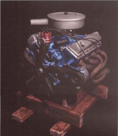
At this stage, the engine remains somewhat washed out. To restore contrast to the composite, select the middle Comp 1 layer and choose Effect → Color Correction → Curves. In the Effect Controls panel, adjust the Curves effect's curve to darken the background (see Figure 9.28). Select the lower Comp 1 layer and choose Effect → Color Correction → Brightness & Contrast. In the Effect Controls panel, set the Contrast slider to 10 to darken the engine's shadows. The tutorial is complete. A sample After Effects project is included as
ae10.aepin the Tutorials folder on the DVD.


Render passes give the compositor a great deal of flexibility when compositing a shot. The trickiest part of this process, however, is determining the correct node order and appropriate Merge node Operation menu settings.
Create a new script. Choose Edit → Project Settings. In the Project Setting properties panel, change the frame range to 1, 1. Change Full Size Format to New. In the New Format dialog box, change the File Size W cell to 1280 and the H cell to 720. Enter HDTV into the Name cell and click OK. Note that the Display_LUT menu of the viewer panel is set to sRGB by default. Since the contributions of multiple render passes must be balanced in this tutorial, it's important that the color space you're working in is appropriate for your monitor. If the tutorial were destined for film or video, for example, a different Display_LUT setting would be necessary. (See Chapter 2 for more information on color space settings.)
Import the files listed below from the Footage folder on the DVD via Read nodes. If the filename has an asterisk beside it, select the Premultiplied check box in the corresponding Read node's properties panel.
engine_ao.tga*
engine_background.tga
engine_depth.tga
engine_diffuse.tga*
engine_fan_rim.tga
engine_fog.tga
engine_self_shadow.tga*
engine_ref_holdout.tga*
engine_reflect.tga*
engine_rim.tga
engine_shadow.tga*
engine_spec.tga
Due to the number of render passes, you will need eight Merge nodes. Create these by RMB+clicking over an empty area of the Node Graph and choosing Merge → Merge. Rename the Merge nodes as follows:
CombineRims
AddSelfShadow
AddRims
AddSpec
AddAO
AddReflect
AddFog
AddFGToBG
Connect the
engine_fan_rim.tgaRead node to input A of CombineRims. Use Figure 9.29 as reference for the final node network. Connect theengine_rim.tgaRead node to input B of CombineRims. This merges the two rim light passes.Connect the
engine_self_shadow.tgaRead node to input A of AddSelfShadow. Connect theengine_diffuse.tgaRead node to input B of AddSelfShadow. This places the self-shadow over the engine. Connect CombineRims to input A of AddRims. Connect AddSelfShadow to input B of AddRims. Set the AddRims node's Operation menu to Screen. This places the rim light over the engine. Set the Mix slider of the AddRims node to 0.2 to reduce the rim intensity.Connect the
engine_spec.tgaRead node to input A of AddSpec. Connect AddRims to input B of AddSpec. This adds specular highlights to the otherwise diffuse engine. Set the AddSpec node's Operation menu to Screen. Set the Mix slider of the AddSpec node to 0.2 to reduce the specular intensity. Connect theengine_ao.tgaRead node to input A of AddAO. Connect AddSpec to input B of AddAO. Set the AddAO node's Operation menu to Multiply. This darkens the surface convolutions of the engine by multiplying the color values by an ambient occlusion pass (see Figure 9.30).Select the
engine_reflect.tgaRead node, RMB+click, and choose Filter → Blur. Set the Blur1 node's Size slider to 1.25. The blur softens fine noise found within the reflection render. Connect the Blur1 node to input A of AddReflect. Connect AddAO to input B of AddReflect. Connect theengine_ref_holdout.tgaRead node to the Mask input of AddReflect. In the AddReflect node's properties panel, select the Invert check box. Theengine_ref_holdout.tgafeatures an alpha matte that defines what does and what does not occlude the chrome valve covers and air cleaner. If theengine_ref_holdout.tgafile is removed, the chrome components will block the spark plug wires, manifold, and distributor inappropriately. Set the AddReflect node's Mix slider to 0.8 to dull the reflection slightly (see Figure 9.31).Connect the
engine_fog.tgaRead node to input A of AddFog. Connect AddReflect to input B of AddFog. Open the AddFog node's properties panel. Change the Operation menu to Screen and set the Mix slider to 0.025. This places light-driven atmospheric fog into the scene. Unfortunately, the edge of the fog cone is sharp. To soften the edge, you can draw a mask. To do so, RMB+click with no nodes selected and choose Draw → Bezier. With the Bezier1 node's properties panel open, Ctrl+Alt+click and draw a mask shape in the viewer to define a new fog edge (see Figure 9.32). To add sharp corners to the mask, RMB+click over each mask vertex and choose Cusp from the menu. Connect the Bezier1 node to the Mask input of the AddFog node. Set the Bezier1 node's Extra Blur slider to 200 and its Falloff slider to 1.0. The edge of the fog becomes soft.Connect the
engine_shadow.tgaRead node to input A of AddFGToBG. Connect theengine_background.tgaRead node to input B of AddFGToBG. Connect AddFog to input A2 of AddFGToBG. (As soon a third connection is made to a Merge node's input, input A is relabeled A1.) The engine and cast shadow is placed over the background (see Figure 9.33).Select the
engine_depth.tgaRead node, RMB+click, and choose Color → Invert. Theengine_depth.tgafile features a Z-buffer depth pass rendered in RGB. However, to be useful as a means to create artificial depth of field and atmosphere, it must be inverted so that the brightness areas are in the distance. With no nodes selected, RMB+click and choose Channel → ShuffleCopy. Connect AddFGToBG to input 1 of ShuffleCopy1. Connect Invert1 to input 2 of ShuffleCopy1. Open the ShuffleCopy1 node's properties panel. Change the In2 menu to Rgba and the Out2 menu to Depth (see Figure 9.34). (For more information on the ShuffleCopy node, see Chapter 4, "Channel Manipulation.") Select the check box in the In2 red column that lines up horizontally with Out2's Z channel. The ShuffleCopy1 node thereby applies the red channel values of the Invert1 node to its Z channel output. At the same time, the RGB values of AddFGToBG are passed through.Select the ShuffleCopy1 node, RMB+click, and choose Filter → ZBlur. Open the ZBlur1 node's properties panel. Set the Z menu to Depth.Z, the Math menu to Direct, Focus Plane to 0.6, Depth-Of-Field to 0.25, Size to 15, and Maximum to 15. A blur is applied to the background without affecting the foreground. To see the focal range more clearly, temporarily select the Focal-Plane Set-Up check box. Green represents the region that remains in focus. Normally, red signifies the area behind the focal region; however, because the depth information is inverted with the Invert node, the blue foreground color is swapped with the red background color.
As a final step, select the ZBlur1 node, RMB+click, and choose Color → Grade. In the Grade1 node's properties panel, set Blackpoint to 0.002 and Gain to 0.8. This returns some of the contrast lost when the fog was added to the composite (see Figure 9.35). The tutorial is complete. A sample Nuke script is included as
nuke10.nkin Tutorials folder on the DVD.


With an RGB light pass, each light is colored a primary color. This gives you the ability to re-light a shot in the composite.
Create a new project. Choose Composition → New Composition. In the Composition Settings dialog box, change the Width cell to 1280 and the Height cell to 960, set Frame Rate to 24, and set Duration to 24. Enter Red Key into the Composition Name cell and click OK. Repeat the process to create three more compositions. Name the second composition Green Fill, the third composition Blue Rim, and the fourth composition Combination.
Import the
horn_beauty.##.tgafootage from the Footage folder on the DVD. The render features a CG horn lit by a key light, a fill light, and a rim light. Import thehorn_rgb.##.tgafootage from the Footage folder on the DVD. The footage features the same CG render; however, each of the three lights is tinted a primary color. The key is red, the fill is green, and the rim is blue. Note that thehorn_rgb.##.tgarender carries shadows while thehorn_beauty.##.tgarender does not.LMB+drag the
horn_beauty.##.tgafootage from the Project panel to the layer outline of the Red Key tab of the Timeline panel. LMB+drag thehorn_rgb.##.tgafootage to the top of the layer outline of the Red Key tab. Toggle off the Video layer switch for thehorn_rgb.##.tgalayer to hide it. Select thehorn_beauty.##.tgalayer and choose Effect → Channel → Set Matte. In the Effect Controls panel, set the Set Matte effect's Take Matte From Layer to 1. Horn_rgb.[1-24].tga. Set Use Matte For to Red Channel. The Set Matte effect converts the light contribution of the CG key, which is colored red, to an alpha matte (see Figure 9.36). Thehorn_beauty.##.tgalayer thereby gains new alpha channel values and thus only reveals the key light illumination.Apply step 3 to the Green Fill and Blue Rim compositions. For the Green Fill composition, set the Set Matte effect's Use Matte For menu to Green Channel. For the Blue Rim composition, set the Set Matte effect's Use Matte For menu to Blue Channel.
Open the Combination composition in the Timeline panel. LMB+drag Red Key, Green Fill, and Blue Rim from the Project panel to the Combination layer outline. The three isolated lights are recombined. You can adjust each light's contribution to the composite by adjusting the corresponding layer's Opacity slider. For example, to reduce, or even turn off, the contribution of the rim light, reduce the Blue Rim layer's Opacity slider. Because the
horn_rgb.##.tgarender contains shadow information for the key and rim light, adjusting the corresponding Opacity sliders causes the shadows to fade in and fade out appropriately.Since each light is isolated as a layer in the Combination composition, you are free to change the color of one or more lights. For example, to change the rim light to green, apply a Hue/Saturation effect (in the Effect → Color Correction menu) to the Blue Rim layer (see Figure 9.37). Set the Master Hue control to 80 and the Master Saturation slider to 80. You can also fine-tune each light's brightness by adjusting the Hue/Saturation effect's Master Lightness slider.
Experiment with the intensity balance of all three lights by adjusting the layers' Opacity sliders. If you've added Hue/Saturation effects, experiment with different color settings. Once you're satisfied with the colors and balance, the tutorial is complete. A sample After Effects script is included as
ae11.aepin the Tutorials folder on the DVD.

With an RGB light pass, each light is colored a primary color. This gives you the ability to re-light a shot in the composite.
Create a new script. Choose Edit → Project Settings. In the Project Setting properties panel, change Frame Range to 1, 24. Change Full Size Format to New. In the New Format dialog box, change the File Size W cell to 1280 and the H cell to 960. Enter 1280 980 into the Name cell and click OK. In the Node Graph, RMB+click and choose Image → Read. In the Read1 node's properties panel, browse for the
horn_beauty.##.tgafootage in the Footage folder on the DVD. Connect a viewer to the Read1 node. The render features a CG horn lit by a key light, a fill light, and a rim light.With no nodes selected, RMB+click and choose Image → Read. In the Read2 node's properties panel, browse for the
horn_rgb.##.tgafootage in the Footage folder on the DVD. The footage features the same CG render; however, each of the three lights is tinted a primary color. The key is red, the fill is green, and the rim is blue. Note that thehorn_rgb.##.tgarender carries shadows while thehorn_beauty.##.tgarender does not.With no nodes selected, create three Copy nodes (Channel → Copy) and three Premult nodes (Merge → Premult). Using Figure 9.38 as reference, create these connections:
Connect Read1 to input B of the Copy1, Copy2, and Copy3 nodes.
Connect Read2 to input A of the Copy1, Copy2, and Copy3 nodes.
Connect Copy1 to Premult1.
Connect Copy2 to Premult2.
Connect Copy3 to Premult3.
Open the properties panel for Copy1. Change the Copy Channel menu to Rgb.red. Open the properties panel for Copy2. Change the Copy Channel menu to Rgb.green. Open the properties panel for Copy3. Change the Copy Channel menu to Rgb.blue.
This series of steps converts each CG light's illumination into an alpha matte. Because each light is colored a primary color, it can be isolated by a Copy node. For example, the red key light has a strong presence in the red channel of the
horn_rgb.##.tgarender. The Copy1 node therefore converts the red channel to an alpha channel. The RGB colors of thehorn_beauty.##.tgarender are passed through by the Copy nodes unharmed.Create three Merge nodes (Merge → Merge). Create these connections and adjustments:
Connect Premult1 to input A of Merge1.
Connect Merge1 to input B of Merge2.
Connect Premult2 to input A of Merge2.
Connect Merge2 to input B of Merge3.
Connect Premult3 to input A of Merge3.
By connecting the Merge nodes in this fashion, you can balance each light's contribution in the composite by adjusting the Merge nodes' Mix sliders. For example, in reduce, or even turn off, the contribution of the rim light, reduce the Merge3 Mix slider (see Figure 9.39). Because the
horn_rgb.##.tgarender contains shadow information for the key and rim light, adjusting the corresponding Mix sliders causes the shadows to fade in and fade out appropriately.
Figure 9.39. (Top Left) Initial composite with all three Merge nodes' Mix sliders set to 1.0. (Top Right) The rim light and fill light are disabled by setting the Merge2 and Merge3 nodes' Mix sliders to 0. Note the appearance of the key shadow. (Bottom Left) The rim light is tinted green with a HueShift node. (Bottom Right) All three lights are tinted by HueShift nodes.
Since each light is isolated by the node network, you are free to change the color of one or more lights. For example, to change the rim light to green, insert a HueShift node between the Premult3 node and the Merge3 node. Set the HueShift node's Hue Rotation slider to −80. If you want to adjust the colors of all three lights, insert a HueShift node after each Premult node. You can also fine-tune each light's brightness by adjusting the HueShift nodes' Brightness sliders.
Experiment with the intensity balance of all three lights by adjusting the Merge nodes' Mix sliders. If you've added HueShift nodes, experiment with different color settings. Once you're satisfied with the colors and balance, the tutorial is complete. A sample Nuke script is included as
nuke11.nkin the Tutorials folder on the DVD.

Dan Rice's first major in college was biotechnology. Recognizing the creative potential in computer graphics, he switched studies and enrolled at the Art Institute of Pittsburgh. His first job at Interactive Media allowed him to combine graphic design with 3D artwork. In 2002, Dan joined Blur and has since worked his way to the positions of art director and CG supervisor. He specializes in look development and oversees game cinematics, commercials, and short films that involve a "more cartoony" style. His involvement with "Gopher Broke" helped lead the short to an Oscar nomination in 2004.
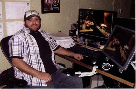
Dan Rice at his workstation. All the animators share a single open workspace.
Blur Studio was founded in 1995 by Tim Miller and David Stinnett. It provides visual effects and animation for feature films, ride films, commercials, game cinematics, and broadcast design. The studio has also produced highly respected animated shorts, including "In the Rough" and "Gentlemen's Duel."
(Blur currently uses After Effects and Fusion for compositing. The studio keeps two dozen compositors on staff, although many compositors model, texture, and light.)
LL: Which game cinematics have you worked on?
DR: The cartoonier ones. For example, Fable...Sonic the Hedgehog....
LL: Are there differences between compositing something that's cartoony as opposed to something that's supposed to look real?
DR: I come from a graphic design background, so I'm really schooled in color design and color theory.... From the art direction standpoint, I think we go through a heftier look-development phase.... We're coming up with art direction, color scripts, moods for the piece—we're establishing all that stuff ourselves as artists.... What I like to do at the beginning of my projects is to have a look-development time, and so I'll explore the look-development in terms of rendering and lighting. I'll talk to the concept artists and try to work out an aesthetic—even before we get into CG.... A good analogy would be the [Pixar] art books—our CG supervisors here are more involved in the [concept art] stage, as opposed to other studios where it's preproduction [where] all the preproduction art is created by 2D artists and then it's handed off to the CG team....
LL: How important is color theory to an animator?
DR: If you want to be a lighter or compositor, having an eye that is color sensitive is extremely important. That's what we look for. It's all about the color aesthetic.
LL: As a supervisor, when you composite a shot to develop the look of a sequence, how do you treat the rendering passes?

The Blur facility in Venice, California
DR: My work process here is to break out my passes to give me the most control in my compositing package.... So, I'll use a diffuse color pass, an ambient skylight pass that has no shadows, an ambient occlusion pass, and then each and every single [3D] light as a separate pass—and [finally] a reflection pass, and Z-depth.... I combine those together [in the comp] to define the look. [The problem is], I don't want to give all that control [back to the lighter].... What we'll [do instead] is collapse all that back down in 3D to match the look [gained in the comp].... [We used] to give the lighters a lot of passes and they could make it work. Now, we're getting away from that. We're going toward the direction where the senior people here—the supervisors—can establish the look [by using all the passes], but then simplify the look for the [lighter] so that they can focus on lighting.... [The passes require a great deal of] rendering, management of assets....
