
Although rendering is the final step of a Maya 3D project, it is often given improper attention. The correct choice of aspect ratios, pixel ratios, frame rates, focal lengths, and film backs at the earliest stage of animation can ensure that the project progresses smoothly. At the same time, careful selection of anti-aliasing, image format, resolution size, depth of field, and motion blur settings will guarantee a successful render. Time-saving techniques, including scene cleanup and command-line rendering, will help you finish projects in a more efficient manner.
Chapter Contents
Selecting aspect ratios and frame rates
Choosing film backs and focal lengths
Recommended render settings
Command-line rendering
Preparing scene files for rendering
Selecting image formats and resolutions
Creating efficient depth of field and motion blur
Aspect ratios, frame rates, and film backs are important elements of any animation project and should therefore be selected early in the production process. Although you can change the aspect ratio at any time, such a change can lead to poor compositions. Selecting a different film back midway through a project can also lead to drastic composition changes and interfere with live-action plate matching. Switching frame rates can lead to improperly timed motion and broken lip sync. Camera focal lengths, although less critical than aspect ratios, frame rates, and film backs, should nonetheless be selected early in the animation process.
Simply put, an aspect ratio of an image is its displayed width divided by its displayed height. Aspect ratios are commonly represented as x:y (for example, 4:3) or x (for example, 1.33), in which x is the width and y is the height. A list of popular aspect ratios, their origins, and representative image resolutions follow (see Figure 10.1).

- 16:9 (1.78)
Standard widescreen video and the aspect ratio of HDTV. Many digital video cameras offer 16:9 as a recording option. In addition, 16:9 is a popular ratio for animations intended for transfer to 35 mm motion picture film. (In this case, the film is projected with a 1.85 mask.) 16:9 ratio projects require letterboxing when played on 4:3 standard definition televisions. The HDTV video standard uses two resolutions—1280 × 720 and 1920 × 1080. Four variations of these two resolutions exist—720i, 720p, 1080i, and 1080p. The i in 720i and 1080i HDTV signifies interlaced frames. The p in 720p and 1080p HDTV signifies progressive frames. Progressive frames are whole frames that have not been interlaced.
Note
In the United States, analog television broadcasts will cease as of February 2009. From that point forward, the broadcast standard will be digital television (DTV). Although HDTV has been embraced by many broadcasters, it is simply one format available to DTV. For example, enhanced digital television (EDTV) is a second variation of DTV that runs at 480p or 576p and can be 16:9 or 4:3.
- 4:3 (1.33)
The standard definition television (SDTV) aspect ratio, whose roots can be traced to silent 35 mm motion pictures created by Thomas Edison. NTSC SDTV broadcasts at a resolution of 480 visible lines. (Additional lines contain data such as sync and captioning.) D1, the first professional digital video format, has a NTSC resolution of 720 × 486 with nonsquare pixels. (See the section "Switching between Square and Nonsquare Pixels" later in this chapter.) The square-pixel version of D1 is 720 × 540. DV, a digital variation now in common usage, has a NTSC resolution of 720 × 480 with nonsquare pixels. Digital video editing programs such as Final Cut Pro offer 720 × 480 as an editing format. A common 3D render size, 640 × 480, is a square-pixel variation of the NTSC format.
Note
The NTSC video standard is used throughout North America and parts of South America. PAL, the video standard in Europe and parts of Asia, Africa, and South America, runs at 720 × 576 for SDTV. SECAM, the video standard used in France, Eastern Europe, Russia, and parts of Africa, runs at the same resolution as PAL.
- 1.66
A masked variation of the 1.37 Academy motion picture format originally developed by Paramount Studios in 1953. A mask is an aperture plate placed behind a projector lens with a cutout "window" that allows only a portion of the film image to reach the screen. 1.66 has since become the standard 35 mm widescreen aspect ratio in many parts of Europe. The 1.37 Academy format was standardized by the American motion picture industry and was used consistently between 1932 and 1953.
- 1.85
Standard theatrical widescreen in the United States and United Kingdom. Much like 1.66, 1.85 was developed as a method to mask 1.37 in the early 1950s. The SDTV and HDTV broadcast of 1.85 motion pictures requires either letterboxing or cropping through electronic pan-and-scan techniques. The 1.85 aspect ratio was used on Surf's Up (2007) and Shrek the Third (2007). The render resolution of feature animation varies between studio and project but generally falls between 2K (2,048 vertical lines) and 4K (4,096 vertical lines).
- 2.35
The aspect ratio of Cinemascope that was developed by 20th Century Fox in the early 1950s. Cinemascope is an anamorphic motion picture format that requires special camera and projector lenses to squeeze and restretch the image for proper viewing. If the anamorphic projector lens is missing, the image will appear excessively tall and skinny. The Incredibles (2004) made use of the 2.35 format.
The NTSC D1 and DV video standards require nonsquare pixels. NTSC D1 and DV nonsquare pixels carry a pixel aspect ratio of 10:11, wherein the height is greater than the width. (10:11 is often expressed as a rounded-off 0.9.) Nonsquare pixels are a legacy requirement of 4:3 SDTV television technology. (The electronic design of a 4:3 SDTV television allows the image to appear normal.) By comparison, computer monitors and HDTV televisions use square pixels. Thus, when a D1 or DV image is displayed on a computer monitor, it appears vertically squished. Editing programs such as Final Cut Pro and Adobe Premiere avoid this problem by offering Show As Square Pixels options.
Note
Each video standard carries its own unique pixel aspect ratio (PAR). For example, PAL D1 and DV have a PAR of 1.066:1 (often expressed as 1.07). 16:9 NTSC D1 and DV have a PAR of 1.2121:1 (often expressed as 1.2). Compositing programs carry the most common pixel aspect ratios as presets.
Note
HDV, a popular high-definition video format, uses the 16:9 aspect ratio. HDV supports 720p and 1080i resolutions. When recording 720p, HDV utilizes a PAR of 1:1. When recording 1080i, HDV uses a resolution of 1440 × 1080 with a PAR of 1.33:1. HDCam, a high-definition variant of Digital Betacam, effectively operates at 1440 × 1080 with a 1.33:1 PAR.
You can set a nonsquare pixel aspect ratio in Maya by changing the Pixel Aspect Ratio attribute in the Render Settings window. For instance, you can set the value to 0.9 for NTSC. However, in order to maximize render quality, it is generally better to render square pixels and "squish" the image in the composite (see Figure 10.2). Thus, when preparing for NTSC DV in Adobe After Effects, a square-pixel 720 × 540 render can be converted to a nonsquare 720 × 480 composite by scaling the image by 90 percent in the X and 88.9 percent in the Y. The size reduction will also serve as an additional form of anti-aliasing. When preparing for NTSC D1, a square-pixel 720 × 540 render can be converted to a 720 × 486 nonsquare composite resolution by scaling by 90 percent in the X and Y.
In Maya, a camera's virtual optical properties are defined in the Film Back section of the camera's Attribute Editor tab (see Figure 10.3). The most important attribute in this section is Film Gate. With a real-world motion picture camera, a film gate is a plate with a rectangular opening that sits behind the lens and in front of the film stock. The gate controls the exposure of the film by allowing only one frame at a time to be struck by light. Commonly used cameras have distinct lens and film gate setups with specific physical properties. These properties cause light to strike the film in a distinct way. The Film Gate attribute's drop-down menu (see Figure 10.3) provides a selection of common motion picture cameras. When one of these camera presets is selected, the Camera Aperture, Film Aspect Ratio, and Lens Squeeze Ratio attributes automatically update. A description of these attributes follows.
- Camera Aperture
A "dummy" attribute that drives Horizontal Film Aperture and Vertical Film Aperture, each of which respectively sets the specific width and height of the virtual film gate (measured in world space inches).
Note
Film back refers to the plate that holds the film against the film gate. With 3D animation software, the term has come to represent the general qualities of the film gate. In contrast, a real-world camera aperture is the articulated diaphragm that opens or closes to control the amount of light striking the film.
- Film Aspect Ratio
Sets the width-to-height ratio of Camera Aperture. As you change the value, the Horizontal Film Aperture field automatically updates.
- Lens Squeeze Ratio
Sets the amount of horizontal squeeze created by a lens. Cinemascope anamorphic lenses require a Lens Squeeze Ratio value of 2. Most lenses do not require a special Lens Squeeze Ratio value and can be left at 1.
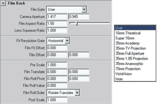
Figure 10.3. (Left) The Film Back section of a camera's Attribute Editor tab; (right) Film Gate presets
If an animation represents an abstract, fanciful, or imaginary scene, you can leave the Film Gate attribute set to the default User. For exaggerated camera effects, you can also enter custom numbers into any of the attributes in the Film Back section. However, if an animation is intended to replicate or fit into preexisting live-action motion picture footage, the Film Gate and associated attributes should be carefully selected.
Note
Video cameras do not have traditional film gates. Their light-gathering CCD or CMOS chips, however, serve the same basic function. When matching a video camera in Maya, you can derive approximate values for Horizontal Camera Aperture and Vertical Camera Aperture. For example, a Canon XL2 camera uses 1/3" chips with 4:3 aspect ratios. A standard 1/3" chip has a width of 4.8 mm and a height of 3.6 mm—or 0.19 × 0.14". (When a chip is labeled 1/3", it is not an indication of its true width, but a reference to standard designations given to television tubes in the 1950s.) The Canon XL2, like most video cameras, does not utilize the entire chip area, but uses a target area appropriate to the shooting mode. Thus, if the camera is shooting DV at 720 × 480, the actual chip area used is roughly 0.14 × 0.09". Specifications for such calculations are often available from chip and video camera manufacturers.
As for choosing an appropriate Focal Length value for a video camera, professional-grade lenses generally have the appropriate information marked on the lens housing.
As you choose an aspect ratio and a film back for an animation project, it is recommended that you use the camera's various gates. Choosing View > Camera Settings > Resolution Gate through the camera workspace view menu displays the Resolution Gate frame in the perspective view. The Resolution Gate represents the maximum render area (see Figure 10.4). The renderer ignores anything outside the Resolution Gate. For extra security, you can toggle on Safe Action and Safe Title gates by choosing View > Camera Settings > Safe Action and View > Camera Settings > Safe Title. Since the average television set (whether SDTV or HDTV) cuts off a portion of the frame between the Resolution Gate and Safe Action gate, keep critical animation within the Safe Action gate. Keep critical text and titles within the Safe Title gate.
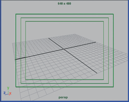
Figure 10.4. The Resolution Gate with Safe Action (middle box) and Safe Title (inner box) toggled on
The Resolution Gate aspect ratio, determined by the Device Aspect Ratio attribute of the Render Settings window, may be different from the Film Aspect Ratio. (See the section "Mastering the Render Settings Window" later in this chapter for more information on Device Aspect Ratio.) Hence, it's recommended that the Fit Resolution Gate attribute, in the Film Back section of the camera's attribute Editor tab, be adjusted. If Fit Resolution Gate is set to Fill, the Film Gate is scaled so that it covers the entire Resolution Gate. Depending on the render resolution, a portion of the Film Gate may be lost outside the Resolution Gate. To see the results of Fit Resolution Gate, you can display the Resolution Gate and Film Gate simultaneously by checking Display Resolution and Display Film Gate in the Display Options section of the camera's Attribute Editor tab. If Fit Resolution Gate is set to Horizontal or Vertical, the Film Gate is scaled in one direction so that it matches the Resolution Gate's dimension in that direction; any gap that appears in the opposite direction will render as normal unless Ignore Film Gate is unchecked in the Render Options section of the Maya Software tab in the Render Settings window. If Fit Resolution Gate is set to Overscan, the Film Gate is fit within the Resolution Gate so that no part is left unrendered; a gap between the gates may appear at the top and bottom. The only way to avoid gaps is to provide the Device Aspect Ratio and Film Aspect Ratio with identical values.
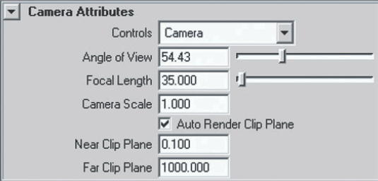
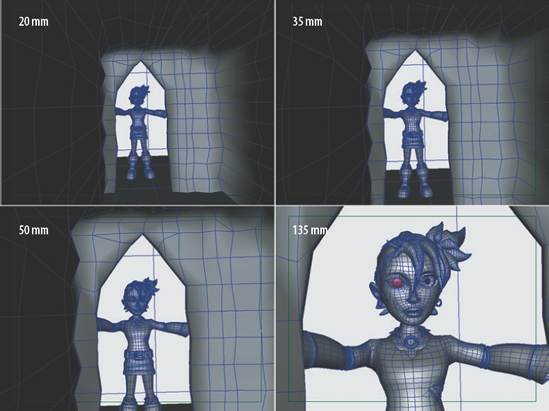
Focal length is the distance from the optical center of a lens to its focal point (the point at which the light rays are focused). Once specific shots are determined within an animation project, it's wise to select specific focal lengths. Motion picture and television productions regularly change focal lengths (and even the entire lens) from shot to shot. Different focal lengths can have a significant impact on camera placement, composition, and object distortion. (See Chapter 7 for a demonstration.) Focal length is controlled in the Camera Attributes section of the camera's Attribute Editor tab, which includes Angle Of View, Focal Length, and Camera Scale attributes (see Figure 10.5).
- Angle Of View
A measurement of the angular extent visible through the camera. If this attribute is changed, the Focal Length attribute automatically updates. Since the formula used by Angle Of View is very obscure, it is much more convenient to set the Focal Length attribute.
- Focal Length
Sets the focal length of a camera lens as measured in millimeters. Common real-world focal lengths include 20 mm, 35 mm, 50 mm, and 135 mm (see Figure 10.6).
Note
Scientific studies have estimated that the human eye has a focal length ranging from 22 mm to 24 mm, although numbers as high as 50 mm are popularly quoted. If you choose a 22 mm lens in Maya, the camera will not necessarily match a human angle of view since there is no "human eye" film gate available.
A proper frame rate, or frames per second (fps), is critical for smooth animation. To set the rate, choose Window > Setting/Preferences > Preferences, switch to the Settings section, and choose an option from the Time attribute drop-down menu (see Figure 10.7). Maya provides the most common frame rates, including 24, 25, and 30.
- 24 fps
The standard frame rate of motion picture film.
- 25 fps
The standard frame rate of PAL and SECAM video.
- 30 fps
The standard frame rate of NTSC video. 30 fps is a simplification of the more technically accurate 29.97 fps.
Note
To accurately gauge an animation when using the Timeline's playback controls, you must switch the Playback Speed attribute to Real-Time. You can find Playback Speed in the Timeline section of the Preferences window (choose Window > Setting/Preferences > Preferences).

Standard television transmission requires the use of interlaced fields. Thus, in reality, PAL runs at 50 interlaced fps and NTSC runs at 60 interlaced fps (or, more accurately, 59.94 interlaced fps). The interlacing process splits any given frame into interlaced upper and lower fields, with one field drawn first and the other field drawn second. Whether the upper field or lower field is drawn first is dependent on the video's field dominance. This varies with video format. You can render interlaced frames in Maya by choosing PAL Field or NTSC Field from the Time drop-down menu in the Settings section of the Preferences window. Compositing programs, such as Adobe After Effects, can also convert noninterlaced frames to interlaced frames at the point of render.
One of the most difficult aspects of rendering is the conversion of one frame rate to another. The conversion of motion picture footage to NTSC video, for instance, requires the 3:2 pulldown process. A 3:2 pulldown converts four film frames into ten interlaced video frames. Two of the frames are repeated three times and two of the frames are repeated twice. 3:2 pulldowns are normally created with telecine machines but can be created with compositing programs such as Adobe After Effects or Autodesk Combustion. Compositing plug-ins, such as RE:Vision Effects Twixtor, offer additional techniques for interpolating and smoothing out frame rate conversions.
To avoid potential fps conversion difficulties, determine the primary presentation format of an animation project early on. If the work is destined for 35 mm transfer and a theatrical release or the film festival circuit, 24 fps would make the most sense. If an animation is created for a television commercial in the United States, 30 fps is necessary. If an animation needs to go to multiple outlets at multiple points around the globe, conversion artifacts should be expected. Even though many postproduction houses can electronically or digitally convert between frame rates, the result is never as smooth as the original. For instance, converting from PAL to NTSC will leave a "judder" in the animation where a slight hesitation appears every few frames.
The majority of Render Settings window attributes are intuitive and easy to use. However, several of them are worth a closer look. The attributes are divided into Common and renderer-specific tabs. The Common tab includes Frame Padding, Alpha Channel (Mask), Depth Channel (Z Depth), Resolution, Resolution Units, Device Aspect Ratio, and Pixel Aspect Ratio attributes (see Figure 10.8).
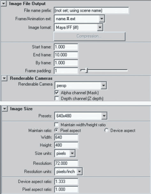
Figure 10.8. The Image File Output and Image Size sections of the Common tab in the Render Settings window
- Frame Padding
Ensures that each filename carries the same number of numeric placeholders. Many compositing programs, such as Adobe After Effects, expect specific frame numbering conventions. For example, After Effects will incorrectly order the following files:
Test.1.jpg
Test.5.jpg
Test.10.jpg
Test.100.jpg
However, if the Frame Padding attribute is set to 3, the images will be named in the universally understood manner:
Test.001.jpg
Test.005.jpg
Test.010.jpg
Test.100.jpg
- Alpha Channel (Mask)
Toggles on the alpha channel for select image formats (Maya IFF, TIFF, Targa, RLA, and SGI). Alpha represents the opacity of objects in a scene. Alpha is stored as a scalar (grayscale) value in the fourth channel (the A in RGBA). In Maya, white indicates opaque objects and black indicates empty space. You can view the alpha channel in the Render View window by clicking the Display Alpha Channel button. Common compositing programs easily read the Maya alpha channel.
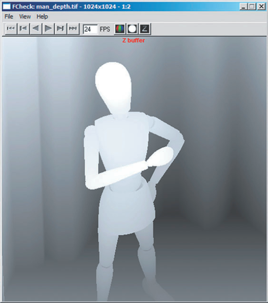
- Depth Channel (Z Depth)
Toggles on the depth channel for select image formats (Maya IFF and RLA). With TIFF, Targa, and SGI images, the attribute causes the depth channel to be written out as a separate file with a _depth suffix. Depth channels represent the distance between the camera and objects in the scene. Depth channels (sometimes referred to as Z-depth buffers) are employed by compositing programs to determine object occlusion. For example, a depth channel might be used to properly place 2D fog "into" a rendered 3D scene or to create a depth-of-field effect as part of the compositing process. In another variation, Maya depth map shadows are depth channel maps from the view of the light (see Chapter 3). You can view the depth channel of an image file by choosing File > View Image, browsing for the file, and clicking the Z Buffer button in the FCheck window (see Figure 10.9). Like alpha channels, depth channels are scalar.
- Resolution and Resolution Units
For video and film, the image size is determined solely by the Width and Height attributes. For projects destined for print, however, the Resolution attribute is added to determine pixels per inch. For example, many print jobs require 300 pixels per inch. You can thus set the Resolution attribute to 300 and the Resolution Units attribute to Pixels/Inch.
- Device Aspect Ratio
Defines the aspect ratio of rendered images based on the following formula:
Device Aspect Ratio = Image Aspect Ratio × Pixel Aspect Ratio
The image aspect ratio is determined by dividing the Width attribute by the Height attribute. For example, if Width is set to 720, Height is set to 480, and Pixel Aspect Ratio is set to 0.9, the Device Aspect Ratio is set automatically to 1.35. Device refers to output device, such a television or computer monitor. (See the section "Deciphering Aspect Ratios" earlier in this chapter.)
- Pixel Aspect Ratio
Defines the aspect ratio of individual pixels. If set to 1, the pixels are square and do not affect the Device Aspect Ratio calculation. If set to 0.9, the pixels are nonsquare NTSC. (See the section "Switching between Square and Nonsquare Pixels" earlier in this chapter.)
Render-specific attributes reside in the Maya Software, Maya Hardware, and Maya Vector tabs. (See Chapter 11 for a discussion of mental ray attributes.)
The Maya Software renderer is a general-purpose renderer that is suitable for most projects. Critical attributes include Edge Anti-Aliasing, Shading, and Max Shading. Important sections include Multi-Pixel Filtering and Contrast Threshold (see Figure 10.10).
- Edge Anti-Aliasing
Anti-aliasing is an inescapable necessity of 3D and other computer graphics. Due to the physical limitations of computer monitors and televisions (which possess a limited number of display pixels), normally smooth edges become "jaggy" or "stair-stepped." Maya's anti-aliasing process uses a subpixel sampling technique that computes multiple sample points within a single pixel and assigns the averaged sample values to that pixel. Although Maya offers various anti-aliasing presets, such as Low Quality or High Quality, you can tailor the anti-aliasing by entering values into the Shading and Max Shading attribute fields.
- Shading
Sets the minimum number of subpixel samples taken within a pixel during the anti-aliasing process. If set to 1, each pixel is sampled one time. If set to 4, each pixel is sampled four times. The number of subpixel samples is not permitted to exceed the Max Shading value.
- Max Shading
Sets the maximum number of subpixel samples taken within a pixel during the adaptive shading pass of the anti-aliasing process. This is in effect only when the Edge Anti-Aliasing attribute is set to Highest Quality. Whether or not the Max Shading value is applied is dependent on Contrast Threshold attribute, which controls the adaptive shading pass.
- Contrast Threshold
This section controls the adaptive shading pass of the anti-aliasing process. The Edge Anti-Aliasing attribute must be set to Highest Quality for the Contrast Threshold section to function. Contrast Threshold tests for pixels whose contrast with neighboring pixels exceeds the Red, Green, or Blue attribute threshold values. For these pixels, additional subpixel sampling is undertaken. In this case, Max Shading sets the maximum number of permitted samples.
- Multi-Pixel Filtering
Multi-pixel filtering is designed to blend neighboring pixels into a coherent mass. Such filtering helps to prevent common aliasing artifacts. In particular, multi-pixel filtering can improve renders destined for video. The interlaced nature of television is harsh and tends to exaggerate aliasing problems. A slightly soft render, thanks to the multi-pixel filtering process, can look better on video than a nonfiltered render. However, a similar multi-pixel filter applied to a render destined for motion picture film or a web-based movie can prove inferior. In such a case, uncheck Use Multi Pixel Filter. Even if the render is intended for video, it might be wise to reduce the Pixel Filter Width X and Pixel Filter Width Y attributes until the render can be properly tested.
If Use Multi Pixel Filter is checked, you can select five filter styles from the Pixel Filter Type drop-down menu: Box Filter, Triangle Filter, Gaussian Filter, Quadratic B-Spline Filter, and Plug-in Filter. Of these, Box Filter produces the softest result, while Gaussian Filter produces the sharpest. Triangle Filter, which is the default, produces a moderate degree of softness. Quadratic B-Spline is a legacy filter from the first version of Maya. Plug-in Filter allows you to write a custom filter in Maya's
.mllplug-in language. The Use Multi Pixel Filter attribute is automatically checked when the Quality attribute (in the Anti-Aliasing Quality section) is set to Production Quality, Contrast Sensitive Production, or 3D Motion Blur Production.

Note
You can adjust and refine the render quality of NURBS surfaces outside the Render Settings window. NURBS tessellation attributes are accessible through the surface's Attribute Editor tab. For a detailed discussion of these attributes, see section 10.1 of the Additional_Techniques.pdf file on the CD.
The Maya Hardware renderer provides a quick method of rendering tests and other projects that do not require a high degree of refinement (see Figure 10.11). The Hardware renderer uses the built-in capabilities of the system graphics card.
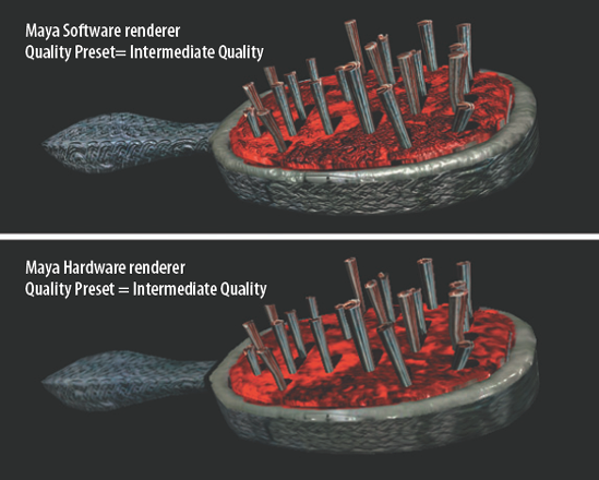
Figure 10.11. (Top) A model rendered with Maya Software. (Bottom) The same model rendered with Maya Hardware via an entry-level graphics card.
The easiest way to set the quality of the Hardware renderer is to use one of the four options of the Presets attribute (Preview Quality, Intermediate Quality, Production Quality, and Production Quality With Transparency). Nevertheless, many of the corresponding attributes are unique and are worth a closer look (see Figure 10.12).

- Number Of Samples
Defines the number of subpixel samples taken per pixel during the anti-aliasing process.
- Color Resolution and Bump Resolution
Control the size of the 2D image that the renderer must bake (pre-render) if it encounters a color or bump shading network that is too complex to evaluate directly.
- Culling
Controls whether single-sided and double-sided qualities are evaluated per object or are universally overridden. A Small Object Culling Threshold attribute is also provided, allowing opaque objects smaller than the threshold to be ignored by the renderer. (The threshold is a percentage of the render resolution.)
- Hardware Geometry Cache
When checked, allows the renderer to cache geometry to the unused portion of the on-board memory of the graphics card.
- Motion Blur
When checked, enables hardware motion blurring. The Motion Blur By Frame attribute sets the time range that the renderer uses to evaluate a moving object's before and after position. The Number Of Exposures attribute determines the number of discrete positions within the time frame that the renderer uses to refine the blur. The higher the exposure number, the smoother and more accurate the result. (For additional information on motion blur, see the section "Applying Motion Blur" later in this chapter.)
Note
In general, the Maya Hardware renderer is superior to Maya's Hardware Render Buffer. The Maya Hardware renderer can render hardware-rendered particles, texture maps, bump maps, displacement maps, and complex lighting. This ability is dependent, however, on the compatibility of the installed graphics card. For a list of graphics cards recommended for Maya, visit www.autodesk.com.
The Maya Vector renderer can create stylized cartoon and wireframe renders (see Figure 10.13). Although the majority of options are straightforward, a few warrant a more detailed description.
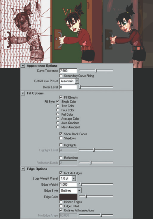
Figure 10.13. Top, Left to Right) Maya Vector renderer with Single Color and Entire Mesh, Vector with Single Color and Outlines, Vector with Four Color. (Bottom) The Maya Vector tab in the Render Settings window.
- Curve Tolerance
Determines the smoothness of a NURBS or subdivision surface edge. A value of 0 will leave the edge faceted (as if the surface was converted to a polygon). The maximum value of 15 will smooth the surface to such an extent that it becomes slightly distorted. The Curve Tolerance attribute has no effect on polygon surfaces.
- Detail Level and Detail Level Preset
Detail Level controls the accuracy of the Vector renderer. A high value improves the quality but slows the render significantly. Detail Level Preset, if set to Automatic, overrides the Detail Level attribute. You can also set the Detail Level Preset to standard quality settings, which include Low, Medium, and High. If Detail Level Preset is set to Low, small polygons are combined with adjacent polygons, thus negating any fine detail.
- Fill Style
Controls the solid color that appears on the surface of rendered objects. The Single Color radio button, when clicked, creates a solid color based on the surface material. The Average Color radio button also creates a single color based on the material, but includes shading based on the scene lighting. The Two Color and Four Color radio buttons add additional solid colors based on the material color and scene lighting. The Full Color radio button tints each individual polygon face with a solid color based on the surface material and scene lighting. The Mesh Gradient and Area Gradient radio buttons apply color gradients based on material color and scene lighting. Mesh Gradient and Area Gradient are supported by the SWF format. (See the section "Differentiating Image Formats" later in this chapter.) In addition, you can check on and off Shadows, Highlights, and Reflections in this section.
- Include Edges
When checked, creates edge lines. The Edge Weight Preset attribute controls the thickness of the line. If the Edge Style attribute is set to Outlines, a line will be created at the outer edge of each surface. If the Edge Style attribute is set to Entire Mesh, a line is drawn along each and every polygon edge. In this case, all polygon faces are rendered as triangles. In addition, NURBS surfaces will have lines drawn at polygon edges derived from the tessellation process.
You can launch a batch render with the Maya Software or mental ray renderer from the Microsoft Windows Command Prompt window, the Macintosh OS X's Terminal window, or the shell window of a Linux system. It is not necessary to run the Maya interface. Hence, this method of rendering can be efficient. To achieve this, a Maya .mb or .ma file need only be saved in advance. At that point, follow these steps:
Launch the Command Prompt window (in Windows XP, choose All Programs > Accessories > Command Prompt), the Terminal window (found in the Macintosh's OS X Utilities folder), or appropriate Linux shell window.
Switch to the directory in which the appropriate
.mbor.mafile resides. For example, in Windows the command might becd c:3dmayaprojects
Launch the software renderer by entering
render
file_name
The Maya Software renderer proceeds using the settings contained within the Render Settings window when the file was saved. You can interrupt the renderer at any time by pressing Ctrl+C in the Command Prompt or Terminal window. You can simultaneously launch multiple renders in separate Command Prompt, Terminal, or shell windows; the renders will evenly divide the available CPU cycles.
If you prefer to render with mental ray, you must enter this:
render -r mr file_nameThe -r or -renderer flag specifies the renderer used. You can override the file's render settings by using various flags. For instance, you can force the renderer to render frames 5 to 10 with the following line:
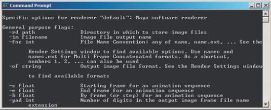
render file_name -s 5 -e 10To display the lengthy list of render flags, open Help with the following line (see Figure 10.14):
render -h
Rendering is the final step of the animation process, yet it requires the same attention to detail as any other aspect of 3D to be successful. Creating clean scene files and establishing appropriate paths to bitmaps are important steps.
The speed of any given Maya render depends on the quality of the scene file. If a scene file contains unnecessary construction history, broken nodes, and unneeded geometry, the render will suffer. A quick solution to this problem is to choose File > Optimize Scene Size. By default, Optimize Scene Size deletes unused curves, unassigned materials, orphaned group nodes (those without children), and empty layers. By opening the Optimize Scene Size Options window, you can optimize specific categories by checking or unchecking the category buttons (see Figure 10.15). Use caution when dealing with complex scenes since it is possible to unintentionally delete critical components of character rigs and other advanced setups.
If you are unable to determine why a particular scene is rendering slowly, switch to the Rendering menu set and choose Render > Run Render Diagnostics. The Script Editor opens and displays suggestions for optimizing the scene in question (see Figure 10.16). Although these suggestions can be quite helpful, they are by no means mandatory.
During the modeling process, it is also important to choose Edit > Delete By Type > History when construction history is no longer needed. If construction history remains on a rigged character, for instance, the render time can be significantly increased.


Maya .mb and .ma files contain all the elements required for a render—except actual bitmaps. Instead, paths pointing to bitmaps are hard-coded in a Maya file. For example, as shown at the top of Figure 10.17, a .ma file contains the following line:
settAttr ".ftn" -type "string" "C:/3D/logo.tif";
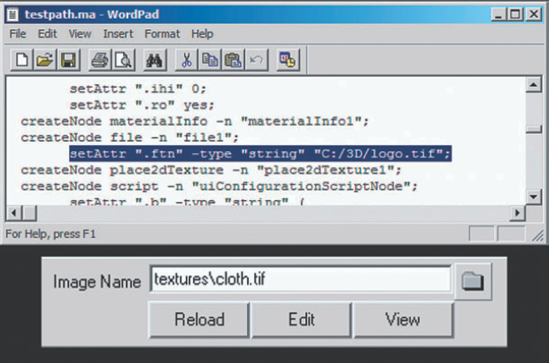
Figure 10.17. (Top) The hard-coded bitmap path of a Maya .ma file, as displayed in a text editor. (Bottom) A truncated path listed by the Image Name attribute of a File texture.
Thus, if the Maya file in question is moved between computers with different drive letters or directory structures, logo.tif will be "lost." In this case, the Multilister and Hypershade windows display a black icon for bitmaps that are missing. This holds true even if the project directory has been set through File > Project > Set. In such a situation, Maya displays a truncated path in the File texture's Image Name field (see the bottom of Figure 10.17). Nevertheless, Maya will be unable to find the texture if the drive letter or directory structure has changed.
Fortunately, you can fix this problem by quickly editing an .ma version of the file, which is simply text. Using the Find and Replace All function of Microsoft Windows WordPad or an equivalent text editor, replace c:/ with d:/ or any other appropriate path. In a similar fashion, you can edit .mb files. However, since .mb files are binary, a hexadecimal editor is required (see Figure 10.18).

Using the default image format and render resolution is rarely a good choice. To create a professional animation, you should familiarize yourself with compression schemes, image formats, and key differences between video and motion picture technology.
Maya Software, Hardware, and Vector renderers can output 30 different image formats. You can select the format by switching the Image Format attribute in the Render Settings window. Although any of the formats can be used successfully in the right circumstance, AVI, QuickTime, JPEG, Targa, and TIFF formats are perhaps the most popular. At the same time, Maya IFF, PSD, Adobe Illustrator, EPS, and SWF formats are designed for specialized tasks.
- AVI (
.avi) and QuickTime (.mov) On Microsoft Windows systems, Windows Media Player AVI movies are an available format. By default, Maya renders AVI files with no compression. However, you can choose other compression schemes by clicking the Compression button that appears just below the Image Format attribute. Although AVIs are convenient for short tests, they are not suitable for most renders. If a batch render fails or is intentionally interrupted, the AVI file is permanently lost. In addition, individual AVI frames cannot be checked as the render progresses. Conversely, the QuickTime format is available on systems running Macintosh OS X. QuickTime suffers from the same drawbacks as AVI.
- JPEG (
.jpg) Stands for Joint Photographic Experts Group and is one of the most popular image formats in the world. The main weakness of this format is the lossy quality of its compression, whereby artifacts appear along edges and other high-contrast areas. By default, Maya sets the compression quality of rendered JPEGs to 75 percent. (See the section "Changing Compression Settings" later in this chapter.) Maya does not support CMYK variations of the JPEG format.
- Targa (
.tga) Developed by Truevision in the mid-1980s, this remains a robust and reliable image format. Targas can store an alpha channel and are readable by the majority of digital image and compositing programs. Targa file sizes are relatively large, which is perhaps their main disadvantage. An average 720 × 540 Targa might take up 1.1 megabytes, while the same size JPEG with a 75 percent quality setting will be a mere 60 kilobytes. Not all Targa formats are supported by Maya.
- TIFF (
.tif) Stands for Tagged Image File Format and is another popular format developed in the mid-1980s. TIFFs can store alpha and are similar in size to Targas. The TIFF format has numerous variations and compression schemes, however, and are therefore inconsistently interpreted by various graphics programs. In fact, the mental ray renderer in Maya may return an error when unsupported TIFF variations are encountered as File textures. (Should this happen, convert the image to another format.) By default, Maya TIFFs are compressed with TIFF 6.0 compression. (See "Changing Compression Settings" later in this chapter.)
- Maya IFF (
.iff) A native format developed by Alias. While Maya's FCheck program reads the IFF format, such digital imaging programs as Adobe Photoshop and Gimp are unable to open them. On the other hand, compositing programs such as Adobe After Effects read IFF files. The IFF format can store specialized data (depth, motion, and vector).
- PSD and PSD Layered (
.psd) The standard Photoshop image format. If PSD Layered is chosen, the background color is placed on a Photoshop locked background while the objects are placed on a separate layer with transparency surrounding them. In this case, no alpha channel is provided (even if it is checked in the Render Settings window).
- AI (Adobe Illustrator;
.ai) Converts the scene into a series of editable spline paths. The Maya Vector renderer must be used to output this format. AI files can be read by Macromedia Flash authoring programs.
Note
Maya Software, Maya Hardware, Maya Vector, and mental ray renderers are unable to support all 30 image formats. For a detailed list of which renderer supports what format, see the "Supported Image Formats (Rendering)" page in the Maya Help file.
- EPS (
.eps) Stands for Encapsulated PostScript and can contain both bitmap and vector information. If rendered with Maya Software, a bitmap image is produced. If Maya Vector is used, a vector image is produced. The vector version of the EPS format can be read by Adobe Photoshop, Illustrator, and Acrobat.
- Macromedia Flash (
.swf) A vector image format. All the frames of a Macromedia Flash render are contained within a single file. You must use the Maya Vector renderer to output this format.
- RLA (
.rla) and SGI (.sgi) RLA is a legacy Wavefront image format that can store alpha and Z-depth channels. SGI is a legacy Silicon Graphics image format that supports an alpha channel.
The majority of Maya image formats operate in an 8-bit color space (8 bits in red, 8 bits in green, and 8 bits in blue, totaling 24 bits, or 16,777,216 possible colors). In the realm of consumer electronics, this color space is commonly referred to as True Color. At present, the majority of consumer monitors offer a 32-bit variation of True Color. This is a 24-bit color space with an extra 8 bits set aside as an empty placeholder (necessary for 32-bit architecture) or for alpha information. By comparison, Maya16 IFF, TIFF16, and SGI16 are three available Maya image formats that operate in 16-bit color space (16 bits per channel, totaling 281 trillion possible colors).
The human eye is popularly believed to discern 10 million color variations. As such, 16-bit color may seem like extreme overkill. However, many image-processing filters create superior results when operating at a higher bit depth. Hence, programs such as Adobe Photoshop and Adobe After Effects offer the option to work with 16-bit images. Low bit-depth errors are most commonly seen as banding (posterization), where the color transitions fail to be smooth (see Figure 10.19). Although 8-bit color space is satisfactory for many applications, 16-bit color space is superior for any project in which color and color manipulation is critical.
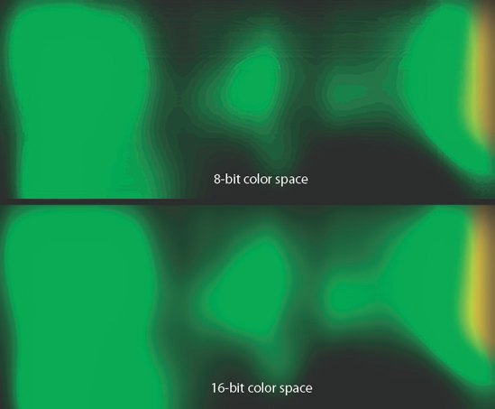
Figure 10.19. (Top) Color banding caused by a Gaussian blur in 8-bit color space. (Bottom) The result of the same blur in 16-bit color space.
Note
Maya supports several floating-point, 32-bit image formats: OpenEXR, DDS, and HDR. In addition, mental ray is able to produce 32-bit images through its Primary Framebuffer. These image formats are designed for High-Dynamic Range Images (HDRI), which are discussed in detail in Chapter 13.
To change the default compression setting of JPEG and TIFF formats within Maya, you must create an environment variable. Follow these steps:
Open a blank text file with Windows Notepad or another text editor.
To change the default JPEG compression to maximum quality, add the following line:
AW_JPEG_Q_FACTOR = 100
To remove the default TIFF or TIFF16 compression, add this line:
IMF_TIFF_COMPRESSION = none
Save the file as
Maya.envin the default Maya project folder (for example,C:Documents and SettingsusernameMy Documentsmaya2008). Be careful to capitalize the word Maya.Restart Maya. The TIFF and/or JPEG compression will be based on the environment file.
If time permits, it is always best to render larger than the default size necessitated by a particular project. For example, if an animation is to be created for a video, it is not necessary to stick to 720 × 540. Any multiplier of the 1.33 aspect ratio is equally valid. For instance, 798 × 600 or 1197 × 900 would work equally well. The use of an odd size assumes that the rendered frames will be taken into a compositing program where they can be resized. Since professional animations generally require compositing, oversized rendering can be employed quite often.
Oversized rendering guarantees an animation one very important thing—additional anti-aliasing. This anti-aliasing occurs when the oversized image is shrunk. Compositing programs such as Adobe After Effects must average the pixels of an image during a size reduction. Ultimately, this averaging reduces stair-stepping and other common aliasing problems (see Figure 10.20).

Depth of field is the range of distances that encompass objects that appear acceptably sharp. Due to the optical nature of real-world lenses and the physical qualities of the atmosphere, photography and videography rarely produce images that are 100 percent in focus. In contrast, 3D renders are always in perfect focus unless depth of field is used. You can activate Maya's depth of field by checking the Depth Of Field attribute in the Depth Of Field section of the camera's Attribute Editor tab (see Figure 10.21).
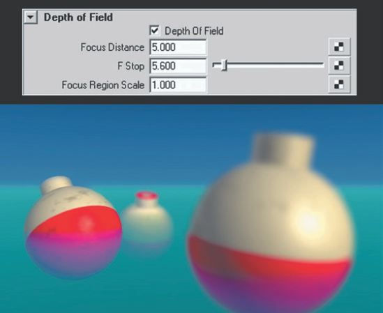
Figure 10.21. (Top) The Depth Of Field section of a camera's Attribute Editor tab. (Bottom) Depth of field in action. This scene is included on the CD as depth_of_field.ma.
Maya's depth of field, although generally convincing, can be difficult to set up at times. The following process is therefore recommended:
Measure the distance between the camera lens and subject by choosing Create > Measure Tools > Distance Tool (see Figure 10.22). For an accurate reading, place the Distance Tool's first locator at the base of the camera icon lens. Enter the resulting distance into the Focus Distance attribute field.
Set the F Stop attribute to the slider maximum of 64. The higher the F Stop value, the greater the depth of field. This will make the depth of field adjustments much easier at the start.
Render a test frame. Incrementally reduce the F Stop value and re-render. When the depth of field appears satisfactory, leave the F Stop value as is.
For fine-tuning, increase or decrease the Focus Region Scale attribute by small increments. The Focus Region Scale attribute is a multiplier of the depth of field effect.
Note
The F Stop attribute roughly approximates the f-stop of real-world cameras. F-stop is a number that represents the ratio between the diameter of the lens aperture and the focal length of the lens. F-stops are scaled by an approximate factor of 1.4 (for example, f/1.4, f/2, f/2.8, and so on). Each increased f-stop halves the open area of the aperture, halves the amount of light striking the film, and increases the depth of field. The f-stop isn't the only factor to influence depth of field, however. Depth of field is inversely proportional to the focal length of the lens and directly proportional to the distance from the camera to the subject.

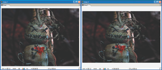
If Maya's depth of field proves unsatisfactory or too slow to render, you can simulate the effect in a compositing program. For example, in Figure 10.23 a still life is rendered with no depth of field. The image is taken in Adobe After Effects and stacked three times within a composite. The bottom layer of the composite is given a strong Gaussian blur. The middle layer has a mask applied to separate out the foreground and middle ground; the middle layer has a medium-strength Gaussian blur applied. The top composite layer has a mask applied to separate the foreground; the top layer has no blur applied. The result is an image with an artificial depth of field. If the elements within the scene are rendered out separately, this effect is even easier to achieve.

Figure 10.23. An artificial depth of field is constructed by masking multiple copies of a render and applying different strength Gaussian blurs.
In most cases, the artificial depth of field trick is successful because the human brain is unable to differentiate small degrees of "unsharpness" (technically referred to as the "circles of confusion"). That is, the incremental transition from what is in focus to what is out of focus is perceived in relatively coarse steps.
Motion blur is a streaking of objects in motion as captured by motion picture, film, or video mediums. The effect is an artifact of the time required to chemically expose film stock or electronically process light through a video CCD chip. If an object moves 1 foot during the 1/60 of a second required by a camera to create one frame, the motion blur appears 1 foot in length on that frame. Motion blur is also perceived by the human eye when the motion is rapid. Although the human brain processes information continuously and does not perceive "frames" per se, rapid motion is seen as blurry through various physiological and psychological mechanisms (the exact nature of which continues to be studied and contended).
You can check on the Motion Blur attribute in the Motion Blur section of the Maya Software tab in the Render Settings window. (mental ray motion blur is discussed in Chapter 11.) The Motion Blur Type attribute has two options—2D and 3D. 2D motion blur applies a postprocess blur to the rendered image. The blur is laid between the object's blur start and blur end position in a linear fashion. Hence, the blur is not realistic for objects spinning, weaving, or making rapid changes in direction (see Figure 10.24). Nevertheless, 2D motion blur is efficient and convincing for many animations (and the default settings work quite well).
3D motion blur, on the other hand, samples the moving object at multiple points along its path (see Figure 10.24). 3D motion blur is more accurate than 2D motion blur, but is more time consuming. Unless the anti-aliasing quality is set fairly high, 3D motion blur suffers from graininess.
Note
The 3D Blur Visib and Max 3D Blur Visib attributes (found in the Number Of Samples section of the Maya Software tab) control the number of subpixel samples used to determine if blurred objects are occluding each other.
The Blur By Frame attribute controls the time range within which the blur for one frame is calculated. The following formula is used:
Time Offset = ((Shutter Angle / 360) * Blur By Frame) / 2
The Shutter Angle attribute, found in the Special Effects section of the camera's Attribute Editor tab, emulates the shutter of a motion picture camera, which is a spinning metal disk that sits between the lens and the film gate. Shutters have a pie-shaped cut that allows light to strike the film. The cut is measured in degrees. The default 144-degree Shutter Angle value is equivalent to a standard motion picture camera that ultimately exposes a frame of film for 1/60th of a second. The larger the Shutter Angle value, the longer the exposure and the lengthier the motion blur streak. Other common shutter angles include 150 and 180.

Figure 10.24. A primitive sphere with 2D and 3D motion blur. (Arrows represent the sphere's motion vector.)
Note
You can derive the exposure duration of a frame by employing the following formula: 1 / [(360 / Shutter Angle) × frames-per-second]
If the Blur By Frame attribute is set to 1 and the Shutter Angle value is 144, the following math occurs:
((144 / 360) * 1) / 2 = 0.2
Thus, Maya looks backward in time 0.2 frames to determine the object's blur start position and forward in time 0.2 frames to determine an object's blur end position. The blur is thereby streaked between the object's blur start and blur end. This effect is clearly visible when an object makes a hard turn and 3D motion blur is used (see Figure 10.24 earlier in this section).
If you increase the Blur By Frame attribute, Maya goes back further in time and forward further in time to calculate the blur. For example, if Blur By Frame is set to 4, the following math occurs:
((144 / 360) * 4) / 2 = 0.8
If 2D motion blur is activated, the Blur Length attribute serves as a multiplier for the Blur By Frame attribute.
2D motion blur provides several additional attributes:
- Blur Sharpness
Control the sharpness of the postprocess blur. Low values increase the blur feathering and thus increase the length of the blur streak. High values reduce the blur feathering and thus shorten the length of the blur streak.
- Smooth
Helps reduce artifacts created in high-contrast situations. For example, if a dark object passes in front of a bright object or background, a dark ring may appear along the edge of the blur streak. Switching Smooth from Alpha to Color eliminates this error but continues to produce a high-quality alpha channel.
- Smooth Value
Controls the amount of blur applied to the edges of the motion blur streak. Use caution when raising this value above 2, as it may cause static objects to become blurred along their edges.
- Keep Motion Vectors
If checked, Maya stores the motion vectors but does not apply the blur. This feature is only supported by the Maya IFF image format. You can import the Maya IFF files into a compositing program such as Nuke and use the vector information to create a motion blur during the compositing stage.
- Use 2D Blur Memory Limit
If checked, places a cap on the amount of memory the blur operation is allowed to use. The number of megabytes is set by the 2D Blur Memory Limit attribute.
Note
Video cameras do not employ physical shutters. Instead, the CCD or CMOS chips are programmed to take a light sample a fixed length of time. This length is referred to as shutter speed and can vary from 1/4 to 1/2000 of a second. Shutter speed also indicates the exposure time of still film cameras.
Professional animators tend to split their renders into layers in order to make their animation projects more efficient. Not only does this habit increase the speed of individual frames, it also ensures that revisions are more easily undertaken. In addition, renders split into layers are more easily manipulated in the compositing process. Maya provides the Display Layer and Render Layer editors to help automate such a process. Detailed instructions for using these editors are included in Chapter 13. In the meantime, a demonstration of the logic involved when splitting a render into layers is included in this section.
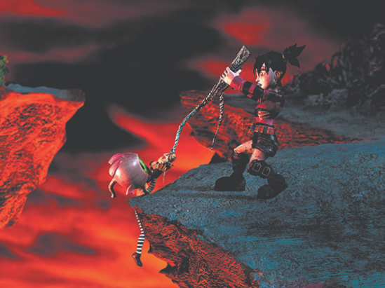
The following example is culled from a fully animated, 120-shot music video. Practically every render within the project was split into multiple layers. Although there is no hard-and-fast rule that determines how a render should be divided, the following images offer practical solutions to issues that arise during an animation production. (Note that this does not involve the splitting of the render into shading components, such as diffuse and specular. That approach is covered in Chapter 13)
Figure 10.25 represents the final composite of one shot. In the shot, a "Little Dead Girl" pulls an "Eyeball Child" up and over a cliff edge. The style is intentionally surreal with fantastic set pieces, characters, and lighting.
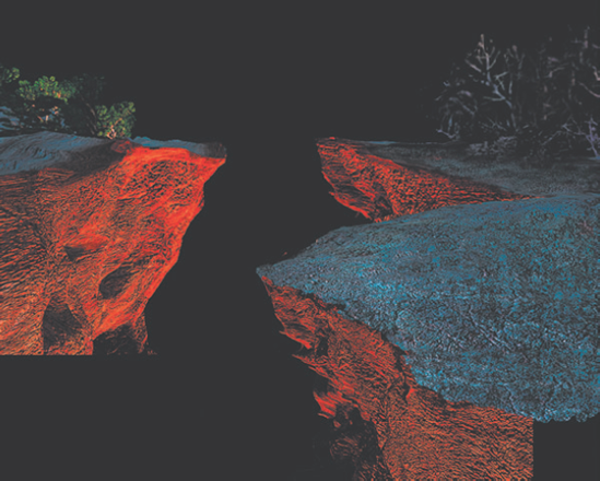
The composite begins with a render of the 3D cliff. Since the camera does not move a significant distance in the shot, only one frame of the cliff is needed. The single frame is then touched up in Adobe Photoshop. Improvements include the addition of scraggly trees in the upper-right corner and the extension of the foreground (see Figure 10.26).
The touched-up cliff is imported into an Adobe After Effects composite. The composite is set to 900 × 600, which is a custom variation of the 1.33 aspect ratio. All the renders created for the shot are kept at 900 × 600 to ensure high-quality anti-aliasing. The cliff is quickly split into parts with custom masks (see Figure 10.27). The splitting allows each part to be individually color-adjusted, blurred, and moved into a new position. Specific improvements include an artificial depth of field, trimmed trees in the upper-right corner, and a greater distance between the left and right side of the canyon. A clip-art photo of a sunset sky, color-corrected and blurred, is placed behind the cliff. Since the sky is kept separate, its positional information is keyframed, thereby allowing the clouds to "drift" during the shot.
At this point, the renders of the girl and child are brought into the composite. The girl is rendered by herself, as is the child. This separation allows for greater flexibility in the composite (in addition to speeding up the individual renders).
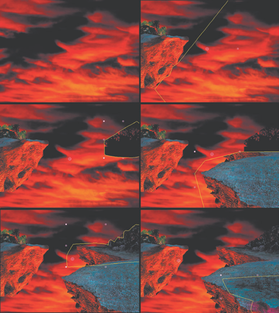
Figure 10.27. The cliff is imported into After Effects, split into parts, adjusted, and reassembled.
Errors in the character setup cause the heroine's left knee to intersect badly with her left boot. To avoid re-rigging, her left boot is rendered separately and placed at a higher composite level (see Figure 10.28). An aesthetic determination also necessitates the rerender of the child with a larger version of the doll he carries. This new render is combined with the old render with the help of a custom mask.
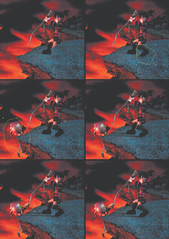
Figure 10.28. Character and shadow renders are imported into After Effects and combined using custom masks.
Shadows are rendered by themselves. To do this, all surfaces in the Maya scene are temporarily assigned to a Use Background material (see Chapter 4 for more information). In this case, the shadows appear in the alpha channel while the RGB channels are pitch black. The shadow renders are dropped directly on top of the cliff layers (see Figure 10.28). Reduced opacity and an additional blur in the composite ensure that the shadows remain fairly subtle. In this case, the shadows are not motivated by a particular light source—they are simply added to give the girl a stronger connection to the ground.
The first composite is placed into a second composite. The second composite is set to 720 × 480 so that the output is ready for digital video editing. Since the first composite was significantly larger, the shot is reframed to improve the composition and avoid parts of the cliff render that remain unfinished (see Figure 10.25 earlier in this section). In addition, the first composite is moved and keyframed within the second composite, thus creating a subtle artificial camera movement.
Conceivably, all the steps of this particular composite can be avoided by rendering the entire shot in one 3D pass. However, such an accomplishment would require additional 3D setup and refinement. Although careful preparation should always be a goal in animation, it is not always feasible due to time and resource limitations. Thus, the composite offers a "quick and dirty" way to fix mistakes and "sweeten" the quality of the renders at hand.
