Global Illumination and Final Gather are powerful rendering methods that duplicate many of the physical and optical events common to the real world. For example, the Caustics attribute re-creates reflected specularity. Irradiance attributes, found on standard Maya materials, illuminate a scene in which no lights are present. Global Illumination and Final Gather are available through the mental ray renderer. In addition to a long list of specialized attributes, mental ray provides custom mental ray shaders.
Chapter Contents
Exploring Global Illumination and photon tracing theory
Using the Caustics attribute
Applying mental ray shaders
Using Final Gather and irradiance attributes
Fine-tuning mental ray renders
Global Illumination is a lighting process in which virtual photons are absorbed by or reflected off surfaces in a scene. This process is equivalent to naturalistic lighting in which light "bounces" off one surface to the next. (For information on lighting theory, see Chapter 1.)
Although raytracing can trace light paths, the raytrace renderer is unable to mingle colors in a scene. For instance, in the real world, a brightly lit red object will "bleed" red onto the white of a tabletop (see Figure 12.1).

Figure 12.1. Indirect illumination causes the red of an object to "bleed" onto the white of a tabletop.
Raytracing and scanline rendering depend on direct illumination techniques. Global Illumination, on the other hand, uses indirect illumination. To properly describe indirect illumination, along with color bleeding, a closer look at the mechanics of light is necessary.
Light is a form of electromagnetic radiation that exists as a continuous range of wavelengths. Specific wavelengths are visible to the human eye and are perceived by the human brain as specific colors. At the same time, light is quantified as elementary particles called photons, which are discrete units of light energy. When a light wave with a particular wavelength strikes an object, it is absorbed, reflected, or transmitted. Absorption occurs when the energy of a photon is captured by an atom. The capture causes an orbiting electron to temporarily jump to a higher energy level. As the electron returns to a lower energy level, it releases the excess energy as a new photon, which equates to a longer wavelength of radiation. The longer wavelength is felt as radiant heat.
Note
The wave-particle duality of light, to this day, is actively researched and debated. For the sake of simplicity, you can think of light as simultaneously exhibiting properties of a wave and a particle. For 3D animation, critical components of light include light direction, light wavelength (Color and Photon Color), and light energy (Intensity and Photon Intensity).
Transmission, on the other hand, occurs when the photon is absorbed by an atom at a material boundary. The energy is not released by the material immediately, however. Instead, the energy is transferred from one atom to a neighboring atom. This continues until the energy is passed through the bulk of the material to an opposite material boundary. At the opposite boundary, the energy is released as a photon with energy similar to the original photon. Since the energy, and the wavelength, is inherently the same, the light remains visible. Thus, transmission makes glass and similar materials transparent.
Note
All transparent materials incur some degree of refractivity. Refraction occurs when a light wave crosses the boundary between two materials with different refractive indices. As the wave enters the second material, its wavelength, speed, and direction are altered. Hence, refracted objects appear bent or broken. For more information on refraction and refractive indices, see Chapters 7 and 11.
Ultimately, color is not contained within the materials of objects. Instead, color is the result of particular wavelengths of light reaching the viewer through reflection or transmission. Different materials (wood, stone, metal, and so on) have different atomic compositions and thereby absorb, reflect, and transmit light differently. Hence, the red of a red object represents a particular wavelength that the object reflects. In the scenario illustrated in Figure 12.1, the white light of a light source is reflected off the object as a red wavelength. (White light contains the full spectrum of color wavelengths; therefore, the non-red wavelengths are absorbed and converted to radiation interpreted as heat.) The reflected red wavelength strikes the white table, which is made of a different material and has a different atomic structure. Nevertheless, the table reflects pink wavelengths that are closely related to the original red of the object.
Global Illumination can replicate the absorption, reflection, and transmission of light and the resulting mingling of colors. Hence, the system can produce extremely realistic renders.
Note
Wavelength is the distance between repeating features of a waveform cycle. Frequency is the number of cycles that occur during a particular period of time. When discussing light, frequency is explicitly dependent on the wavelength and speed of the light wave (roughly 300,000 kilometers per second). Hence, the formula is frequency = speed of light / wavelength.
To use Global Illumination, you must use the mental ray renderer. In addition, you must employ virtual photons. In Maya, spot, point, area, and directional lights generate photons when the light's Emit Photons attribute is checked (see Figure 12.2). (You can find Emit Photons in the Caustic And Global Illumination subsection of the mental ray section in the light's Attribute Editor tab.)

When a scene is rendered, photons are traced from each photon-emitting light to objects in the scene. If a photon "hits" a surface, it is absorbed, reflected, or transmitted (refracted) based on the qualities of the material assigned to the surface. If a photon is reflected or transmitted, it survives with only a portion of its original energy. The amount of energy is determined by the reflection coefficient, which is established by the Reflectivity attribute in Maya.
To simplify the photon-tracing process, many Global Illumination systems, including the one employed by mental ray, randomly cull photons in a process known as Russian Roulette. Photons that survive a surface hit through reflection or refraction are given an increased energy that is proportional to the potential energy of all the photons generated by the light source. The photons that are culled and thereby absorbed by the surface have their position, incident direction, and energy stored in a special photon map. The following scenario is a simplified example of the process:
A light generates 1,000 photons, each with an energy level of 10. The net photon energy is 10,000.
The photons strike a surface that is assigned to a material with Reflectivity value set to 0.5.
With the Russian Roulette method, 50 percent of the photons are absorbed and thus contribute their energy to the photon map. The surviving 500 photons reflect off the surface with their original energy level of 10. The surviving net energy is 5,000, or 50 percent of the original net energy of 10,000.
If the Russian Roulette method is not used, 1,000 photons reflect with a 50 percent energy level, which correlates to the Reflectivity value of 0.5. The net energy level remains at 5,000. However, the calculations are more complex because 1,000 photons must be traced instead of 500.
The absorption, reflection, or transmission of a photon is affected by the shading components of the assigned material. Not only will changes to the Diffuse and Reflectivity attributes affect photon scattering, but Color, Eccentricity, and Specular Color have an equal impact. If a photon survives a hit and is reflected or transmitted, it continues through the scene until it hits another surface. Once again, the photon is absorbed, reflected, or transmitted. This process continues until the surviving photons are stopped by the Max Photon Depth attribute, which defines the number of hits permitted per photon. (Max Photon Depth is located in the Caustics And Global Illumination section of the mental ray tab in the Render Settings window.) Ultimately, the information stored in the photon map is combined with the direct illumination model, which in turn determines the color and intensity of each rendered pixel.
The number of photons generated by a given light is set by the light's Global Illum Photons attribute. You can lower or raise the default value of 10,000 to decrease or increase quality. In addition, you can change the qualities of photons generated by a light with the following attributes (all of which are found in the Caustic And Global Illumination subsection of the mental ray section in the light's Attribute Editor tab):
- Photon Color
Represents the red, green, and blue components of a photon's energy. Photon Color is a "dummy" attribute. The RGB values of its color swatch are multiplied by the Photon Intensity attribute to produce Energy R, Energy G, and Energy B attributes. You can access these attributes in the Script Editor (for example,
getAttr light.energyR;).- Photon Intensity
A scaling factor used to determine the intensity of photons produced by a light. The default value of 8000 tends to be too high and will often wash out a render. A value of 0 will turn off photon tracing for the light. Photon Intensity should be changed through the Attribute Editor and not through the Script Editor or with a MEL script.
- Exponent
Simulates light falloff over distance. The default value of 2 replicates natural, quadratic decay. A value of 1 effectively prevents falloff from occurring. Values higher than 2 create a more rapid falloff by artificially decreasing photon energy with distance.
You can create a simple Global Illumination render with the following steps:
Create a still life. Create a spot light and position it over the still life. Open the spot light's Attribute Editor tab. Check the Emit Photons attribute in the Caustic And Global Illumination subsection (found in the mental ray section).
Assign the objects to colored Blinn materials. To simplify the process, do not adjust the materials' Transparency attributes.
Open the Render Settings window. Change Render Using to mental ray.
Switch to the mental ray tab. In the Secondary Effects subsection of the Rendering Features section, check Raytracing (if it's not already checked). Raytracing remotely activates the Ray Tracing attribute in the Raytracing section of the same mental ray tab. The raytracing process is mandatory for Global Illumination.
In the Secondary Effects subsection of the Rendering Features section, check Global Illumination. Global Illumination remotely activates the Global Illumination attribute found in the Caustics And Global Illumination section in the same mental ray tab.
Render a test through the Render View.
To save time, you can change the Quality Presets attribute to Preview: Global Illumination, which automatically activates Raytracing and Global Illumination in the Secondary Effects subsection and the Caustics And Global Illumination section. (For more information on the Rendering Features section, see Chapter 11.)
Global Illumination will often create a spotty render. Fortunately, you can fix this by adjusting such attributes as Radius and Accuracy, which are discussed in the next section of this chapter.
Keep these additional tips in mind when working with Global Illumination:
To contribute photon information to the photon map, a surface must be assigned to a material that has a Diffuse attribute. The material's Color value must be higher than 0, 0, 0.
The first surface that a photon hits is ignored in the creation of a photon map. Nevertheless, the first hit is considered part of the direct illumination calculation.
Although directional lights can generate photons, they are not recommended. Directional lights possess direction, but no true position. Therefore, when tracing photons, a potentially large numbers of photons may never reach the geometry of the scene and the render is thereby made inefficient.
Global Illumination works more efficiently with mental ray if there is a complete set. That is, if there is empty space within the scene, some photons may never strike a surface and thus serve no purpose.
Global Illumination attributes are contained within the Caustics And Global Illumination section of the mental ray tab in the Render Settings window (see Figure 12.3). Of all the attributes, Radius and Accuracy are perhaps the most critical for creating a refined render.
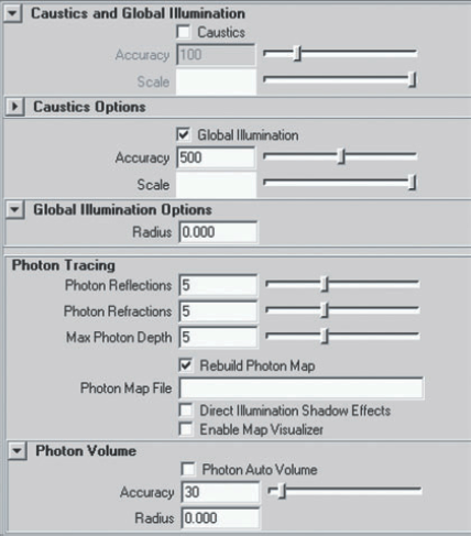
Figure 12.3. The Caustics And Global Illumination section of the mental ray tab in the Render Settings window
- Radius
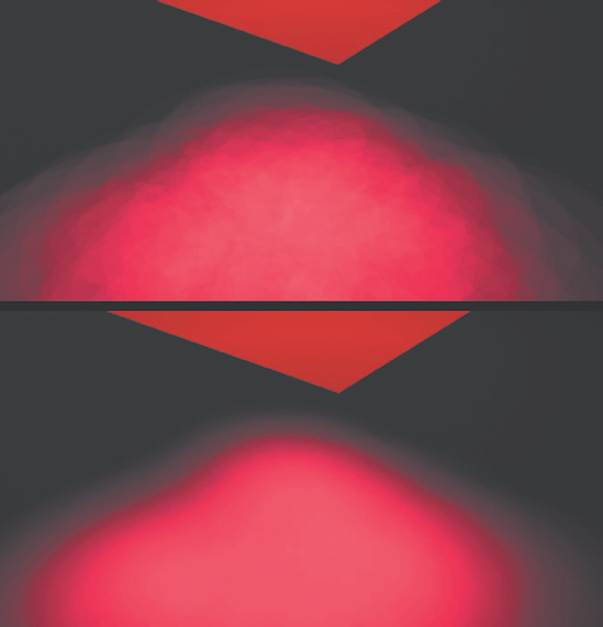
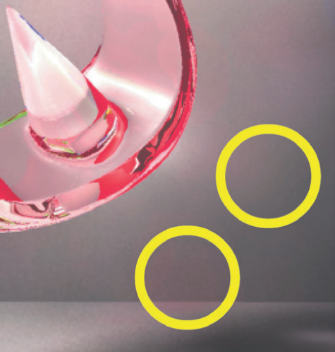
Found within the Global Illumination Options subsection, Radius controls the maximum distance from a photon hit that the renderer will seek out neighboring photon hits to determine the color of the hit in question. The default value of 0 allows Maya to automatically pick a radius based on the scene size. Although the default value produces a satisfactory render in many cases, it will often create spottiness (see Figure 12.4). The spottiness is exaggerated in scenes containing complex reflective or refractive surfaces, as the photons are scattered to an even greater degree.
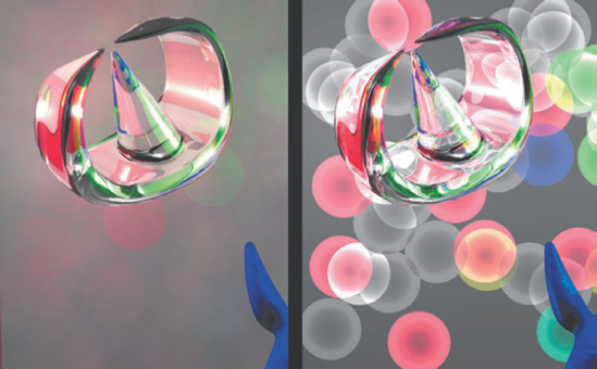
Figure 12.4. Photon hits appear as colored circles. For the left render, each of the two lights generates 10,000 photons. For the right render, each of the two lights generates 200 photons.
In this situation, each circle corresponds to the location of one photon hit. The color of a given circle, however, is derived from the average energies of all the photon hits discovered within the circle. The areas in-between the circles receive no indirect illumination and are thus darker. The circles vary in color because the photon energy levels, stored as RGB, are influenced by the Color value of the materials they encounter while reflecting off and transmitting through surfaces. For example, if a material is green, the energy of the reflected or transmitted photon is biased toward green. Hence, the mingling of colors and color "bleeding" is possible.
Ideally, the individual photon hits should not be visible in the render but should blend seamlessly with each other and the direct illumination. If the default Radius value is producing spottiness, the following steps are recommended:
Gradually increase the Global Illum Photons for each photon-producing light.
If higher Global Illum Photons values are unable to improve the quality without drastically effecting the render time, manually set the Radius attribute. As a rough rule of thumb, set Radius to a value equal to this formula:
[Scene bounding box height] / ([Total number of photons] / 5000)
Gradually increase the Radius value until the photon hits begin to disappear.
Gradually increase the Accuracy value to further blend overlapping photon hits. If Accuracy has no significant impact on the render, continue to raise the Global Illum Photons and Radius values.
If a few photon hits remain visible despite high Global Illum Photons, Radius, and Accuracy values, consider using Final Gather (which is described later in this chapter). Final Gather does an excellent job of smoothing out Global Illumination renders.
Balancing the number of photons in a scene with the Radius value is an important aspect of the Global Illumination process. An excess of photons will cause a redundant overlapping of photon hits and an unnecessarily slow render. On the other hand, a limited number of photons with a large Radius will lead to inaccurate indirect lighting calculations.
Note
If the proper photon balance is elusive, try the Diagnose Photon tool. The Diagnose Photon tool and Diagnostics section of the mental ray tab are described in section 12.2 of the Additional_Techniques.pdf file on the CD.
- Accuracy
Found within the Caustics And Global Illumination section (directly below the Global Illumination check box), Accuracy sets the maximum number of neighboring photon hits included in the color estimate of a single photon hit. The search for neighboring photon hits is limited to the region established by the Radius attribute. In general, the higher the Accuracy value, the smoother the result. However, Accuracy only affects overlapping photon hits. That is, if the photon count is low or the Radius value is small so that the photon hits do not significantly overlap, the Accuracy attribute will have no effect on the render.
- Scale
Found within the Caustics And Global Illumination section (below the Global Illumination check box), Scale serves as a multiplier for the Photon Intensity attribute of all lights in the scene. If the slider is set to 50 percent gray, all the photons in the scene will be at half intensity.
- Rebuild Photon Map
Found within the Photon Tracing subsection, Rebuild Photon Map determines whether photon maps are rebuilt for each render. This attribute should be left checked unless the lighting is finalized and there is no object motion in the scene. If unchecked, this attribute will look for the photon map listed in the Photon Map File attribute field.
- Photon Reflections and Photon Refractions
Found within the Photon Tracing subsection, Photon Reflections defines the maximum number of times a photon will reflect in a scene. This attribute is overridden by the Max Photon Depth attribute. The first surface encountered is not included in the count. Photon Refractions functions in the same manner but affects the maximum number of photon refractions.
- Max Photon Depth
Found within the Photon Tracing subsection, Max Photon Depth sets the maximum number of times a photon can reflect or refract in a scene.
- Direct Illumination Shadow Effects
Found within the Photon Tracing subsection, this attribute allows raytraced shadows to maintain transparency. When Direct Illumination Shadow Effects is unchecked, raytrace shadows remain opaque despite material transparency.
Although mental ray provides a Preview: Global Illumination option for the Quality Presets attribute, it does not provide a high-quality preset. Therefore, attributes should be raised individually to improve the render. For example, you can incrementally raise the Accuracy from 64 to 1024 to smooth out photon hits (see Figure 12.5).
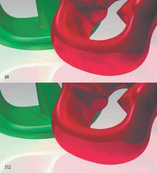
Figure 12.5. (Top to Bottom) Accuracy set to 64 and 512. This scene is included on the CD as simple_global.ma.
Enable Map Visualizer and Photon Map File attributes are discussed in the next section. Accuracy and Radius, as found in the Photon Volume subsection, are detailed in "Preparing mental ray Shaders for Global Illumination" later in this chapter.
Unfortunately, photon maps cannot be viewed with FCheck. Photon maps are not image files, but are data files that contain a 3D spatial search structure called a kd-tree. The kd-tree stores the location, incident direction, and energy of each absorbed photon. Nevertheless, mental ray provides a special window to examine data with the maps. Follow these steps:
Check the Enable Map Visualizer attribute in the Photon Tracing subsection of the Caustics And Global Illumination section of the mental ray tab. Enter a name in the Photon Map File attribute field.
Render a test frame using Global Illumination.
Choose Window > Rendering Editors > mental ray > Map Visualizer. The mental ray Map Visualizer window opens. Generally, the new photon map is preloaded into the Map File Name attribute field. If not, click the browse button and retrieve the photon map from the following directory:
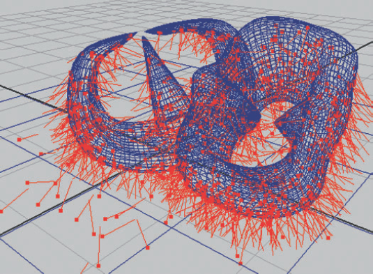
project_directory/renderData/mentalray/photonMap/As soon as a valid photon map file is loaded, photon hits are rendered as colored points in the workspace view (see Figure 12.6).
You can control how photon hits are displayed by changing various settings within the mental ray Map Visualizer window (see Figure 12.7). Sections and attributes of the Map Visualizer window include Photon Visibility, Point Size, Normal Scale, and Direction Scale.
- Photon Visibility
A section that contains the Globillum Photons, Caustic Photons, and Volume Photons attributes. You can check or uncheck these in any combination to preview Global Illumination, caustic, and volume photon hits. For a description of caustic photons, see the next section in this chapter. For a discussion of volume photons, see "Preparing mental ray Shaders for Global Illumination" later in this chapter. Photon Visibility does not indicate first-surface hits, as they are considered part of the direct illumination calculation.
- Point Size
Changes the screen size of the points used to represent photon hits.
- Normal Scale
Displays and scales the surface normals at each photon hit.
- Direction Scale
Displays and scales lines that represent the motion vectors (incident directions) of photons before their individual hits (see Figure 12.6).

The Search Radius Scale attribute is designed for Final Gather renders utilizing irradiance and is discussed in "Using Irradiance" later in this chapter.
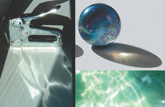
A major advantage of the mental ray renderer is its ability to provide caustics. Caustics are "hot spots" resulting from light rays focused by the specular properties of materials. For example, caustics are commonly produced by shiny metal, water, and glass (see Figure 12.8). If a 3D material does not possess specular properties, no caustics will be generated by that material.
A special set of caustic photons are used to create caustics in Maya. A caustic photon is emitted by a light in a prerendering process and is traced through the scene until it is reflected or refracted a maximum number of times set by the Max Photon Depth attribute. If a caustic photon encounters a diffuse, nonreflective, nonrefractive surface, it is absorbed and its energy contribution is stored in a photon map.
Global Illumination photon maps do not store specular reflection and specular refraction information. Nevertheless, if the Caustics and Global Illumination attributes are checked for a render, the caustic photon and Global Illumination photon information is stored side by side in the same file. You can view the caustic photon hits with the mental ray Map Visualizer window. (See the section "Reviewing Photon Hits" earlier in this chapter.) You can render caustics without Global Illumination if need be. You can activate caustics by checking either the Caustics attribute in the Secondary Effects subsection or the Caustics And Global Illumination section of the mental ray tab in the Render Settings window (both attributes are linked).
The number of caustic photons generated by a given light is set by the Caustic Photons attribute in the Caustic And Global Illumination subsection of the light's Attribute Editor tab. The Caustics And Global Illumination section of the mental ray tab also includes the following caustic attributes:
- Accuracy
Found in the Caustics And Global Illumination section (directly below the Caustics attribute check box), Accuracy sets the maximum number of neighboring caustic photon hits included in the color estimate of a single caustic photon hit. Higher values produce smoother caustics.
- Scale
Found in the Caustics And Global Illumination section (below the Caustics attribute check box), Scale serves as a multiplier for the intensity of the caustic. If the attribute is 50 percent gray, the intensity of the caustic is halved. This attribute can also be tinted a color, such as red. If Scale is left white, the resulting caustic color may not match the color of the object creating it.
- Radius
Found in the Caustics Options subsection, Radius controls the maximum distance from a caustic photon hit that the renderer will seek out neighboring caustic photon hits to determine the color of the hit in question. The default value of 0 allows Maya to automatically pick a radius based on the scene size. An improperly sized Radius will produce spottiness similar to that afflicting Global Illumination. That said, it is not necessary to match the two Radius attributes in the Caustics Options and Global Illumination Options subsections. In general, caustic photon hits occur in small pockets and are not as spread out as their Global Illumination counterparts. Nevertheless, stray caustic hits will occasionally pepper a render. Hence, great care should be taken when balancing the Caustic Photons and Radius attributes (see Figure 12.9).
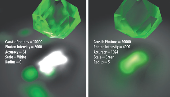
Figure 12.9. Different combinations of Caustic Photons, Photon Intensity, Accuracy, Scale, and Radius attributes create different degrees of caustic detail. This scene is included on the CD as
caustics.ma.The Radius attribute is distorted by the refractive quality of a material. That is, the screen size of the caustic photon hit will vary when the material's Refractions attribute is checked and the Refractive Index value is set to a value other than 1. This creates additional difficulties when blending the photon hits.
An additional approach, as suggested by Maya's documentation, requires these two steps:
Incrementally increase Radius until there is little change in the render.
Incrementally increase Accuracy until the caustic is suitably smooth.
- Caustic Filter Type
Found in the Caustics Options subsection, this attribute controls the sharpness of the caustic with the application of a filter. The Box and Gauss options produce sharper caustic edges, while the Cone option produces softer results. The effect is subtle unless the total number of photons used in the scene is fairly low (see Figure 12.10).
- Caustic Filter Kernel
Sets the size of the filter determined by the Caustic Filter Type attribute. The higher the value, the sharper the result; this is most noticeable with the Cone filter option.
Aside from Radius and Refractive Index attributes, Eccentricity, Specular Color, and Reflectivity attributes of involved materials affect the look of the caustic. For example, in Figure 12.11 changes to the Refractive Index, Eccentricity, and Reflectivity of a semitransparent surface lead to fairly substantial variations.

By default, mental ray works with all standard Maya materials. Nevertheless, a large number of mental ray shaders are included with the program. You can find these in the Create mental ray Nodes menu in the Hypershade window or in the mental ray tab of the Create Render Node window. You can assign a mental ray shader to a surface as you would a Maya material. However, you must use the mental ray renderer for the shader to be utilized. In addition, many of the attributes of the mental ray shaders are not intuitive and don't correspond to their Maya counterparts. Thus, descriptions of the most useful shaders and their attributes follow.
The Dgs_material shader provides a physically-accurate shading model by offering Diffuse, Glossy, and Specular attributes. Diffuse represents the diffuse component and determines the base color of the surface. Glossy and Specular control the look of reflections and refractions when raytracing; you can use them individually or in conjunction.
If Glossy is set to black, Specular controls the intensity of the reflection or refraction. The higher the Specular value, the more intense the reflection or refraction. The Specular attribute will not create specular highlights.
If Specular is set to black, Glossy controls the intensity of the reflections, refractions, and specular highlights. The higher the Glossy value, the more intense the reflection and refraction and the larger the specular highlight. In addition, Glossy provides distance-based degradation of reflections and refractions. The degradation is controlled by the Shiny attribute. High Shiny values create a sharp reflections and refractions for objects close to the assigned surface. Low values create the opposite effect. For example, in Figure 12.12, a cylinder is intersected with a plane that is assigned to a Dgs_material. In left render, the reflection and refraction of the cylinder are controlled by the Specular attribute and are thus sharp. In the right render, the reflection and refraction are controlled by the Glossy and Shiny attributes; the reflection and refraction are sharp near the intersection point, but quickly degrade as they travel farther away.
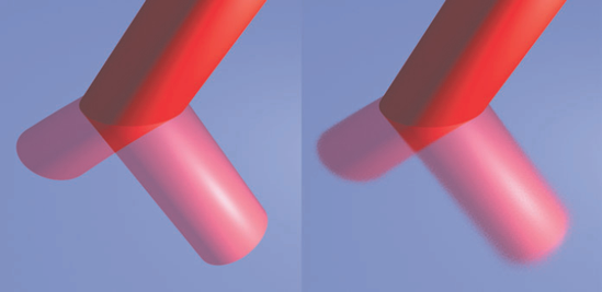
Figure 12.12. (Left) Dgs_material with reflection and refraction controlled by Specular attribute. (Right) Same material with reflection and refraction controlled by Glossy attribute. This scene is included on the CD as dgs_material.ma.
If Shiny is set to 0, Shiny U and Shiny V are enabled. Shiny U and Shiny V control the U and V scale of an anisotropic glossy highlight. The Transp attribute determines the transparency. The Index Of Refraction attribute sets the material's index of refraction (this is called Ior in version 8.5).
If Specular and Glossy are used in conjunction, their values are added together and thus produce more intense reflections and refractions. However, the sharpness of the reflection or refraction is controlled by Glossy and Shiny. Glossy, as a 3D term, refers to a surface that creates imperfect reflections (one that is less smooth than a specular surface and less rough than a diffuse surface).
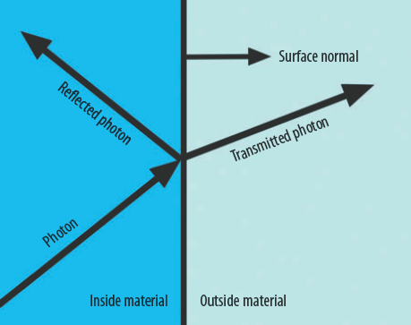
The Dielectric_material shader re-creates a material that is a poor conductor of electricity. Real-world dielectric materials include ceramics, plastics, glass, and some liquids, such as water. In addition, the Dielectric_material shader replicates the interaction between photons and dielectric material boundaries (known as interfaces). Based on angles of incidence and refractive indices of the involved interface materials, a photon will either transmit (refract) through the second material or reflect internally through the first material (see Figure 12.13). The shader refers to the first material as the "inside" material and the second material as the "outside" material. The shader employs Fresnel equations and Snell's Law to determine transmission and reflectance qualities (for more information, see Chapter 4).
For additional realism, the shader incorporates Beer's Law, which relates the absorption of light by a material to the properties of the material. Thus, the Dielectric_material shader is perhaps the most physically accurate material available in Maya. The attributes for Dielectric_material follow:
- Col
Represents the percentage of light that will not be absorbed when traveling through one world unit of the base or "inside" material. For example, if Col is set to 0.9, 10 percent of the light is absorbed per world unit.
- Index Of Refraction
The index of refraction for the inside material (called Ior in version 8.5).
- Outside Color
If Outside Color is set to default white, the interface is assumed to be dielectric-to-air. Thus, the "outside" material, which is air, does not cause a loss of light energy. If Outside Color is set to a color other than white (which equates to a value other than 1), the interface is assumed to be dielectric-to-dielectric. Thus, Outside Color represents the percentage of light that will not be absorbed by the outside material that light interacts with after exiting the inside material. The location of the outside material is defined by the normals of the assigned surface (see Figure 12.13). (This attribute is called Col_out in version 8.5.)
- Outside Index Of Refraction
The refractive index of the outside material (called Ior_Out in version 8.5).
- Ignore_normals
Bases the entry or exit of light rays through a material on a fixed number and not the alignment of the normals on the surface. This attribute may produce superior results if the model is intricate or otherwise poorly crafted.
- Phong Coefficient
Controls the intensity of the specular highlight.
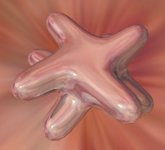
Due to its physical accuracy, the Dielectric_material shader has a natural advantage when rendering glass. For example, when the water glass created in Chapter 11 is assigned to a Dielectric_material, it gains more accurate caustic hot spots at the base (see Figure 12.14). Global Illumination is not required.
The main disadvantage of Dielectric_material, and many other mental ray shaders, is the limited number of available attributes. For instance, there's no interactive way to alter the shape or color of the specular highlight of a Dielectric_material shader.
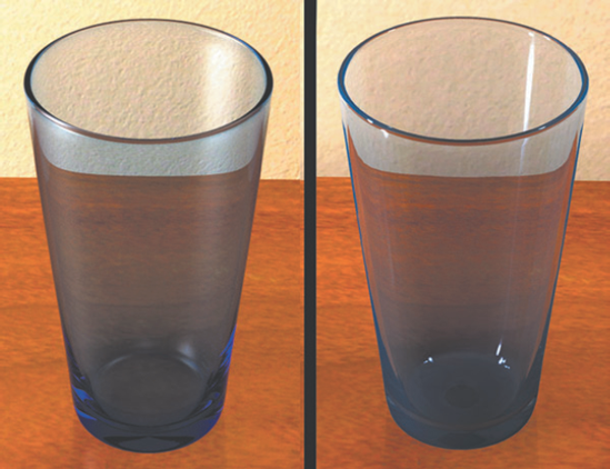
Figure 12.14. (Left) The water glass assigned to a Dielectric_material shader. (Right) The same glass assigned to an Anisotropic material. The left scene is included on the CD as dielectric_glass.ma.
Note
If you are replicating a glass filled with liquid, three different Dielectric_ material shaders are necessary. The first shader, assigned to the outside surface of the glass, re-creates the dielectric-to-air interface. The second shader, assigned to the portion of the liquid surface that touches the air, re-creates a separate dielectric-to-air interface. The third shader, assigned to the portion of the glass surface that touches the liquid, re-creates the dielectric-to-dielectric, liquid-to-glass interface.
Shaders that carry the "Mib" prefix represent common shading models. "Mib" shaders are found in the Materials section of the Create mental ray Nodes menu.
Mib_illum_lambert, Mib_illum_blinn, and Mib_illum_phong are stripped-down variations of their namesakes. Each of the shaders carries a Diffuse attribute, which is similar to the attribute carried by Maya materials. Since "Mib" shaders do not possess a Color attribute, you must adjust the Diffuse attribute to change the color. In addition, Mib_illum_lambert, Mib_illum_blinn, and Mib_illum_phong offer Ambience and Ambient attributes. Ambience is a multiplier for Ambient, which is equivalent to the Ambient Color attribute used by Maya materials.
Mib_illum_blinn adds Roughness and Index Of Refraction attributes. Roughness controls the size of the specular highlight. Index Of Refraction does not require transparency or raytracing to function; instead, it emulates the index of refraction that all real-world materials possess, including solids such as metals. (For example, titanium has a 2.16 refractive index.) Index Of Refraction affects the intensity of the specular highlight. To create an intense specular highlight with Mib_illum_blinn, raise Index Of Refraction above the default maximum of 2 and lower the Roughness value.
Mib_illum_phong is similar to Mib_illum_blinn, but replaces Roughness and Index Of Refraction with the Exponent attribute, which controls the size of the specular highlight.
Mib_illum_cooktorr uses the Cook-Torrance shading model and is a physically-based shader. The color of the shader's specular highlight is dependent on the material quality, light color, and the light's incident angle to the assigned surface. Thus, if the surface is animated, the specular highlight is prone to shift in color as it appears at different points along the surface. Mib_illum_cooktorr offers additional control over the specular highlight quality by splitting the Index Of Refraction into Red, Green, and Blue channels. You can assign a different value to each channel and thus make the highlight sensitive to light color. For example, if the light color is pure red and the Index Of Refraction Red attribute is set to 20, the highlight is intense. However, if the light shifts to a green color and the Index Of Refraction Green attribute is set to 1.5, the highlight is dull.
"Mib" shaders share the Mode attribute, which serves as a per-material light-linking system (see Figure 12.15). You can map lights and thereby list them with the Lights[n] attribute of the "Mib" material. You can follow two methods to achieve this:
In the Light Linking section of the shader, switch Mode to Inclusive Linking or Exclusive Linking. The Lights subsection appears. Click the checkered Map button beside the Lights[0] attribute. The Create Light window opens. Select a light type from the list. The light is created at 0, 0, 0 and is listed in the Light[0] field.
As an alternative, open the Hypershade window. MMB-drag the shader into the work area. Open the Hypergraph Hierarchy window. MMB-drag a light transform node into the Hypershade work area and drop it on top of the shader icon. Choose Other from the Connect Input Of menu. The Connection Editor opens. In the left column, click Message. If Message is not visible, choose Left Display > Show Hidden from the Connection Editor menu. In the right column, click Lights[0] (listed under Lights). Exit the Connection Editor. The light is listed in the Lights[0] field of the shader's Attribute Editor tab. Each time you connect a light, a new Lights[n] attribute appears, where n is a consecutive number.

Figure 12.15. The Mode attribute and Lights section of a "Mib" shader. Four lights are listed with the shader.
If Mode is set to Inclusive Linking, only the lights listed with the shader are used to render the assigned surface. If Mode is set to Exclusive Linking, only the lights not listed with the shader are used to render the assigned surface. If Mode is set to the default Maya Linking, standard Maya linking, as determined by the Relationship Editor, is utilized.
With Maya 8.5, the Mode attribute is dependent on numeric values. If Mode is set to 0, all the lights in the scene are used to render the shader. If Mode is set to 1, only the lights listed with the shader are used. If Mode is set to 2, only lights not listed with the shader are used.
"Misss" shaders undertake subsurface scattering (SSS) by allowing light to penetrate the surface of a translucent object. Translucency is emulated by the Translucence, Translucence Depth, and Translucence Focus attributes of common Maya materials, but is not as physically accurate as "Misss" shaders. Seven "Misss" shaders are offered by mental ray; the most commonly used ones are detailed in this section.
The Misss_fast_simple_maya shader follows its name by providing efficient SSS renders. To apply this shader, follow these steps:
Create a primitive surface. Create a light and place it behind the surface so it points through the surface toward the perspective camera.
Open the Hypershade window. Switch the Create Maya Nodes menu to Create mental ray Nodes by clicking the down arrow above the left column of material icons. Click the Misss_fast_simple_maya icon. A custom network is automatically created by Maya. Select the Misss_fast_simple_maya shader icon in the Materials tab and assign it to the surface. Create a test render with mental ray. The light penetrates the surface.
To reduce the distance through the surface that the light penetrates, open the Misss_fast_simple_maya shader in the Attribute Editor and reduce the Back SSS Depth attribute (in the Subsurface Scattering Layer section). For example, at the left of Figure 12.16 only a portion of a polygon shape receives scattered light; Back SSS Depth is set to a value less than the length of the shape.
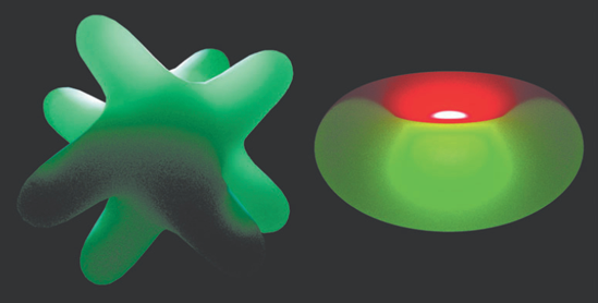
Figure 12.16. (Left) Due to a small Back SSS Depth value, only a portion of a polygon shape receives scattered light. This scene is included on the CD as
misss_shape.ma.(Right) Front SSS Color, set to red, and Back SSS Color, set to green, tints a torus. This scene is included on the CD asmisss_torus.ma.To adjust the color of the surface that receives no scattered light, change Diffuse Color (in the Unscattered Diffuse Layer section). To adjust the specular highlight, adjust the Specular Color and Shininess attributes (in the Specular Layer section). To alter the color of the penetrating light, change Front SSS Color and Back SSS Color (in the Subsurface Scattering Layer section). Front SSS Color determines the color of the scattered light as it enters the surface. Back SSS Color determines the color of the scattered light as it exits the surface. (Front SSS Color and Back SSS Color are dependent on the camera's point-of-view.) For example, at the right of Figure 12.16 a light is placed in the center of a torus. Front SSS Color is set to red and Back SSS Color is set to green.
To remove graininess from the image, expand the Lightmap section and slowly increase the Samples attribute by powers of 2 (32, 64, 128, 256, and so on).
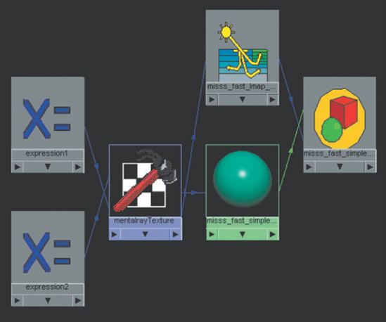
The network created for Misss_fast_simple_maya, illustrated by Figure 12.17, is similar to those created for Misss_fast_skin_maya and Misss_fast_shader. The network includes the following key components:
- mentalrayTexture
This node writes out a mental ray light map. Light maps are "baked" textures that encode lighting information. When using mental ray SSS, a light map is mandatory.
- Misss_fast_lmap_maya
This node samples the light map written by the mentalrayTexture node.
- Expression nodes
Two expression nodes provide values to the File Size Height and File Size Width attributes of the mentalrayTexture node. The mental ray renderer requires that the File Size Width be exactly twice that of the Width attribute found in the Render Settings window.
The Misss_fast_skin_maya shader provides additional attributes to emulate human skin. These include epidermal and subdermal controls. Misss_fast_shader is designed to work with more complex networks that contain the additional SSS shaders, such as Misss_set_normal and Misss_skin_specular.
The mental ray renderer provides several lens shaders that affect the way in which light travels through the virtual camera lens. For example, Mia_lens_bokeh creates mental ray depth-of-field (see Figure 12.18). Bokeh is a photographic term that refers to the out-of-focus quality of an image.

Figure 12.18. Depth-of-field is provided by the Mia_lens_bokeh shader. This scene is included on the CD as mental_dof.ma.
To use this shader with Maya 2008, follow these steps:
Open the Attribute Editor tab for the camera that is to be rendered. Expand the mental ray section. Click the checkered Map button beside the Lens Shader attribute. Select Mia_lens_bokeh from the mental ray tab of the Create Render Node window. You can find the shader in the Lenses section.
Open the Attribute Editor tab for the Mia_lens_bokeh shader. Adjust the Plane attribute, which determines the world distance to objects in focus, and the Radius attribute, which sets the amount of blur (or size of the "circles of confusion"). To improve the quality of the blur, incrementally increase the Samples value.
Physical_lens_dof also creates depth-of-field, but offers only two attributes—Plane and Radius. In order to make the final render suitably smooth with Physical_lens_dof, high Min Sample Level and Max Sample Level values may be required. Physical_lens_dof is compatible with Maya 8.5 and 2008.
Note
The Mia_exposure_simple and Mia_exposure_photographic shaders, listed in the Lenses section of the mental ray tab of the Create Render Node window, are designed for tone mapping and high dynamic range images; they are discussed in Chapter 13.
Maya cameras carry Lens Shader, Volume Shader, and Environment Shader attributes in the mental ray section of their Attribute Editor tab. As seen in the previous section, the Lens Shader attribute supports mental ray lens shaders. The Volume Shader attribute is designed for volume effects, and is discussed in the next section. You can use the Environment Shader attribute to create effects that automatically involve all objects within the scene. The first approach to using Environment Shader involves the application of an environment lighting system through the use of Mia_physicalsky. The second method involves using a mental ray environment shader.
Mia_physicalsky creates physically accurate outdoor lighting. Although Mia_physicalsky is listed in the lens shader category, you must map it to the Environment Shader attribute. In addition, you must map Mia_physicalsun to the Light Shader attribute of a directional light, which represents the incoming sunlight. The Light Shader attribute is located in the Custom Shaders subsection of the mental ray section in the light's Attribute Editor tab. The Mia_physicalsun shader is located in MentalRay Lights section of the Create Render Node window. Most important, Mia_physicalsky requires Final Gather to render (Final Gather is discussed later in this chapter).
Both Mia_physicalsky and Mia_physicalsun carry attributes that re-create atmospheric conditions, such as Haze, Red-Blue Shift, and Horizon Height. When adjusting the attribute values, it's recommended that the same values be applied to any attribute that matches between the two shaders. As an example, the shaders are applied to a scene in Figure 12.19. The decaying shadows, specular caustics at the base of the house, and the green haze over the background are automatically generated.
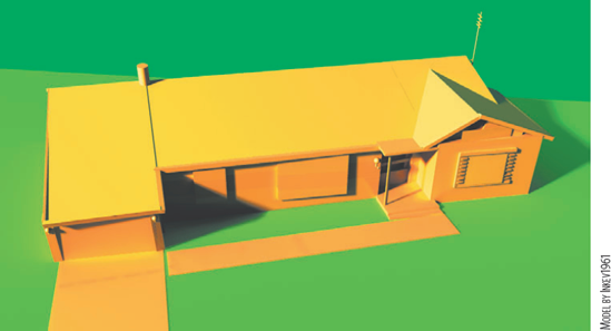
Figure 12.19. Mia_physicalsky and Mia_physicalsun shaders provide physically accurate outdoor lighting. A simplified version of this scene is included on the CD as physical_sky.ma.
The mental ray renderer provides six environment shaders. You can map each shader to the Environment Shader attribute of the rendering camera. They function in a manner similar to Maya environment textures. For example, Mib_lookup_spherical creates an infinite sphere to which a texture can be mapped. The mapped texture appears in reflections and refractions (assuming the reflective/refractive surface is not surrounded by other surfaces). Although the texture appears in the background of the render, it is not present in the alpha channel. In this way, Mib_lookup_spherical functions like the Env Sphere texture. Mib_lookup_spherical, however, cannot be mapped with a Maya texture. Instead, you must map the shader's Texture attribute with a mentalrayTexture node. In fact, when you click the checkered Map button beside the Texture attribute, a mentalrayTexture node is connected automatically. You can then choose a bitmap file by clicking the mentalrayTexture node's Image Name attribute Browse button.
Mib_lookup_cube6 is equivalent to Env Cube. Mib_lookup_cube1 uses a cube projection, but wraps a single texture around the six walls. Mib_lookup_cylindrical is a cylindrical variation. Mib_lookup_background fits a texture to the camera view on a virtual plane. Mia_envblur, available with Maya 2008, is designed to blur other environment shaders. For example, Mia_envblur is mapped to the Environment Shader attribute of a camera. In turn, Mib_lookup_spherical is mapped to the Environment attribute of Mia_envblur. The result is a blurred environment texture that appears in reflections (see Figure 12.20).
Mib_volume and Parti_volume shaders create a volume fog effect within a closed surface. You can find both shaders in the Volumetric Materials section of the Create mental ray Nodes menu. To apply either shader, you must map it to the Volume Shader attribute of the shading group node assigned to a surface. If the shading group node is also connected to a Maya material through the Surface Material attribute, the Transparency value of the Maya material must be increased for the volume material to be seen.
Mib_volume is an extremely simple fog that carries two attributes: Color and Max. Color represents the color of the fog and Max controls the density. A Max value of 0 will equal 100 percent density. A Max value greater than 8 will create close to 0 percent density.
Parti_volume is a more advanced material that supplies additional attributes to control light scattering and nonuniformity.
If a mental ray shader is used with Global Illumination or caustics, it will be ignored by the photon tracing process unless a connection is made to the Photon Shader attribute of the shading group to which the shader belongs. Maya 8.5 and Maya 2008 treat this necessity in slightly different ways.
With version 2008, some mental ray shaders, such as Dgs_material and Transmat, are automatically connected to both the Material Shader and Photon Shader attributes of a shading group node when they are created. Other shaders, such as those with the "Mib" prefix, are only connected to the Material Shader. With version 8.5, all shaders are connected to the Material Shader attribute, leaving Photon Shader open. In fact, mental ray provides four "sister" photonic shaders that may be used in this situation: Dgs_material_photon, Dielectric_material_photon, Transmat_photon, and Parti_volume_photon. Each corresponds directly to its material or volumetric material namesake. For example, if you want to photon trace with Dielectric_material, you can map Dielectric_material_photon to the Photon Shader attribute of the shading group node (see Figure 12.21). Dgs_material_photon, Dielectric_material_photon, and Transmat_photon are located in the Photonic Materials section of the Create mental ray Nodes menu. Parti_volume_photon is located in the Photon Volumetric Materials section.
Whether a sister photonic shader or a standard shader is mapped to the Photon Shader attribute of the shading group, it is important to match input attributes. That is, the attributes fed to Material Shader and Photon Shader should match. For example, if Dgs_material has a Shiny value of 50 and is mapped to Material Shader, then Dgs_material_photon should have a Shiny value of 50 as it is mapped to Photon Shader.
The mental ray renderer also provides a generic photon shader, Mib_photon_basic, which functions when paired with Dgs_material, Dielectric_material, and various "Mib" materials. Although this pairing cannot provide matched sets of attributes, Mib_photon_basic works well for simple Global Illumination renders.
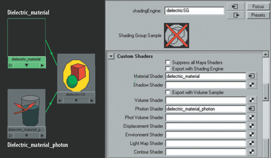
Figure 12.21. Dielectric_material and Dielectric_material_photon materials connected to a shading group node
Two additional attributes are provided by mental ray for rendering volume materials: Accuracy and Radius. These attributes are found in the Photon Volume subsection of the Caustics And Global Illumination section of the mental ray tab in the Render Settings window. You can use these attributes to control photon tracing with Mib_volume and Parti_volume materials. Descriptions of each follow:
- Accuracy
Sets the maximum number of neighboring photon hits included in the color estimate of a single photon hit. The higher the value, the more refined the render. (This attribute is named Photon Volume Accuracy in version 8.5.)
- Radius
Controls the maximum distance from a photon hit that the renderer will seek out neighboring photon hits to determine the color of the hit in question. The default value of 0 allows Maya to automatically pick a radius based on the scene size. (This attribute is named Photon Volume Radius in version 8.5.)
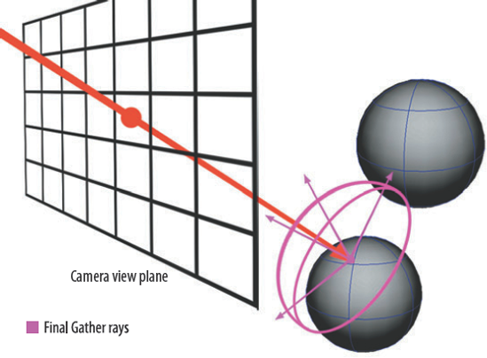
Although Final Gather is often used in conjunction with Global Illumination, it is not the same system. Final Gather employs a specialized variation of raytracing in which each camera eye ray intersection creates sets of Final Gather rays. The Final Gather rays are sent out in a random direction within a hemisphere (see Figure 12.22). When a Final Gather ray intersects a new surface, the light energy of the newly intersected point and its potential contribution to the surface intersected by the camera eye ray are noted. The net sum of Final Gather ray intersections stemming from a single camera eye ray intersection is referred to as a Final Gather point. The Final Gather points are stored in a Final Gather map and are eventually added to the direct illumination color calculations. The end result is a render that is able to include bounced light and color bleed.
During a render, the creation of Final Gather points occurs in two stages. During the first stage, which is precomputational, camera eye rays are projected in a hexagonal pattern from the camera view. Wherever a camera eye ray intersects a surface, a Final Gather point is created. In the second stage, which occurs during the visible render, additional Final Gather points are generated whenever the point density is discovered to be insufficient to calculate a particular pixel.
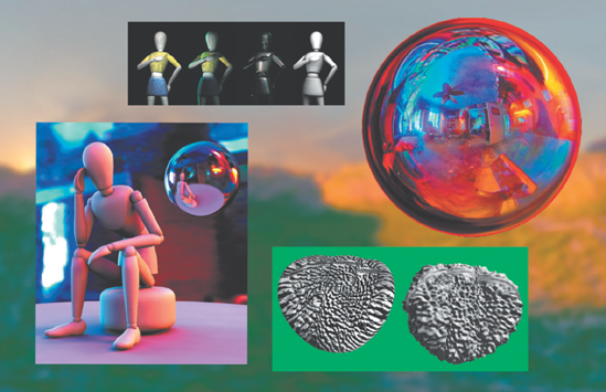
Ultimately, Final Gather is an efficient alternative to Global Illumination. Final Gather is particularly well suited for scenes in which diffuse lighting is desirable. For example, in Figure 12.23 a character is lit with a single spot light from frame right. The Maya Software render of the scene produces dark shadows. The Final Gather render, however, brightens the dark areas with "bounced" light. In addition, the yellow of the wall and the red of the stage spotlight "bleed" onto the character's hair, cheek, and torso.
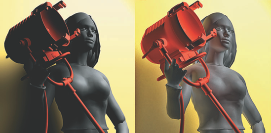
Figure 12.23. (Left) Scene rendered with the Maya Software renderer. (Right) Same scene rendered with mental ray Final Gather.
For the Final Gather system to work, the Raytracing and Final Gathering attributes must be checked in the Secondary Effects subsection of the Rendering Features section of the mental ray tab. In addition, Final Gather has a number of unique attributes in the Final Gathering section (see Figure 12.24).
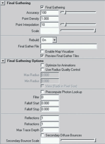
- Accuracy
Sets the number of Final Gather rays fired off at each camera eye ray intersection. Decreasing this value will shorten the render but will introduce noise and other artifacts. Values less than 200 will work for most test renders, while the maximum of 1024 is designed for final renders. This attribute is named Final Gather Rays in earlier versions.
- Point Density
Serves as a multiplier for the density of the projected hexagonal grid created during the pre-render stage. Values between 1 and 2 generally suffice. Higher values increase the amount of detail.
- Point Interpolation
Sets the number of Final Gather points that are required to shade any given pixel. Higher values produce smoother results.
- Scale
Serves as a multiplier for the Final Gather contribution to the render. You can tint the contribution by choosing a nonwhite color.
- Rebuild and Final Gather File
If Rebuild is set to On, a new Final Gather map is computed for each rendered frame. If Rebuild is set to Off, the renderer will use the preexisting Final Gather map listed in the Final Gather File attribute field. The map file is stored in the
Project_Directory/renderData/mentalray/finalgMap/folder. If Rebuild is set to Freeze, the renderer will rely on the Final Gather map calculated for the first frame of an animation and will not update the map as the animation progresses.- Enable Map Visualizer
Creates a mapViz and mapVizShape node when a Final Gather frame is rendered. You can view the map listed in the Final Gather File attribute field with the mental ray Map Visualizer (see "Reviewing Photon Hits" earlier in this chapter). Final Gather points are displayed as dots in the workspace view. Point Size and Normal Scale attributes in the Map Visualizer window control the size of the dots and their corresponding surface normals.
The following attributes are found in the Final Gathering Options subsection:
- Optimize For Animations
If checked, averages Final Gather points across multiple frames. This option reduces the flickering sometimes present with Final Gather renders.
- Use Radius Quality Control, Min Radius, and Max Radius
If Use Radius Quality Control is checked, Min Radius and Max Radius become available. Min Radius and Max Radius define the region in which Final Gather points are averaged to determine the color of a pixel. If an insufficient number of points are discovered within a region, additional points are created during the render for that region. (The number of required points is determined by the Point Interpolation attribute.) Maya's documentation suggests that the Max Radius should be no larger than 10 percent of the scene's bounding box. Along those lines, the Min Radius should be no more than 10 percent of the Max Radius. If a scene involves intricate or convoluted geometry, however, you can decrease the Min Radius and Max Radius to improve quality. The default value of 0 for both attributes allows Maya to select a Min Radius and Max Radius based on the scene bounding box.
- View (Radii In Pixel Size)
Forces the Min Radius and Max Radius attributes to operate in screen pixel size. The attribute offers an intuitive alternative to the measurement of the scene in world space.
- Precompute Photon Lookup
Turns on special photon tracing. In a prerender process, a photon map is created with an estimate of local energies in the scene. The map is used to reduce the number of needed Final Gather points. This attribute will slow the prerender but will speed up the actual render.
- Filter
Controls a special filter that eliminates or reduces speckles created by skewed Final Gather samples. If a surface in a scene is brightly lit, it can unduly influence energy calculations when intersected by Final Gather rays. A value of 0 turns the filter off. Values between 1 and 4 will soften the render somewhat but will reduce artifacts.
- Falloff Start and Falloff Stop
Define the world distance from a camera eye ray intersection that Final Gather rays are allowed to travel. Thus, these attributes determine the size of the hemispherical region associated with a Final Gather point (see Figure 12.22 earlier in this chapter). If a Final Gather ray reaches the Falloff Stop distance before intersecting a new surface, the contribution of the ray is derived from the camera's Background Color attribute.
- Max Trace Depth
Sets the number of subrays created when a Final Gather ray intersects a reflective or refractive surface. A default value of 0 kills the Final Gather ray as soon as it intersects a surface (although the energy contribution from that intersection is noted). A value of 1 allows a Final Gather ray to generate one additional reflection or refraction subray. Since Final Gather rays are simply searching for surfaces that might contribute light energy, the Max Trace Depth attribute can be left at 1 or 0 with satisfactory results for most renders.
- Reflections and Refractions
Respectively set the number of reflection and refraction subrays created when a Final Gather ray intersects a reflective or refractive surface. These attributes are overridden by the Max Trace Depth attribute, which controls the total number of subrays permitted per ray intersection. Reflections and Refractions were previously named Trace Reflections and Trace Refractions.
- Secondary Diffuse Bounces
When checked, allows indirect diffuse lighting to influence Final Gather points. This attribute is useful for adding light to dark corners or simply increasing the amount of color bleed. Secondary Diffuse Bounces will slow the render significantly. The Secondary Bounce Scale attribute serves as a multiplier for the indirect diffuse lighting intensity.
Final Gather does not require lights to render a scene. The system can use irradiance alone. Technically speaking, irradiance is a measure of the rate of flow of electromagnetic energy, such as light, from a per-unit area of a surface. The Ambient Color and Incandescence attributes of standard Maya materials represent irradiance.
For example, in Figure 12.25 a scene is rendered with Final Gather. The Enable Default Light attribute is unchecked in the Render Options section of the Common tab of the Render Settings window. A Fractal texture with an orange Color Gain attribute is mapped to a Blinn's Incandescence attribute, which provides the only light for the scene. Although the ground plane is assigned to a second Blinn material with Ambient Color and Incandescence values set to 0, it reflects the orange energy.
In addition, standard Maya materials carry Irradiance and Irradiance Color attributes in the mental ray section of their Attribute Editor tab. If the Irradiance attribute is mapped, the map becomes an irradiant light source. Irradiance Color serves as a multiplier for the resulting irradiant light.
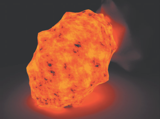
Figure 12.25. A primitive object lights a scene with orange irradiance. This scene is included on the CD as irradiance.ma.
You can view irradiant Final Gather points, as well as Final Gather points in general, through the mental ray Map Visualizer window. If a valid Final Gather map is listed in the Map File Name field, the points are automatically displayed in the workspace view as colored dots. The Point Size attribute controls the size. Search Radius Scale controls the density of displayed points; in most cases, it is not necessary to adjust this attribute.
Although there are no hard and fast rules regarding the simultaneous use of Global Illumination, Final Gather, and caustics, the incremental application of each will make the process less painful. If time limitations prevent the proper application of the Global Illumination process, you can simulate indirect illumination with Maya volume lights and the Maya Software renderer.
To demonstrate Global Illumination, Final Gather, and caustics, we'll use a variation of the famous Cornell Box (created at the Cornell University Program of Computer Graphics in 1984 to test physical-based lighting techniques). This particular box contains two point lights (see Figure 12.26). The Intensity attributes of the lights are left at 1. The floating C shape is assigned to a transparent Blinn with a Refractive Index set to 1.5. The camera's Background Color attribute is set to light red.
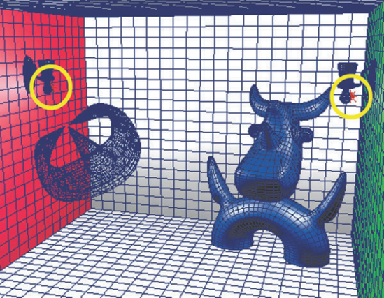
Figure 12.26. A Cornell Box. Yellow circles indicate the positions of two point lights. This scene is included on the CD as box_start.ma.
In the first step of the process, the Render Using attribute of the Render Settings window is switched to mental ray. The Quality Presets attribute is changed to Preview: Global Illumination, which checks on the Global Illumination and Ray Tracing attributes. Emit Photons is checked for each light. The lights produce the default 10,000 photons with a default Photon Intensity of 8000. The resulting render has visible photon hits. In addition, the white walls are a dingy gray (see Figure 12.27).
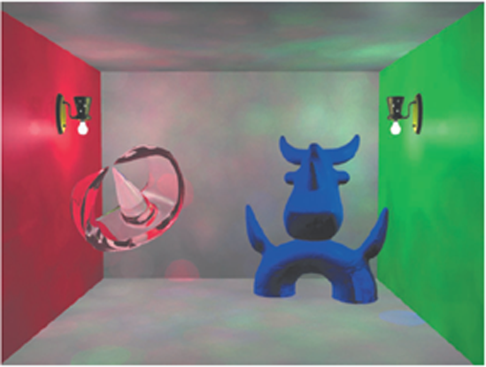
Figure 12.27. The Cornell Box is rendered with preview-quality Global Illumination settings. This scene is included on the CD as box_step1.ma.
Since the scene is 10 units high, we'll change the Radius attribute (found in the Global Illumination Options subsection) to 5. (To derive an appropriate value, we'll use the formula listed in the "Adjusting Global Illumination Attributes" section earlier in this chapter.) Since the scene is a bit dim, we'll raise each point light's Intensity to 1.25. The resulting render is significantly smoother (see Figure 12.28).
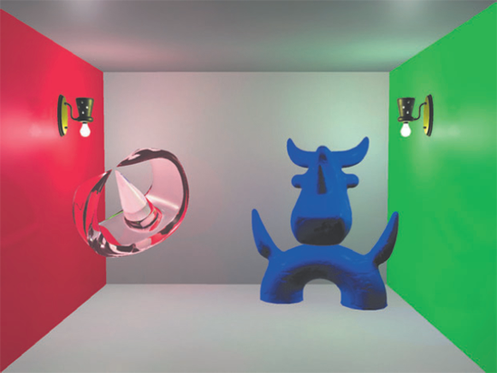
Figure 12.28. The Radius attribute in the Global Illumination Options section is changed to 5. This scene is included on the CD as box_step2.ma.
To increase the realism of the glass C-shape object, we'll adjust the Raytracing section of the mental ray tab. We'll change Reflections to 4, Refractions to 4, and Max Trace Depth to 6; this will allow light to bounce around the scene for a greater length of time. To create a caustic hot spot beside the C-shape, we'll check the Caustics attribute in the Caustics And Global Illumination section of the mental ray tab.
To create a more believable connection between the blue abstract shape and the floor, we'll check the Use Ray Trace Shadows attribute for each light. Although many Cornell Box simulations rely on indirect lighting to create dark areas, raytraced shadows adds an extra level of realism with minimal effort. To make the shadows acceptably soft, we'll set the lights' Light Radius to 2, Shadow Rays to 40, and the Ray Depth Limit to 10. In the resulting render, the blue shape gains a solid contact shadow (see Figure 12.29). A caustic hot spot also appears below the C-shape; unfortunately, individual caustic photons hits are visible.

Figure 12.29. The Cornell box receives caustics and raytraced shadows. This scene is included on the CD as box_step3.ma.
To improve the overall quality of the Global Illumination, we'll raise the Global Illum Photons of each light to 25,000. Since there are more photons in the scene, we'll reduce the Radius (in the Global Illumination Options subsection of the Render Settings window) by half (giving us a value of 2.5). We'll also raise the Caustic Photons of each light to 25,000. We'll change the Radius (in the Caustics Options subsection) to 2.5, thus matching the Global Illum Photons. As for other Render Settings window attributes, we'll switch Caustic Filter Type to Cone, Accuracy (directly below the Global Illumination check box) to 1000, and Accuracy (directly below the Caustics check box) to 500. The resulting render shows a significant improvement in the quality of the caustic. However, there are still a few errant caustic photon hits the near the C-shape (see Figure 12.30).
To smooth out the few remaining photon hits, we'll check Final Gathering in the Secondary Effects subsection of the Rendering Features section of the mental ray tab and leave the Final Gathering attributes at the default values. The resulting render is now clean enough to call final (see Figure 12.31).
The Final Gather process thoroughly blends the photon hits. In some situations, Final Gather can make the color bleed extremely subtle. For example, in Figure 12.31 the red and green bleed on the white wall is so faint that it can barely be detected. Nevertheless, the result, particularly around the blue shape, is convincing.
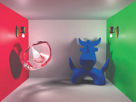
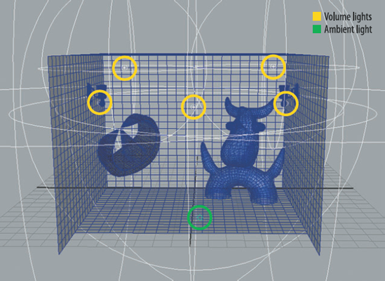
You can replicate indirect lighting and the mental ray Global Illumination system with Maya volume and ambient lights. Although the result is not perfect, the render is often close enough to meet the aesthetic demand of a project that is on a tight deadline. For example, in Figure 12.32 the Cornell Box is rendered with the Maya Software renderer with Raytracing checked. The overall lighting is similar to the one rendered with Global Illumination and Final Gather (see Figure 12.31).
To achieve this, five volume lights and one ambient light are placed in the scene (see Figure 12.33). Two large volume lights are placed next to the wall lamps. Their Intensity is set to 2. Two smaller volume lights are placed near the ceiling. Their Intensity is set to 0.2 and their Color attributes are set to red and green. These lights create a false color bleed. One last volume light is placed in the center of the box with an Intensity of 0.2. This volume light creates a soft fill. Volume lights, by their very nature, have a built-in falloff, which is easily adjusted by scaling the light shape up or down. To fill in the underside of the blue shape, an ambient light is placed near the floor with an Intensity of 0.175.

The one area in which this technique most noticeably fails is the caustic of the C-shape. The shape's shadow against the left wall is particularly inaccurate. Nevertheless, if caustics are not a critical part of a scene, you can use a similar setup to achieve refined results.
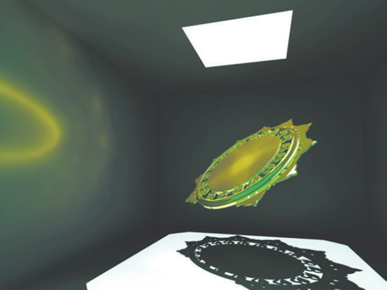
In this section, you will light and render a still life with Final Gather. You will also create a reflective caustic on one of the walls (see Figure 12.34).
Open
sun_box.mafrom the Chapter 12 scene folder on the CD. The scene features a variation of the Cornell Box with three walls and skylight hole. In this exercise, all the walls are gray. The floating sun symbol will become reflective metal.Create a spot light and place it directly above the skylight opening. Point the light down so it's perpendicular to the ground. Open the light's Attribute Editor tab. Check Use Depth Map Shadows and change Resolution to 1024. Set the Intensity attribute to 1.5. Check Emit Photons in the Caustic And Global Illumination subsection.
Open the Render Settings window. Switch the Render Using attribute to mental ray. Switch Quality Presets to Preview: Final Gather. Change Accuracy (directly below the Final Gathering check box) to 32.
Render a test frame. Keep the resolution low at this point. The spot light should strike the sun symbol. Adjust the position of the spot light until it makes an interesting shadow within the box.
Open the Render Settings window. Check the Caustics attribute in the Caustics And Global Illumination section. Global Illumination is not required to create the caustics. Increase Accuracy (directly below the Final Gathering check box) to 128. It's generally better to increase the various quality settings slowly over multiple test renders.
Render a test frame. A yellow caustic should appear on the left wall. Experiment with the placement of the sun symbol to create different caustic patterns.
Open the persp camera's Attribute Editor tab. Change the Background Color attribute (in the Environment section) to sky blue. The blue will show up in the sun symbol's reflections. Plus, the color will influence the Final Gather calculations and will ultimately tint the walls. Try different background colors to see what looks the best. Open the spot light's Attribute Editor tab and try different Color values.
Open the Render Settings window. Change Accuracy (directly below to the Caustics check box) to 128. Change Accuracy (directly below the Final Gathering check box) to 512. Change Radius, in the Caustics Options subsection, to 0.75. Open the spot light's Attribute Editor tab and incrementally raise Caustic Photons to 50,000. Render a series of tests. Experiment with different (Caustic) Radius and Caustic Photons values. Pick the combination that provides the best-looking caustic.
Once you're satisfied with the settings discussed thus far, raise the render resolution to 640 × 480 and the Min Sample Level and Max Sample Level attributes to 0 and 2 respectively. Continue to increase the Accuracy for both Caustics and Final Gather until the walls look smooth. The tutorial is complete! If you'd like to view a final version, open
sun_final.mafrom the Chapter 12 scene folder on the CD.