Shadows are an inescapable part of the physical world. Unless an animation is intended for a stylized look, high-quality shadows are a necessity for a professional render. Depth map and raytrace shadows can be fine-tuned to match many lighting scenarios. In addition, you can shadow advanced effects in Maya, including Light Fog, Maya Fur, Paint Effects, Maya Hair, nCloth, and the Toon system. To make the shadow-rendering process more efficient, you can link shadows.
Chapter Contents
Depth map methodology
Fine-tuning and troubleshooting depth maps
Adjusting raytrace shadows
Linking and unlinking shadows
Applying shadows to Light Fog
Creating shadows with Paint Effects
Creating shadows with Maya Fur and Hair System
Using shadows with nCloth and the Toon system
Depth maps are easy to apply and efficient to render. Unfortunately, their default quality is generally poor. You can improve the quality by adjusting various attributes and applying specific lighting strategies.
When the Use Depth Map Shadows attribute is checked for a spot, directional, point, area, or volume light, Maya creates a temporary depth map (see Figure 3.1).

The depth map represents the distance between surfaces in the scene and the shadow-casting light from the light's point-of-view. This information is stored as a monochromatic Z-depth buffer (see Figure 3.2). Objects far from the light receive dark pixels, and objects closer to the light receive light pixels.

When a surface point is rendered, its distance to the shadowing light is compared to the distance encoded in the corresponding depth map pixel. If the distance is greater than that encoded in the depth map pixel, it's assumed that another surface occludes the surface point's view of the light and the surface point is therefore shadowed. For example, in Figure 3.2 a distant building is partially occluded by a pair of gas pumps. The gas pumps are assigned brighter pixels because they are fairly close to the light. The part of the building that's not occluded has fairly dark pixels. Since the distance value of the dark pixels is equal to the actual distance that the surface points are from the light, no shadows occur in that area (with the exception of self-shadowing, which is discussed later in this section).
By default, depth maps are temporarily written to disk during a render but are not saved. You can force Maya to save the depth map as a Maya IFF bitmap, however, by switching the Disk Based Dmaps attribute (found in the shadow-casting light's Attribute Editor tab) from Off to one of the two following options:
- Reuse Existing Dmap(s)
With this option, the first time a frame is rendered, the depth map is written to the project folder with a name established by the Shadow Map File Name field (see Figure 3.3). (This attribute is called dmapName in version 8.5.) You can automatically add suffixes to the map name by checking the Add Scene Name and Add Light Name attributes. Each subsequent time the same frame is rendered, the written depth map is retrieved. This option is appropriate if the light position does not change between renders. You can change light attributes, such as Intensity, and material attributes (with the exception of displacement maps) between renders with no penalty. In addition, cameras can be repositioned.
If you batch-render an animation, the Reuse Existing Dmaps(s) option will render only the depth map for the first frame and apply it to all the frames. This is appropriate if objects are static (however, you can animate the camera). If objects are in motion, and their motion does not change between batch renders, check the Add Frame Ext attribute. Add Frame Ext adds a frame number to the depth map filename. The first time the animation is rendered, a depth map is rendered for each frame. For each subsequent render, the series of depth maps is retrieved and reused.
- Overwrite Existing Dmap(s)
This option assumes that a depth map has been written out at least one time. The new depth map is written over the old one with the name set by the Shadow Map File Name attribute. This option allows you to destroy old depth maps without seeking out the actual files.

By default, Maya writes out at least two IFF files per depth map per frame. The following naming convention is used:
ShadowMapFileName_lightName_sceneName.SM.iffframeNumberShadowMapFileName_lightName_sceneName.MIDMAP.SM.iffframeNumber
When a depth map is calculated, Maya shoots a shadow ray from the light view plane through each pixel of the depth map. The first surface point that the ray encounters is recorded in the SM map. The MIDMAP.SM map is created by the Use Mid Dist attribute.
Note
The depth map scene name suffix used by the batch render process differs from the scene name suffix used by the Render View window. The batch render uses the temporary scene file name, such as shadowtest__1740, whereas the Render View uses the letters int. Maya writes temporary scene files to disk with every batch render, even when no depth map shadows are present. This difference in suffix names can confuse the Reuse Existing Dmap(s) and Overwrite Existing Dmap(s) options.
By default, Use Mid Dist is checked for each light type that supports depth map shadows. This attribute significantly reduces self-shadowing artifacts, which often appear as bands across flat surfaces or a degradation of the shadow as it wraps around a curved surface (see Figure 3.4).

The artifacts are generally caused by one of two reasons:
Surface points are misinterpreted as existing "below" or "behind" adjacent surface points. This can occur when surface points are sampled within the boundary of a depth map pixel and are discovered to be farther from the light than the distance value encoded in that pixel (see Figure 3.5). Since the distance value stored in a depth map pixel is based on a single sample—one taken at the point which the shadow ray intersects the surface—this problem occurs frequently.
The pixels of a depth map, which may cover relatively large surface areas, are unable to accurately sample areas of high curvature. In such a case, surface points are incorrectly considered "behind" or "below" adjacent surface points.

In either of these situations, the artifacts are not visible in the depth map bitmap itself. The artifacts occur only during the render of the final image. As a solution, you can increase the depth map Resolution value. Unfortunately, this will reduce the size of the artifacts but will not necessarily eradicate them.
The Use Mid Dist attribute, on the other hand, artificially pushes the surface points closer to the light by comparing the distance from the light to the surface point and the distance from the light to a point halfway between the first surface encountered by the shadow ray and the second surface encountered (see Figure 3.6). The second surface encounters are recorded in the MIDMAP.SM depth map.
If a second surface is not encountered, the light's far clipping plane value is used. Again, the basic depth map algorithm works in the following manner:
If the distance between a surface point and the light is less than or equal to the distance encoded in the depth map pixel that contains the surface point in its boundary, the surface point is in light.
If the distance between a surface point and the light is greater than the distance encoded in the depth map pixel that contains the surface point in its boundary, the surface point is shadowed.
In this situation, Use Mid Dist forces the depth map to encode distances that are greater than the actual distance to the first surface encountered. Hence, surface points sampled during the render have a greater likelihood of possessing a smaller distance value when compared to the distance encoded in the corresponding depth map pixel.

Although Use Mid Dist is responsible for a huge improvement in the quality of the render, it cannot eliminate 100 percent of the artifacts. The Bias attribute, which operates on similar principles, is designed to work in conjunction with Use Mid Dist.
Bias holds true to its name and "biases" the surface points toward the light casting the shadow. Whereas Use Mid Dist forces the depth map to take its distance value from a point midway between the first encountered surface and the second, Bias simply multiplies the actual surface point position by a factor that transforms it closer to the light. For spot and point lights, the number entered into the Bias field is multiplied by the distance value derived from the depth map, the result of which is used to determine how far to offset the surface point in world space. Hence, large Bias numbers tend to make the shadow disappear or develop large holes. For directional lights, the Bias attribute is not multiplied by the depth map values but is used as is.
Trial and error is often the best solution when choosing a Bias value. When changing the value, incrementally step from 0.001 to 1. For example, in Figure 3.7 depth map artifacts appear along the edge of a convoluted surface. Although a 0.25 Bias value reduces the problem, a value of 0.5 removes the artifacts completely. Higher values erode the self-shadowing on the surface.
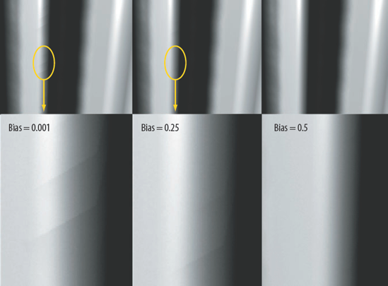
Figure 3.7. Depth map artifacts are eliminated by adjusting the Bias attribute. This scene is included on the CD as bias_values.ma.
With most scenarios, checking Use Mid Dist and leaving Bias at its default value is satisfactory for a scene. However, if you find it necessary to change the Bias value, proceed with caution. A Bias value that removes an artifact at one point on a surface can introduce an artifact at another point. For example, an incorrect Bias value will often "disconnect" a surface from a ground or floor. In Figure 3.8, a thin NURBS leg loses its connection with a plane.

If necessary, you can generate more than two depth maps per spot light. If a scene is large in world space or necessitates a large Resolution size, you can uncheck the Use Only Single Dmap attribute. When this attribute is unchecked, six additional attributes become available with the following naming convention: Use Axis+/– Map (see Figure 3.9).
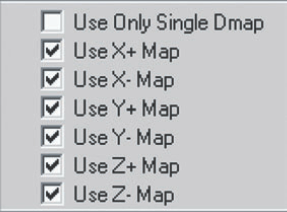
If one of these new attributes is checked, a depth map is rendered from the point of view of the light in one axis direction. For example, Use X+ Map writes a depth map aligned to the positive X axis. In this case, if Use Mid Dist is checked and Disk Based Dmaps is not set to Off, two depth maps are written out to the disk with the following names:
ShadowMapFileName.XP.iff
ShadowMapFileName.MIDMAP.XP.iff
P stands for positive axis direction. P is replaced by N if the axis direction is negative. The ability to choose direction is particularly useful for a spot light that must cover a large model. For example, in Figure 3.10 a spot light with a 120-degree Cone Angle value is placed close to the model of a building. Use X+ Map, Use X– Map, and Use Z– Map are checked. The resulting render creates two depth maps—one standard and one for Use Mid Dist—in each axis direction. If Use Only Single Dmap had been checked, the left and right sides of the model would have been excluded from the depth map. If the spot light were moved farther from the model to avoid this problem, a significantly larger Resolution would be required to maintain the map's detail.
By default, point lights create six standard depth maps and six corresponding depth maps for Use Mid Dist. These maps surround the point light in a virtual cube. You can turn off particular directions to save render time. For example, if no critical geometry exists below the point light, you can uncheck Use Y– Map. If a particular direction is completely empty, the corresponding depth map is ignored automatically.

You can view a depth map IFF file by choosing File > View Image and browsing for the filename. The FCheck window opens. Press the Z key while the mouse arrow is over the window or click the Z Buffer button. Since the depth information is stored in the Z channel of the IFF file, the depth map cannot be seen in Photoshop or other standard digital-imaging program. However, if you choose File > Save Image in FCheck while the depth map is visible, you can export the monochromatic image to any of the image formats supported by Maya. In this case, the information is written as RGB. Unfortunately, the converted file cannot be read by a Maya renderer because a depth map with an IFF extension and a Z channel is expected during the shadow-casting process.
Maya depth maps possess other attributes that are critical to the quality of their render. These include Resolution, Filter Size, Shadow Color, and Use Auto Focus. In addition, a specialized mental ray depth map and area light offers an alternative approach to creating shadows.
Resolution sets the pixel size of the depth map. Filter Size controls the amount of edge blur applied to the shadow. As a general rule of thumb, you can follow this guideline:
A crisp edge requires high Resolution and low Filter Size.
A soft edge requires low Resolution and high Filter Size.
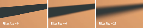
Aside from softening the shadow's edge, the Filter Size attribute is designed to disguise depth map limitations. Since depth maps are restricted by a fixed number of pixels, the pixels are often visible in the render. For example, in Figure 3.11 three different Filter Size values are applied to a depth map with its Resolution set to the default value of 512.
The blur created by Filter Size is applied to the shadow map equally at all edge points. Hence, it cannot replicate a diffuse shadow that changes edge quality over distance. You can overcome this limitation, however, by creating a custom shading network. For a demonstration of this, see Chapter 7.
Shadow Color tints the color of the shadow, thus emulating bounced light. Choosing a lighter color also creates a shadow that is less intense and gives the appearance that a greater amount of fill light is present.
The Use Auto Focus attribute automatically fits objects in the light's view to the resolution of the depth map. That is, if the objects are surrounded by empty space, the light view is "zoomed" in to maximize the number of pixels dedicated to the objects. Use Auto Focus is available on spot, directional, and point lights. Area and volume lights do not possess the attribute.
Note
If the cone of a spot light cuts objects out of the spot light's view, the Use Auto Focus attribute will not widen the view for the depth map. To avoid this problem, you will have to increase the light's Cone Angle, move the light backward, or manually set the light's Focus attribute.
In some situations, a scene will benefit if Use Auto Focus is unchecked and the light's Focus value is set manually. For example, if a depth map shadow is not critical for objects on the fringe of a scene, you can choose a Focus value that allows the light to concentrate on the scene's most important elements.
To choose an appropriate Focus value for a spot light, use the following steps:
Select the spot light and open its Attribute Editor tab. Uncheck Use Auto Focus. The Focus attribute becomes available.
With the light selected, choose Display > Rendering > Camera/Light Manipulator > Cone Angle. In a workspace view, choose Panels > Look Through Selected. The view through the light appears.
Click-drag the Cone Angle manipulator until the cone circle surrounds the objects in the scene that require a depth map shadow. Do not allow the cone circle to "split" a shadow-casting object in half; the resulting shadow will come to an abrupt stop in the render. Note the Cone Angle value and enter the number in the Focus attribute field. Move the manipulator back to its original position so that the original Cone Angle value is once again achieved.
Switch Disk Based Dmaps to Reuse Existing Dmap(s), enter a name into the Shadow Map File Name field, and render out a test frame. (This assumes that no depth maps have been written out.) Double-check the resulting depth map with FCheck. In the workspace view used to look through the light, choose an orthographic view through the Panels menu; this removes the temporary camera attached to the light by the Look Through Selected command.
Although directional lights possess the Focus attribute, choosing an appropriate value requires a different strategy. By default, directional lights possess direction but have no true position; despite the location of the light icon, they are considered to be an infinite distance from the subject. Hence, a directional light automatically includes all the objects in a scene for a depth map shadow. As a result, two new attributes become available when Use Auto Focus is unchecked: Width Focus and Use Light Position. Use the following steps to set these attributes:
Select the directional light and open its Attribute Editor tab. Uncheck Use Auto Focus and check Use Light Position.
In a workspace view, choose Panels > Look Through Selected. The view through the light appears. With Alt+RMB, dolly the light in or out so that the shadow-casting objects fill the view.
Using the workspace view menu, choose View > Camera Attribute Editor. In the camera's Attribute Editor tab, note the value in the Orthographic Width field in the Orthographic Views section. The Orthographic Width attribute represents the width of the visible scene as measured from the left side to the right side of the current view. Enter the value into the Width Focus field of the directional light.
Switch Disk Based Dmaps to Reuse Existing Dmap(s), enter a name into the Shadow Map File Name field, and render out a test frame. (This assumes that no depth maps have been written out.) Double-check the resulting depth map with FCheck. If the foreground appears clipped, the light icon is below, intersecting, or otherwise too close to the clipped surface. Simply dolly the light back in the workspace view and render another test. If shadow-casting objects are cut off at the left or right side of the depth map, gradually increase the Width Focus value and render additional tests.
The process of setting the focus for a point light is also unique. The point light Focus attribute does not correspond to either the Cone Angle or Orthographic Width attribute. You can determine an appropriate Focus value, however, by employing the following formula:
Focus = depth map world space width * 12
You can determine the world space width of a desired depth map by measuring across a scene with the Distance tool (choose Create > Measure Tools > Distance Tool). For example, in Figure 3.12 a desired depth map includes three center cones but not the outer two cones. The Distance tool is used to determine the maximum distance between the outer cones. The number, approximately 6.1, is multiplied by 12. The result is rounded off to 73 and entered into the Focus field. This formula represents a rough approximation. Multiple tests may be necessary to determine the best value.

The mental ray renderer supports standard Maya depth maps. In addition, mental ray can produce its own shadow map variation. You can also adapt a standard spot or area light by activating the mental ray area light options. (To render the mental ray light and shadow variations, switch the Render Using attribute, in the Render Settings window, to mental ray.)
When checked, the Use mental ray Shadow Map Overrides attribute (found in the Shadows subsection of the mental ray section of a spot, directional, area, or point light's Attribute Editor tab) overrides the standard Maya depth map shadow. (With Maya 8.5, you must uncheck the Derive From Maya attribute.) The Shadow Map Format attribute, found just above Use mental ray Shadow Map Overrides, controls the type of mental ray shadow map. The Regular Shadow Map option produces mental ray depth maps, which are more advanced than the Maya equivalent due to additional attributes. The Detail Shadow Map option supports object transparency and is discussed in Chapter 11. If you click the Take Settings From Maya button, the applicable values from the Depth Map Shadow Attributes section are transferred to the mental ray Shadow Map Overrides subsection. The following attributes control the look of the resulting mental ray shadow:
- Resolution
Sets the pixel size of the depth map.
- Samples
Sets the number of subpixel samples taken per pixel. Low values create grainy results.
- Softness
Controls the spread of the light. Values above 0 create a softer, more diffuse shadow edge. Higher values necessitate higher Samples values to create acceptable results (see Figure 3.13). High values tend to smear the shadow at surface corners.
- Bias
Functions in the same manner as the default Maya depth map Bias attribute by offsetting surface points to avoid self-shadowing artifacts. This attribute, if above 0, overrides the Shadow Map Bias attribute in the Shadow Map subsection of the Render Options section of the mental ray tab in the Render Settings window. Maya documentation recommends a Bias value that is less than the world distance between the light and the shadowed object. (Additional shadow attributes, including those found in the mental ray tab of the Render Settings window, are discussed in detail in Chapter 11.)
- Shadow Map File Name
When a name is entered into this field, mental ray shadow maps are written to disk in the
renderDatamentalrayshadowMapfolder within the project directory. The maps are overwritten with each new render. The depth map files are written in a native mental ray format and cannot be viewed with FCheck. Point lights automatically produce six depth map files, while other lights produce one each.

You can convert a spot light into a mental ray area light by checking the Area Light attribute (found in the Area Light subsection of the mental ray section of a spot light's Attribute Editor tab). You can convert a standard Maya area light into a mental ray area light by checking Use Light Shape (found in the same subsection). In both cases, mental ray adapts the chosen light by grafting a specialized mental ray area light onto the light icon (see Figure 3.14).
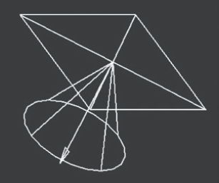
Figure 3.14. When the Area Light attribute is checked, a mental ray light is grafted onto the spot light icon.
The added area light acts as a light spread, thus creating a diffuse, soft-edged shadow. The result is most noticeable when combined with a default raytrace shadow, which produces a hard edge in its default state (see Figure 3.15).
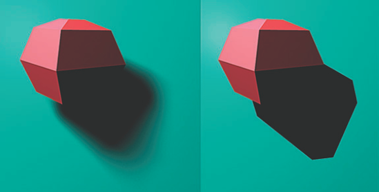
Figure 3.15. (Left) Raytrace shadow with a mental ray area light grafted onto a spot light. (Right) Default raytrace shadow with same spot light. This scene is included on the CD as area_spot.ma.
You can adjust the resulting shadow with the following attributes:
- Type
Determines the shape of the area light. Options include Rectangle, Disc, Sphere, Cylinder, and User. If Type is set to Cylinder, the area light sends shadow rays above, below, and behind the parent light. If Type is set to Sphere, the area light sends shadow rays in all directions. The User option allows you to apply a custom mental ray light shader to the area light.
- High Samples
Sets the number of shadow rays emitted from the area light, as measured in the X and Y direction of the light's icon. Default values leave the shadow very grainy. High values create an excellent result but slow the render.
- High Sample Limit
Represents the maximum number of times a shadow ray is permitted to reflect or refract before it must employ the Low Samples attribute. By switching to Low Samples, fewer shadow light rays are involved when calculating reflections and refractions.
- Low Samples
The number of shadow rays employed when the High Sample Limit is reached.
- Visible
If the parent light is a Maya area light, the Visible attribute determines whether the mental ray area light icon is visible in the render. If Visible is checked, Shape Intensity becomes available and controls the strength of the visibility. If Shape Intensity is set above 0, the icon renders as a solid white rectangle but does not affect the light striking surfaces in the scene. Maya documentation recommends using the mental ray area light in conjunction with the Maya area light as it requires lower sampling levels to produce higher-quality shadows.
Light gaps, which look like thin, bright lines, often appear along the intersection of two surfaces. For example, in Figure 3.16 two primitive planes sit at a right angle and intersect slightly. A spot light, placed behind the surfaces, casts a default depth map shadow. A light gap appears along the intersection seam. Such gaps are due to a mismatch of the depth map to the render of the geometry. Depth maps do not receive anti-aliasing, which leads to stair-stepping. (See Chapter 10 for information on render quality issues.) In this situation, the depth map will not accurately line up with the anti-aliased render, and the bright surface appears in the resulting "gap." The light's Filter Size attribute, which blurs the shadow edge, widens the gap if raised above 0.
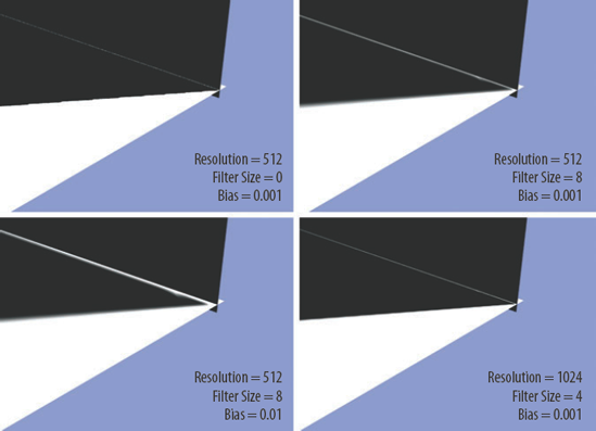
Figure 3.16. A light gap is visible at the intersection of two planes. This scene is included on the CD as light_gap.ma.
In this situation, higher Bias values make the error worse. You can increase the light's Resolution, which will reduce the strength of the light gap. However, the increased Resolution will not make the error disappear completely (see Figure 3.16). Switching to raytrace shadows will solve the problem but requires a more time-intensive render. Another solution involves the following steps:
Open the shadow-casting light's Attribute Editor tab. In the Depth Map Shadow Attributes section, set the shadow attributes to create a satisfactory shadow.
Switch Disk Based Dmaps to Reuse Existing Dmap(s). Enter a name into the Shadow Map File Name field. (This assumes that no depth maps have been written out.) Render a test frame. The render will write the depth maps to the project folder.
Select the vertical surface in a workspace view. Translate the surface away from the light. In the example illustrated in Figure 3.16, the plane needs to be translated only 0.2 units in the Z direction. When the plane is moved away from the light, the gap is covered by the geometry and is no longer visible in the render. The depth map is not updated since the Reuse Existing Dmaps(s) option retrieves the map after it has been written out the first time.
In another common depth map scenario, a shadow stops short of a hard corner on a surface. For example, in Figure 3.17 a tire-shaped polygon casts a depth map shadow onto a stand. The shadow stops short of the stand edge, producing a thin white line. In addition, a similar white line is visible along the inner edge of the tire that is in shadow. When the Filter Size is raised, the artifacts become worse. Once again, this problem arises from the mismatch of the aliased depth map with the anti-aliased final render. In this case, an increased Resolution value will reduce the intensity of the white lines.

Figure 3.17. Edge artifacts of two objects are reduced by increasing the depth map Resolution. This scene is included on the CD as depth_edge.ma.
Unfortunately, an increased Resolution cannot remove the artifacts along the surface edges completely. Raytrace shadows, on the other hand, do not produce this type of artifact.
Each light in Maya imparts distinctive qualities to the shadow it casts. Familiarity with the quirks and strengths of each light will help you make the proper decisions when lighting a scene. As a side-by-side comparison, each light type has been placed in an identical location on a test set (see Figure 3.18). A row of vertical cylinders illustrates the omnidirectional or multidirectional qualities of many of the lights.

All the lights, except for the ambient, cast depth map shadows with a Resolution set to 2048 and a Filter Size set to 2 (see Figure 3.19). The ambient light, which cannot cast depth map shadows, casts raytrace shadows with default setting. The area light casts both depth map and raytrace shadows since it possesses a unique, physical-based lighting method. The spot light is rendered with two cone sizes. All the lights, except for the volume, are left at their default scale. The volume light is scaled to surround the test set. The lights are turned on, one at a time, with the Illuminates By Default check box.
When the shadows of each light are compared, many qualities are identical; a few, however, stand out. In particular, the short shadows of the directional display the parallel quality of the light type. Even though the directional has the same Intensity value as all the other lights, it imparts the most illumination to the surface. In terms of realism, the area light with raytrace shadows is by far the best. Even though the raytrace attributes are left at their default settings, the area shadows become more diffuse with distance, mimicking light properties in the real world. In comparison, the area light with a depth map shadow creates a look similar to the volume light. Both the area and the volume have the most aggressive light decay.

Figure 3.19. The shadow qualities of Maya's six light types. This scene is included on the CD as light_set.ma.
Aside from the directional light, all the other lights have almost identical shadow patterns. In all these cases, if the light were moved farther from the cylinders, the shadows would become more parallel and less spread out. The spot light shows slight variations in the pattern when its Cone Angle is increased from 85 to 120. The directional and ambient lights provide the most even lighting, with the intensity of the surface changing little over its length and width. All the other lights create hot spots near the cylinders.
Raytrace shadows are more physically accurate than depth map shadows but are generally more processor intensive. Raytrace shadows represent the one type of shadow that is available to all light types, including ambient. For a raytrace shadow to be calculated, the Raytracing attribute must be checked in the Maya Software tab of the Render Settings window. When using the mental ray renderer, the Ray Tracing attribute must be checked. (For information on the raytracing process, see Chapter 11.)
Each light carries a set of raytrace shadow attributes:
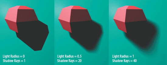
- Shadow Radius/Light Radius/Light Angle
Control the softness of the shadow edge by virtually scaling the size of the light (see Figure 3.20). Large light sources, such as a theater marquee or a window with sheer curtains, produce naturally diffuse, soft-edged shadows. Shadow Radius is provided for ambient lights. Light Radius is provided for spot, point, and volume lights. Light Angle is provided for directional lights. With each of these attributes, the larger the value, the softer the resulting shadow. Shadow Radius and Light Radius have a range from 0 to 1. Light Angle has a range from 0 to 360. Area lights do not possess any of these attributes; the softness of their shadows is determined by the position and rotation of the light icon.
- Shadow Rays
Sets the number of rays employed to calculate the shadow edge. The higher the value, the more refined the result.
- Ray Depth Limit
Sets the number of times a camera eye ray can reflect and/or refract and still cause reflected or refracted objects to cast raytrace shadows within the reflections or refractions. That is, higher values allow raytrace shadows to appear within a greater number of recursive reflections and refractions. If Ray Depth Limit is set to 1, no shadows appear in reflections or refractions.
You can find additional depth map and raytrace shadow attributes in the mental ray tab of the Render Settings window. These will be discussed in great detail in Chapter 11.
With Maya, you can make or break shadow links between lights and surfaces. If a shadow link is broken, the surface no longer casts a shadow for that light. For complex scenes, the ability to pick and choose which surfaces cast shadows can save render time and improve render quality.
By default, all surfaces cast shadows for shadow-producing lights that strike them. To break a shadow link for a surface while using the Maya Software or mental ray renderer, follow these steps:
If you are using Maya Software, open the Render Settings window, switch to the Maya Software tab, and expand the Render Options section. Change Shadow Linking to Shadows Obey Shadow Linking.
If you are using mental ray, open the Render Settings window, switch to the mental ray tab, and expand the Shadows section. Switch Shadow Linking to On.
Select the light and the surface whose shadow link you want to break. Switch to the Rendering menu set, and choose Lighting/Shading > Break Shadow Links. The surface will no longer cast a shadow for the selected light. To restore the shadow, select the surface and light and choose Lighting/Shading > Make Shadow Links.
Breaking a shadow link does not prevent a surface from receiving a shadow from another object. If Shadow Linking is set to Shadows Obey Light Linking (Maya Software) or Obeys Light Linking (mental ray), the surface will not cast a shadow only if it is unlinked from the light in the Relationship Editor or through the Break Light Links tool (see Chapter 2).
Note
To prevent a surface from casting a shadow for any and all lights, regardless of shadow linking, uncheck Casts Shadows in the Render Stats section of the surface's Attribute Editor tab. To prevent a surface from receiving shadows from all other surfaces, uncheck Receive Shadows.
Maya's Light Fog, Paint Effects, Fur, Hair, nCloth, and Toon systems create an amazing range of render effects. Although it is beyond the scope of this book to go into great detail for these effects, shadow creation for each is covered. Simple Paint Effects, Fur, Hair, nCloth, and Toon tutorials are included so that prior knowledge is not a prerequisite. (Light Fog is introduced in Chapter 2.)
Light Fog supports depth map shadows with the Maya Software renderer. More important, Light Fog will fail to interact properly with objects in a scene unless Use Depth Map Shadows is checked. Unfortunately, raytrace shadows and the mental ray renderer will not work with Light Fog. However, several mental ray shaders produce their own volume fog. (For more information, see Chapter 12.)
Two additional fog attributes, Fog Shadow Intensity and Fog Shadow Samples, are included in the Depth Map Shadow Attributes section of spot, point, and volume lights. Fog Shadow Intensity dictates the darkness of shadows appearing in the body of the fog (see Figure 3.21).
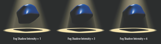
Figure 3.21. Light Fog shadow with three different Fog Shadow Intensity settings. This scene is included on the CD as fog_shadow.ma.
The higher the Fog Shadow Intensity value, the less fog remains in the shadowed area. A value of 10 generally removes all the fog in the shadowed area and leaves a clean alpha channel (assuming there are no objects behind the fog).
Fog Shadow Samples, on the other hand, reduces potential fog graininess by applying additional sampling. Although there is no built-in maximum for the attribute, the default value of 20 is generally sufficient for a smooth render.
Paint Effects is a powerful tool that allows you to interactively paint specialized strokes that create complex geometry as a post-process. Numerous Paint Effects brushes are included with Maya and are grouped in such categories as grasses, trees, fire, and fibers. To create a simple Paint Effects scene, you can follow these basic steps:
Create a primitive, such as a sphere. Select the primitive, switch to the Rendering menu set, and choose Paint Effects > Make Paintable.
Choose Paint Effects > Get Brush. The Visor window opens. Select a brush folder, such as trees. Select a brush style by clicking a Paint Effects icon. Close the Visor.
Click-drag the mouse arrow over the primitive. The Paint Effects stroke is laid over the surface, and the Paint Effects tube or sprite will grow from it.
Render a test with the Maya Software renderer. The Paint Effects brush is laid over the geometry at the end of the render. (Unfortunately, mental ray does not support Paint Effects.)
A Paint Effects stroke is a specialized set of nodes. The stroke shape and transform nodes generate the geometry visible in the workspace view. The hidden curve node controls the shape of the stroke path. If you select the curve node in the Hypergraph Hierarchy or Outliner window, you can scale, translate, and rotate it like any other curve. You can also manipulate or animate the vertices of the curve to change the shape. The stroke geometry automatically follows the curve. Curve-editing tools, however, cannot be applied to the curve node. If a Paint Effects brush is applied to a surface through Make Paintable, the stroke geometry automatically deforms and moves with the surface. You can apply Paint Effects brushes to any surface that has valid UVs. Last, the brush node, which carries all the brush attributes, is connected to the stroke shape node. You can view the brush node in the Hypergraph Connections window; in addition, the brush node appears beside the stroke shape node in the Attribute Editor. The brush node is named after the brush type (for example, rope1).
The majority of Paint Effects brushes grow special tube geometry as part of the post-process. This is most noticeable with brushes that create plant life. A long list of attributes controls the tube growth; these can be found in the Tubes section of the brush node's Attribute Editor tab. Tubes can generate excellent shadows. In contrast, a few Paint Effects brushes create sprites. With these brushes, a bitmap is applied to a flattened tube with alpha information. No matter what direction the camera points, the sprite bitmap always faces the camera. Although sprites can cast shadows, the results are rough.
Paint Effects strokes cannot cast raytrace shadows. However, two attributes are provided to create depth map and fake shadows. They can be found in the Shadow Effects section of the brush node's Attribute Editor tab (see Figure 3.22).

- Cast Shadows
If checked, the Paint Effects stroke is included in the depth map calculation. If the depth map's Resolution is sufficiently large, the result is quite accurate.
- Fake Shadow
Provides two methods by which to create shadows without using depth maps: 2D Offset and 3D Cast.
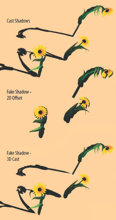
2D Offset creates a drop-shadow effect by replicating the shape of the stroke as viewed by the camera and offsetting it in screen space (see Figure 3.23). This is the least convincing shadow but may be suitable for dense strokes that lie close to a surface, such as eyebrow hair or short grass. 2D Offset will potentially reduce the render time of scenes with a large number of complex strokes. When Fake Shadow is switched to 2D Offset, the Shadow Diffusion, Shadow Offset, and Shadow Transp. attributes become available. Shadow Diffusion controls the softness of the shadow and affects the blending of individual tube shadows. Higher values produce slightly soft results but make the shadows more cohesive. Shadow Offset sets the distance that the shadow is offset. If Shadow Offset is 0.5, the fake shadow is approximately 50 percent visible. If Shadow Offset is above 1, the fake shadow is no longer rooted to the stroke. Positive Shadow Offset values move the fake shadow to the screen right of the stroke. Negative values move the fake shadow to the screen left of the stroke. Shadow Transp. determines the opacity of the shadow. Although you can use 2D Offset in conjunction with Cast Shadows, the results are generally better if Cast Shadows is unchecked. 2D Offset is the one style of shadow that works with sprite Paint Effects.
The 3D Cast option creates a shadow by defining an unseen, flat plane below the stroke and casting a shadow onto it. This option provides good results when the stroke itself is flat or is applied to a fairly smooth surface (see Figure 3.23). 3D Cast shadows are refined by the Shadow Diffusion and Shadow Transp. attributes. Although you can use 3D Cast in conjunction with Cast Shadows, the results are better if Cast Shadows is unchecked. Although 3D Cast shadows are relatively accurate, they have a tendency to separate from the root of the stroke.
In addition to shadow effects, Paint Effects strokes include several attributes to create self-shadowing:
- Back Shadow
Darkens Paint Effects tubes that are farthest from the light. The higher the value, the darker the result.
- Center Shadow
Darkens the tubes that are formed closest to the stroke path. The higher the value, the darker the result.
- Depth Shadow
Darkens the stroke tube along its length based on the distance from a tube point to the corresponding surface or stroke path. If Depth Shadow Type is set to SurfaceDepth, the distance is measured from the tube point to the surface on which the Paint Effects stroke is drawn. If Depth Shadow Type is set to PathDist, the distance is measured from the tube point to the nearest point on the stroke path. Depth Shadow Depth defines the maximum distance that the Depth Shadow shading effect is permitted to act within.
Note
Paint Effects brushes can be adapted or written from scratch. Each Paint Effects brush exists as a MEL text file in the brushes folder of the Maya program directory.
The Maya Fur system grows numerous hairs over a surface. You can use depth map shadows with fur if special attributes are added to a spot light. If the special attributes are added to other light types, self-shadowing is available. In addition, you can create raytrace fur shadows with the mental ray renderer.
To create a simple fur setup and cast depth map shadows, follow these steps:
Create a NURBS, polygon, or subdivision surface. Switch to the Rendering menu set and choose Fur > Attach Fur Description > New. (If you are running Maya Unlimited but do not see the Fur menu, check the
Fur.mllplug-in in the Plug-In Manager window.) The default fur appears on the surface. You can attach fur to any surface that has valid UVs. Create a primitive plane and place it under the surface so that shadows can be cast.Create a spot light for the surfaces and check Use Depth Map Shadows in the light's Attribute Editor tab.
With the light selected, choose Fur > Fur Shadowing Attributes > Add To Selected Light. Attributes are added to the Fur Shading/Shadowing section of the light's Attribute Editor tab (see Figure 3.24). Switch the Fur Shading Type attribute to Shadow Maps. Leave the Threshold attribute set to 0. Threshold is designed to eliminate the shadows of extra-fine hairs; a hair is only included in a pixel of a depth map if it covers a percentage of the pixel greater than the Threshold value.
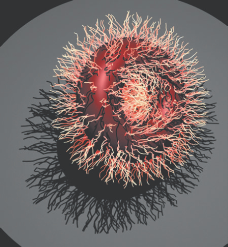
Render a test frame with the Maya Software renderer. The fur will create an appropriate shadow (see Figure 3.25). Open the Render Settings window and switch the Render Using attribute to mental ray. Render out a second test frame. The shadow continues to appear. If the shadow appears grainy with mental ray, check the Use mental ray Shadow Map Overrides attribute in the Shadows subsection of the light's Attribute Editor tab and adjust the attributes within the Shadow Map Overrides subsection. (See the section "Using mental ray Shadow Maps and Area Lights" earlier in this chapter.)

Maya Fur supports raytrace shadows only if the renderer is switched to mental ray. To see raytrace shadows, check Use Ray Trace Shadows in the light's Attribute Editor tab and switch the Quality Presets attribute to Draft or Production in the mental ray tab of the Render Settings window. (The default settings of the mental ray ProductionRapidFur preset are designed for depth map shadows and will not produce raytrace shadows.)
Note
Maya may incorrectly place fur shadows if Auto Focus is checked in the light's Attribute Editor tab. For best results, uncheck Auto Focus and enter a value into the Focus field. Maya documentation recommends that you derive the Focus value from this formula: Cone Angle + (Penumbra Angle × 2).
If Maya Software is the renderer of choice, Add To Selected Light must be applied to each spot light that is creating a shadow. You can remove the Fur Shading/Shadowing attributes of a light by selecting the light and choosing Fur > Fur Shadowing Attributes > Remove From Selected Light. If mental ray is the renderer of choice, Add To Selected Light is not needed. If the Fur Shading/Shadowing attributes already exist, mental ray ignores them. Whereas the Maya Software renderer creates the fur as a post-process, mental ray integrates the fur directly into the scene. In general, mental ray raytrace shadows are more accurate than Maya Software depth map shadows, which have a tendency to separate individual hair shadows from the hair bases. You can use any light type when raytracing fur shadows with mental ray. In addition, mental ray possesses the following render capabilities:
Fur appears in reflections and refractions.
Fur casts colored shadows.
Fur motion blurs.
If Fur Shading Type is switched to Auto Shading, self-shadowing attributes become available (see Figure 3.24 earlier in this chapter). Auto Shading is available to every light type except volume (which does not support fur shadowing). As with a spot light, the Fur Shading/Shadowing section must be added to the light by choosing Fur > Fur Shadowing Attributes > Add To Selected Light. The following attributes accompany Auto Shading:
- Self Shade
Defines the percentage of the fur hair length that is darkened. The percentage is anchored at the root. Thus, if Self Shade is 0.5, a fur hair is darkened from the root to its mid-length point. If Self Shade is 1, the entire hair is darkened. A value of 0 effectively turns the Self Shade attribute off. Self Shade Darkness controls the amount of black mixed with the fur hair's original color. A value of 0.5 will equally mix black with the fur hair color. A value of 1 will make the fur hair pure black.
- Back Shade Factor
Artificially darkens the fur hair that lies on the surface side opposite the light source. A Back Shade Factor value of 0 creates a harsh transition from the lit side of the fur to the dark side. Values between 0 and 1 create a more natural falloff from the lit side to the dark side. Values above 1 make the falloff more rapid. A value of 0 effectively turns the Back Shade Factor attribute off. Back Shade Darkness controls the amount of black mixed with the fur hair's original color. A value of 0.5 will equally mix black with the fur hair color.
- Intensity Multiplier
Serves as a multiplier for the light intensity read by the fur. Fur strongly reflects light and is thereby often rendered inappropriately bright. Reducing this attribute below 1 will darken the fur without affecting other objects in the scene. Intensity Multiplier functions even if Fur Shading Type is set to No Shading.
The Maya Hair system generates a series of dynamic curves that can simulate hair, ropes, chains, and other thin but long elements. The quickest way to generate hair in Maya is to switch to the Dynamics menu set, choose Hair > Get Hair Example, select a hair icon in the Visor window, right-click, and choose Import Maya File name of hair file from the shortcut menu. A complete scene with a polygon model and hair system is brought in. Otherwise, you can create a hair system from scratch following these steps:
Create a NURBS or polygon primitive. Choose Hair > Create Hair with default settings. A hair system is attached. You can attach hair to any NURBS or polygon surface that has valid UVs. If you would like to add hair to a specific location on the surface, choose Hair > Paint Hair Follicles >

Relax the hair by playing back the Timeline. Once the hair has fallen and has come close to rest, stop the playback. You can set the hair's current position as a new start position by selecting the hair curves and choosing Hair > Set Start Position > From Current. The hair will not collide with the surface unless you select the hair curves and the surface and choose Hair > Make Collide.
Create a light and check Use Depth Map Shadows. Render a test frame. A shadow appears across the surface. Open the Render Settings window and switch the Render Using attribute to mental ray. Render out a second test frame. The shadow continues to appear (see Figure 3.26). If the resulting mental ray shadow appears grainy, check the Use mental ray Shadow Map Overrides attribute in the Shadows subsection of the light's Attribute Editor tab and adjust the attributes within the Shadow Map Overrides subsection. (See "Using mental ray Shadow Maps and Area Lights" earlier in this chapter.)
When a hair system is created, many new nodes are included. The hairSystemFollicles node is a group node to which all the follicle shape nodes belong as children. Follicles are small, red circles along the hair-generating surface that create individual clumps of dynamic curves. The hair that is rendered is actually a Paint Effects tube. Hence, pfxHair, pfxHairShape, and hairSystemShape are included. pfxHair serves as a transform node for the hair system. pfxHairShape carries global Paint Effects attributes such as Display Quality. hairSystemShape carries a specialized set of Paint Effects attributes designed for rendering hair.

Figure 3.26. (Left) Maya Hair without shadows. (Right) Maya Hair with depth map shadows rendered with mental ray. This scene is included on the CD as hair.ma.
Note
A specialized material, Hair Tube Shader, is designed for a hair system that is converted from Paint Effects to polygons (you can choose Modify > Convert > Paint Effects To Polygons). The material is automatically assigned to the resulting polygons and includes specialized color gradients and specular controls designed specifically for human and animal hair. The material is unique in that it ignores surface normals and instead bases its shading on the camera view and Tube Direction attribute. Since the Hair Tube Shader material is a variation of the Anisotropic material, you can assign it to any surface. (For more information on Maya materials, see Chapter 4.)
You can render hair with raytrace shadows if the mental ray renderer is selected. Whereas the Maya Software renderer creates hair as a post-process, mental ray integrates the hair directly into the scene. As such, mental ray possesses the following render capabilities:
Hair appears in reflections and refractions.
Hair motion blurs.
You can turn on or off the hair's reflection visibility, refraction visibility, and the ability to receive shadows by checking the Visible In Reflections, Visible In Refractions, and Receive Shadows attributes in the Render Stats section of the hairSystemShape node's Attribute Editor tab.
With nCloth, Maya provides a robust dynamic simulation system with which you can realistically emulate cloth objects. nCloth adapts preexisting polygon surfaces. To create a simple scene with nCloth, follow these steps:
Create a polygon plane and position it above a polygon sphere.
Switch to the nCloth menu set (you must be running Maya Unlimited). Select the plane and choose nCloth > Create nCloth. The plane is tessellated and converted into an nCloth dynamic mesh. This is indicated by a small circle icon at the plane's center.
Return to frame 1 and play back the Timeline. At this point, the nCloth plane falls but fails to interact with the sphere. To prevent this, select the sphere and choose nCloth > Create Passive >
When the Create nCloth tool is applied, an nCloth shape node is created. The original polygon shape node is connected to the nCloth shape node and is used as an input mesh. Because the original polygon surface is not destroyed, it provides UV and other material information to the nCloth mesh. Therefore, you can render nCloth with standard materials and depth map or raytraced shadows (see Figure 3.27).

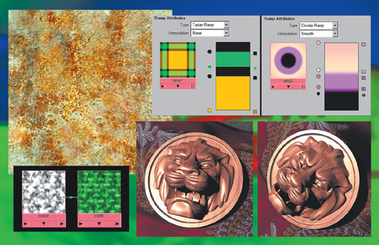
The Maya Toon system emulates the "ink and paint" method of traditional 2D cel animation. Solid "ink" outlines are applied to areas of solid-color "paint." The outlines are specialized tube geometry that is applied to the assigned surfaces. The areas of color are created by Surface Shader and Ramp Shader materials, which are assigned by the Toon system.
The quickest way to apply the Toon system is to switch to the Rendering menu set, choose Toon > Get Toon Example, select a Toon icon in the Visor window, right-click, and choose Import Maya File name of Toon file from the shortcut menu. A complete scene with a Toon system is brought in. Otherwise, you can apply the Toon system with the following steps:
Create several NURBS or polygon primitives. Allow them to partially intersect. Choose Toon > Assign Outline > Add New Toon Outline. Toon outline tubes are created and applied to all the outer edges and corners of the primitives.
At this point, the primitives remain assigned to the default Lambert material. To create the paint-like quality, select the primitives again and choose Toon > Assign Fill Shader > Solid Color. A Surface Shader material is automatically assigned to the primitives. You can change the Out Color attribute of the material to change the "paint" color.
Surface Shader materials ignore all lighting and shadowing information in a scene. Therefore, the Solid Color fill shader does not create shadows. However, if you choose Toon > Assign Fill Shader > Shaded Brightness Two Tone or Shaded Brightness Three Tone, shadows are generated. In this situation, a Ramp Shader is assigned to the surfaces. The Color Input of the Ramp Shader is set to Brightness, which forces Maya to apply the colors of the Ramp Shader's Color gradient based on the brightness of the surface. Shadowed surface areas, which receive little or no light, pick up the left-hand side of the gradient (see Figure 3.28). This works with both depth map and raytrace shadows. Although the mental ray renderer supports the Ramp Shader material, it does not render the Toon outlines. (For more information on the Ramp Shader material, see Chapter 7.)

Figure 3.28. A pair of primitives are assigned a Toon outline and the Shaded Brightness Two Tone fill shader. The render is raytraced. This scene is included on the CD as toon_shadow.ma.
Other Fill Shaders are accessible through Toon > Assign Fill Shader > name of shader. Light Angle Two Tone applies a Ramp Shader, but sets the Color Input attribute to Light Angle. The Light Angle option chooses colors from the gradient based on the angle between the surface normals and the illuminating lights. Oddly enough, Light Angle Two Tone generates shadows. Rim Light, on the other hand, uses a Ramp Shader material, but adds a white color handle to the Incandescence gradient and therefore creates a thin white line around the surface's edge. Circle Highlight is similar, but inserts a white handle into Specular Color gradient, thereby creating an artificial specular highlight on the brightest potion of the surface. Both Rim Light and Circle Highlight options generate shadows.
When the Add New Toon Outline tool is applied, a pfxToon transform and pfxToon shape node are created. The pfxToon shape node generates the tube geometry for the "ink" outline and hosts a long list of attributes that affect the outline position, color, and behavior.
In this tutorial, you will create a fire with soft, flickering shadows (see Figure 3.29). You will use Paint Effects fire with a volume, ambient, and directional light.

Figure 3.29. Fire created with a Paint Effects brush and lit with a directional, ambient, and volume light. A QuickTime movie is included on the CD as fire_pit.mov.
Note
Open the
fire.mafile from the Chapter 3 scene folder on the CD. Create a directional light. Open its Attribute Editor tab. Change the Color to a pale blue. This will serve as the scene's moonlight.Move the directional light above the set and to screen right. Rotate it toward the fire pit. Render out a test frame. Adjust the light's Intensity and Color until satisfactory. Although this light will not be the key light, the sand and rocks should be appropriately visible for nighttime.
In the directional light's Attribute Editor tab, check Use Depth Map Shadows. Set Resolution to 512 and Filter Size to 6. This combination of medium Resolution and moderate Filter Size will create a slightly soft shadow. Render a test frame. Experiment with different light positions and shadow settings.
Create an ambient light and open its Attribute Editor tab. Set the Intensity attribute to 0.2, or approximately 1/10th the Intensity value of the directional. Tint the ambient light's Color to pale blue. Move the ambient light to screen left, just above the set. This light serves as a low fill that will prevent the backside of the rocks from becoming too black.
Create a volume light and open its Attribute Editor tab. Change Light Shape to Cylinder. Change the Color to a deep orange. In the Penumbra section, click the left handle of the gradient. Once the handle is selected, change the Interpolation attribute to Smooth. This will change the linear gradient to one that has a slow start and a slow end; ultimately, this will make the falloff of the volume light more subtle.
Move the volume light to the center of the fire pit. Scale the light so that it is approximately twice the length, width, and height of the fire pit. In this case, the volume light will look oval from the top and short and squat from the side. Render a test frame to see how far the light from the volume light is traveling.
In the volume light's Attribute Editor tab, check Use Depth Map Shadows. Set Resolution to 128 and Filter Size to 6. This creates a soft shadow emanating from the center of the pit. Render out a test frame. The rocks should produce shadows similar to the shadows in Figure 3.29.
Select the cone-shaped ash geometry, which lies in the center of the fire pit. Choose Paint Effects > Make Paintable. Choose Paint Effects > Get Brush. The Visor window opens. In the Paint Effects tab, click the brush category folder named fire. Several fire brush icons become visible. Click the largeFlames icon. Close the Visor window. In the top view, click-drag the pencil mouse icon over the ash geometry. When the mouse button is released, a Paint Effects stroke is created. Keep the stroke fairly short.
Render out a test frame. Fire will appear where the stroke is drawn. Initially, the fire is too small to be seen over the top of the sticks and rocks. Select the stroke curve and open its Attribute Editor tab (which is labeled largeFlames1). Change the Global Scale attribute to 60. Render out a test frame. The flame should be clearly visible. If the flames appear too bright or saturated, adjust the stroke's Color1 and Color2 attributes (found in the Shading section of the stroke's Attribute Editor tab). In addition, you can darken the Glow Color (found in the Glow section of the stroke's Attribute Editor tab). Initially, the flames will move too slowly. To speed up the fire, change the Flow Speed attribute to 0.8. You can find Flow Speed in the Flow Animation section of the stroke's Attribute Editor tab.
Following the process detailed in steps 8 and 9, paint additional Paint Effects strokes on the ash geometry. Multiple strokes are necessary to make the fire convincing. Experiment with different fire styles with different scales. The version illustrated in Figure 3.29 uses three strokes and employs the following brushes: largeFlames and flameMed.
Paint Effects fire is preanimated and will automatically change scale and shape in a convincing manner. To match this animation, you can keyframe the Intensity, TranslateX, and TranslateZ of the volume light. To do this, move the Timeline slider to frame 1. Select the volume light. Set a key by pressing Crtl+S or choosing Animate > Set Key from the Animation menu set. A red key frame line will appear at frame 1 of the Timeline. Move the Timeline slider to frame 5. Translate the volume light slightly in the X or Z direction (no more than 1 world unit). Set another key. Repeat the process through the duration of the Timeline. You'll want to add keyframes every 3 to 12 frames in a random pattern (see Figure 3.30). In the end, the volume light should move back and forth in an unpredictable manner. This will cause the volume shadows to move over time in a fashion similar to actual flickering fire light.
To animate the volume light changing its Intensity over time, move the Timeline slider to a desired frame and right-click the Intensity field. In the shortcut menu, choose Set Key. For the duration of the Timeline, set Intensity keys every 3 to 12 frames. Randomly vary the Intensity from 2 to 3 (see Figure 3.30).
The fire pit is complete! Render out a low-resolution AVI as a test. The fire and corresponding light should flicker. If you get stuck, a finished version has been saved as
fire_finished.main the Chapter 3 scene folder on the CD.