
IN THIS CHAPTER
Local component patterns
Derived component patterns
Other pattern options
Tutorial: Creating component patterns
In SolidWorks assemblies, the word component can refer to either parts or subassemblies at the top level of an assembly. Component patterns can therefore be patterns of parts, subassemblies, or combinations of parts and subassemblies.
Note
For best pattern performance, you should use subassemblies as the patterned unit as much as is practical. Multiple patterns of individual components are not as efficient as a single pattern of multiple components. A single pattern of a single component, where the single component is itself a subassembly, is the best choice, if available.
Another performance issue is the fact that component patterns require external references (for the direction or center of the pattern). These external references have the potential to increase rebuild times if you do not choose them carefully.
Although you can experience possible performance problems with patterns, they can also significantly decrease the number of mates in an assembly, which always improves performance.
Component patterns come in two varieties: local patterns, which include linear and circular patterns, and derived patterns, which are driven from a feature pattern in a part. The local patterns are obviously somewhat limited, but because derived patterns follow patterned features, they can also be driven by sketch-driven patterns. Curve-driven and fill patterns cannot be used.
It is possible to focus only on the basics, to simply be able to make patterns that exist in the present moment. However, if you are interested in creating features that will adapt to future changes, then you will find this chapter useful.
Local component patterns are limited to linear and circular patterns. The linear pattern directions work just like the linear pattern feature in parts, and must reference a line, axis, edge, and so on to establish the direction. In an assembly, this means that the feature uses model geometry from a part (solid or surface edges, sketches, reference geometry), an assembly sketch entity, or an assembly reference geometry entity (such as an axis). This is important to keep in mind if you are concerned about circular references.
Note
If you have a feature pattern in a part, you should take advantage of it and use a driven pattern instead of a local pattern.
If you still need to create a local pattern, it is best to use a reference that is not dependent on part geometry. Remember that when part geometry is used for this purpose, the parts must be solved first (sketches and features rebuilt), then the mates must be solved (to position the parts), then any in-context references must be solved (which may change the part geometry), and then any assembly features or component patterns must be solved. As a result, it is best practice to use as pattern direction references, assembly sketches that do not reference anything else. The assembly sketches should sit at the top of the assembly FeatureManager to ensure that they are not picking up references from the history-based features in the design tree (mated components, patterns, assembly features, and so on).
When a local pattern really requires a reference from a part, you have no alternative. However, if you can avoid this by using a sketch assembly skeleton to which the parts are mated and also used for the pattern references, then you should do so. At all costs, you should avoid using in-context features, assembly reference geometry that is dependent on part geometry, and assembly features for the local pattern reference.
Figure 15.1 shows a sample organization of one way that you can set up an assembly to properly control local component patterns. The lines shown can be created in either two 2D sketches or a single 3D sketch. The lines are dimensioned from planes, which allows them to be angled for patterns that are not square to the coordinate system of the assembly, but still lie on its main planes.
In most situations the rebuild time penalty of using model geometry to establish pattern direction is fairly slight. The sketch method is probably most justifiable in large, complex, assemblies, or in assemblies requiring long rebuild times.
Figure 15.1 also shows the PropertyManager interface for the local pattern.
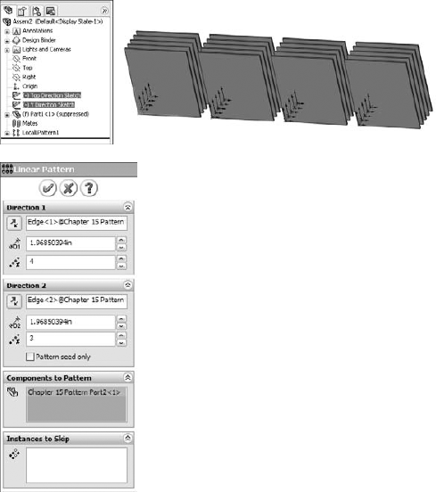
Notice where the pattern is placed in the FeatureManager. You can reorder the pattern feature in the design tree, but you cannot move it above the mates. Interestingly, you can move the sketches after the pattern, even though the pattern is dependent on one of the sketches. Obviously, SolidWorks is working with the order behind the scenes in such a way that the user cannot make mistakes.
All of the aspects of the interface should be familiar, such as the direction, instances, and spacing. The Pattern Seed Only option is also used in feature patterns.
Patterning the seed only is designed to allow you to create a single pattern in two directions that are separated by 180 degrees, where the internal instances do not overlap one another. For example, if you take a basic two-directional pattern and change the angle between the directions so that they are anti-parallel (parallel but going in opposite directions), then all of the component instances that were between the two legs of the L created by the two directions will come to overlap one another when they are laid out in a straight line.
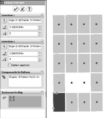
Figure 15.2 shows how a 5-by-4 pattern with 20 instances becomes a 1-by-8 (the seed is not counted twice) pattern. When this happens, the other 12 instances are overlapping the remaining ones. When you use the Pattern Seed Only option, you are only patterning the two legs of the L, and not the instances in between. This can cause problems with BOMs and mass properties.

The Instances to Skip option for component patterns, shown in Figure 15.3, works just like the equivalent option for features. Click the dots in the graphics window to toggle each instance of the pattern.
Derived component patterns have two main limitations: they cannot be driven from either curve-driven or fill patterns. The remaining pattern types that work with derived component patterns are linear, circular, sketch driven, and table driven.
By their very nature, derived component patterns break some of the best practice suggestions in this book, because the pattern is driven by part geometry, and the part must first be solved (by solving features internal to the part) and then placed (by solving mates); only then can the derived pattern be solved. Still, I recommend using derived patterns over local patterns when available because of the parametric link.
Note
For the derived component patterns, the location of the initial component is important. You need to match the placement of the initial component with the position of the original feature from which the pattern was created, not one of the patterned instances.
Figure 15.4 shows the PropertyManager interface for a derived component pattern.
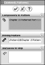
You can nest derived component patterns such that one component pattern is patterned by another component pattern, just like feature patterns. The second pattern can be a local pattern or a derived pattern.
Figure 15.5 shows the RMB menu for a component pattern.
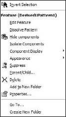
The Dissolve Pattern option removes the component instances from the pattern feature and puts them in the main part of the assembly FeatureManager. The components just become normal components in the assembly without the intelligence of the pattern feature placing them. The components are left in the assembly without any mates, simply floating in position.
You can add patterns to folders. If you have a list of patterns at the end of an assembly, it may make sense to group them into related folders for the purpose of organization. This is the same as using folders for features, mates, or components.
The individual component pattern instances can have their color and other display options changed individually or collectively as a pattern feature. Figure 15.6 shows the display pane where you can control these display options.
Individual instances of the component pattern also enable you to control configurations. After you create the pattern, you can select individual instances and change their configs. This can be extremely useful if you have a mechanism subassembly shown in various positions, for example, patterned around an indexing dial.
To learn how to create component patterns, follow these steps:
Open a new assembly. Create a new sketch on the Top plane, with two lines from the Origin out at odd angles so that they do not pick up horizontal or vertical automatic relations.
Apply dimensions between one of the lines and the Right plane, and set the angle to zero degrees.
Apply a second dimension to the other line from the Front plane, again with an angle of zero degrees.
Open the part from the CD-ROM named Chapter 15 Pattern Part.sldprt. This part already contains several features so that you can practice using derived component patterns.
Insert the part into a new assembly. Locate the part at the assembly Origin such that the part Origin matches the assembly Origin.
Open the part called Chapter 15 Patterned Part.sldprt, and place it in the assembly. Remember that it is important to match the part up with the original patterned feature, and not to just place it on any instance of the feature pattern. The original features are colored red in the part.
Note
Under normal circumstances, the patterned instances are the same color as the patterned feature because of the Propagate Visual Properties setting, which is turned on by default in all of the pattern feature types. For this part, I turned this setting off for each pattern feature so that the original feature could be a different color than the rest of the pattern.
One notable exception to this is the Table Driven Pattern, which appears to have a bug: if you turn off the Propagate Visual Properties setting and exit the feature, it just turns it back on. In this case, the hole colors were changed by changing face colors rather than feature colors.
Place the part on one of the original features. Remember that Alt-dragging the circular edge on the flat side of the part allows you to SmartMate the part to the round holes. It cannot help you with the rectangular or hex holes. For these, it may be best to show the sketch for the holes and place the part with respect to the sketch entities.
Create feature driven patterns (Insert

Once you have created a few feature-driven patterns and have a better understanding of how it is done, you can create a local pattern (Insert
Select the sketch line that was drawn in the Z direction as the direction.
RMB click the top level of the assembly FeatureManager and select Collapse Items. Highlight the Components to Pattern selection box. Select the first part in the FeatureManager and then Shift-select the last pattern feature. This patterns everything in the assembly.
Make the spacing four inches with three instances.
Create a second direction using another of the sketch lines with six-inch spacing and four instances.
Notice how the preview shows 12 instances of the patterned assembly. Click the option for Pattern Seed Only and see how the preview changes to seven instances. Click OK to accept the feature.
Change the zero-degree angle in the sketch created in steps 1 through 3, to 30 degrees. You may have to press Ctrl+Q to get the assembly to update properly.
Performance and best practice are both issues that require compromise. Patterns can cause a performance reduction because of the nature of the references. However, they can also improve performance because the need for extra mates is reduced and it is easier to simplify the assembly by suppressing the pattern feature.
Derived patterns are driven by feature patterns, and transgress more best practice suggestions, but they also add a parametric link, which updates the component pattern automatically.