
IN THIS CHAPTER
Display States
Assembly configurations
Exploded views
Tutorial: Working with assembly configurations
Assembly configurations enable you to control many things, including part configurations, suppression, visibility, color, and assembly feature sizes. They also allow you to control assembly layout sketch dimensions, mate values, suppression states, and several other items. What you will learn in this chapter about assembly configurations builds on the information in Chapter 10, which discussed part configurations. In this chapter, design tables will also be expanded upon to show how they are used in conjunction with SolidWorks assemblies.
The Display States function was new in SolidWorks 2006. Display States are a better performance alternative to using configurations to control visibility of parts in assemblies. Display State options are discussed at length in this chapter.
If you are using an older version of SolidWorks, then you may not have access to Display States, which were not introduced until SolidWorks 2006. They are a very useful addition to the software as they allow you to visualize the assembly in various ways. One of the best things about Display States is their ability to show parts in different display modes (Shaded, Wireframe, HLR, Shaded with Edges) simultaneously.
Users have always been able to show parts transparent and shaded at the same time, and a common workaround for combining Shaded and Wireframe modes was to display the parts as Shaded with Edges, but to make some parts completely transparent. This would give the effect of some parts being shown in Wireframe mode. Because of Display States, this workaround is no longer necessary.
You can copy Display States between configs. To control the display, you can use the Display pane that flies out from the FeatureManager when you click the double-arrow icon in the upper-right corner of the FeatureManager. This is shown in Figure 2.1 in Chapter 2. Figure 14.1 shows the Display pane in action, along with an assembly showing parts in different Display States.

The column symbols for the Display pane are as follows:
Note
The difference between a component and a part in SolidWorks assemblies is that a component is a generic way of identifying any top-level item in an assembly, and may be a single part or a subassembly. It always refers to a specific instance of the part within the assembly. In the case shown in Figure 14.1, the gripper jaw part is used twice, and so there are two instances of the gripper jaw. One instance has its component color set to yellow, and the other instance uses the part color. (The component color is also referred to as an override of the part color). The part color is what you see when you open the part in its own window. The component color is only set in the assembly, and you can only see it in that particular assembly; it never affects how the part displays in any other assembly that the part is shown in.
When there is a difference between the part and component properties (when an override exists), the component property appears as the upper-left triangle, in the color column of the Display Pane and the part property appears as the lower-right triangle. You can only see these triangles in the Color and Texture columns.
Color hierarchy is discussed in Chapter 3, but I will briefly summarize it here, showing the lowest priority at the top:
Part
Body
Feature
Face
Component
If you override a color, display mode, or texture for a component in a subassembly, and the upper-left triangle appears in the Display pane, then you can remove the override through either the Left Mouse Button (LMB) or Right Mouse Button (RMB) menu. Figure 14.2 shows the LMB menu from a component of a subassembly with overrides.

When you select Clear Override, SolidWorks clears any overrides for the currently selected subassembly component. Clear All Top Level Overrides clears all overrides in all subassemblies in the entire top-level assembly. There is no intermediate option to clear all top-level overrides for a particular subassembly; if you want to distinguish between overrides at that level, then you need to clear several individual overrides. The options to remove overrides do not affect top-level components.
The active Display State appears in angle brackets after the configuration name and the filename at the top of the FeatureManager, as shown in the image to the left in Figure 14.3. Display States are created and managed in the ConfigurationManager, in folders under the configuration name, as shown in the image to the right in Figure 14.3. To create a new Display State, simply right-click the Display State folder under the active configuration and choose Add Display State. You can manage Display States in a way similar to the way in which Exploded Views are managed.

New configurations are always created with a default Display State named Display State-1, just as parts always have a default configuration named Default. To copy the New Display State shown in Figure 14.3 from the Default configuration to Configuration 2, you can Ctrl-drag it from one Display State folder to the other configuration's folder.
Note
Display States offer a huge performance gain over configurations when used to control display of parts. The reason for this is that SolidWorks saves some model information for each configuration. In the past, configurations were sometimes created only for display purposes, and changing configurations required reading the model geometry again. When a configuration is created only for the purpose of hiding or coloring a part, this takes up a lot of additional file space and CPU time. Display States change much faster than configurations, almost instantaneously, and they add very little file size to use.
Display States can be shown on drawings if you have set the view to a Shaded Display mode. If you set the view to a Wireframe mode, then SolidWorks ignores the Display State, and all of the parts in the view display in that mode. Drawing views are discussed in depth in Chapter 21.
Assembly configurations are used for many different purposes, including assembly performance, simplified assemblies, variations of assemblies, assemblies in different positions or states, and many others. Like part configurations, assembly configs also have a few best practice type suggestions. Configuration settings for assemblies control how the assembly appears in a Bill of Materials (BOM), what happens to parts, features, or mates that are added to other configurations, and so on. All of these are discussed in this section.
One of the best tools to make large assemblies easier to work with is assembly configurations. You can use several techniques to improve the speed of working with assemblies. Although this information is presented in a list of techniques, it is important to select a method that fits the situation.
The most obvious use of configurations for improving assembly speed is to have a configuration or several configurations with suppressed components. One thing to watch out for when doing this is that configurations are not used in the place of subassemblies. If subassemblies are appropriate for the task, then you should use subassemblies. If not, then you should group and suppress parts using configurations.
Tip
Remember that you can use a folder for parts and suppress the folder.
Schemes that you may want to use for suppressing parts are to have configurations that isolate functional areas of an assembly, configs that remove the fasteners or purchased components, configs that remove complex parts, configs that only leave the parts used in in-context relations, configs that suppress patterns and assembly features, assembly configs that use simplified part configs, configs that show the assembly in different positions, or variations of the assembly using different part configurations. So many possible schemes for creating assembly configurations exist that it is pointless to try to list them all. Use your imagination, make sure that it makes sense, and give it a try.
Tip
Avoid using fasteners to locate parts. The relationship should go the other way (fasteners should be located by the holes in parts). You should already have in place any parts that the fastener stack will touch before the fasteners are added. If parts added after the fasteners are either mated to the fasteners or the holes are created from the fasteners using in-context techniques, then suppressing the fasteners also suppresses the mates that locate those parts, and will cause problems with any in-context features.
If you suppress the "ground" part or any part that connects groups of parts, keep in mind that this can cause other parts to float in space, unattached to anything. Obviously this is not a good situation, and you should avoid it if possible. One way to avoid it is to use an assembly layout sketch and mate the parts to the sketch instead of to the ground part.
Aside from components, other items can also be suppressed to improve performance, such as assembly features and component patterns. Do you really need to see all of those parts patterned around the assembly to work on it in a simplified representation? You may be able to suppress the parts. If you feel that you cannot suppress parts, then consider at least using Display States to hide parts that are needed to complete the parametrics but do not need to display.
Note
The biggest killer of assembly speed is the dreaded circular reference. You can make circular references in a couple of different ways, but they are usually the result of mixing history-based functions (mates, in-context sketch relations, feature references) with non-history-based functions (parts shown in the Assembly FeatureManager). This allows you to create partial or complete loops of references, where A references B which references A. These are a particular problem with in-context references, which are discussed in more depth in Chapter 16.
I have discussed simplified part configurations in Chapter 10, and they can consist of configs with cosmetic features such as small fillets and extruded text, or other cosmetic details that are suppressed. Assembly configurations can use different part configurations, which, for example, would enable you to make an assembly config called "Simplified," and in it reference all of the Simplified part configurations.
Tip
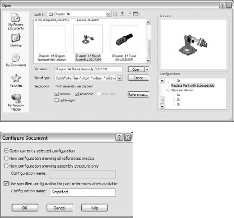
When opening an assembly through the Open dialog box, the Advanced option enables you to open the assembly and create a new assembly configuration that uses part configurations of a given name, if available. The default part configuration name entered in the text box is, I think, suggestive of how SolidWorks intended for this function to be used. As shown in Figure 14.4, it is "Simplified."
Other special operations for assembly configurations in the Open dialog box include creating a new configuration that has all of the components suppressed. This allows you to see the structure of the assembly without fully resolving all of the components. Another option is to open the assembly with a new configuration, where all of the components are resolved. Beyond that, the Open dialog box also allows you to select a specific configuration to open to so that you do not have to wait for the last saved config to load and then make the change.
Note
When you use a part that has several configurations in an assembly, you cannot edit the part in the assembly unless the active configuration is the same as the config used in the assembly. This has always been the case. What is new about SolidWorks 2007 is that if you open the part in its own window from the assembly, SolidWorks automatically makes the config that is used in the assembly the active config. As a result, to change the active config and edit the part in the assembly, all you have to do now is to open the part in its own window and then switch back to the assembly (using Ctrl+Tab).
It is curious that this option is not so easily available after the assembly is already open. However, you can use some other techniques to sort through parts. The Advanced Show/Hide Components dialog box is shown in Figure 14.5. You can access this dialog box by right-clicking the configuration name in the ConfigurationManager.

This tool enables you to establish search criteria and show or hide parts, based on the criteria. Multiple criteria can be used, stored, and retrieved. This tool is generally underused, and in my experience, users are always surprised to find it in the software. It has been there since about 1998.
Note
A function called Isolate is new to SolidWorks 2007. This works like the inverse of the Show command. If you select multiple parts and click Isolate from the RMB menu, the selected parts remain shown, and everything else becomes hidden. A little pop-up gives you the option of showing the removed components in a Wireframe or Transparent display mode, or of saving the current display as a new Display State. This is a very useful function, as shown in Figure 14.6.

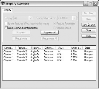
If you have the SolidWorks Office bundle or higher, then you can activate the Utilities add-in. You can do this by selecting Tools, Add-ins, and then turning on Utilities. This displays a Utilities menu with the Simplify option. The Simplify Assembly tool is shown in action in Figure 14.7.
The Simplify Assembly tool can find features in the parts of the assemblies that are under a certain size or that take up less than a certain percentage of the volume of the part. You can then suppress these features in special derived configurations.
Overall, SolidWorks performance is split into two categories: CPU (central processing unit) processing and GPU (graphics processing unit) processing. This is essentially the difference between calculating the parametrics and geometry, as opposed to the graphics and display. Which of these functions your computer performs better can vary widely, depending on your hardware, drivers, and system maintenance, among other factors.
When trying to speed up the performance of an assembly, the biggest impact is obviously made if you can reduce the load on both the CPU and the GPU. You can do this by suppressing a part. When a part is suppressed, it is neither calculated nor displayed, and so the load on each processor for that part is zero.
When you hide a part, its parametric features are still calculated by the CPU; however, because the part is hidden, it creates no load on the GPU. If you have a good main processor and a questionable video card, then you will achieve a greater benefit from removing graphics load from your display.
On the other hand, if you want to still show a part but not calculate any of its parametric relations, then you should use Lightweight parts. You can find Lightweight default settings in Tools
To summarize this section, there is a four-way relationship between the Resolved, Lightweight, Hidden, and Suppressed states, as shown in Figure 14.8.

The terminology becomes a little convoluted here because of the relationship between the four different states. In parts, the feature states are easy to remember because features can be either suppressed or unsuppressed. However, in assemblies, there are four states instead of two, and so unsuppressed could mean anything that is not suppressed, which still leaves three states. For this reason, resolved is used instead of unsuppressed when dealing with components in an assembly.
When you use configurations to display an assembly in various positions, you can do this in a couple of ways: by changing mates or by changing a layout sketch. Mates are configurable in two ways: mates can be suppressed and unsuppressed, and angle and distance mate values are configurable in the same way that sketch dimensions are configurable. Although creating a mate scheme that enables you to reposition the assembly using mate suppression states and values is essential to this method, it may not be the best approach.
Using a skeleton or layout sketch to mate parts to may be a better approach, although this also has its drawbacks. If you mate to a layout sketch, you cannot make use of Dynamic Assembly Motion. If you use the mate scheme discussed above, this generally means having a fully defined assembly, and this also does not allow for Dynamic Assembly Motion.
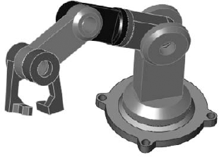
As a compromise, a good way to handle this is by using one configuration for Dynamic Assembly Motion, with one or more open degrees of freedom. You can use other configurations to fully define the mechanism and show it in particular positions using either method. Probably the best way to demonstrate this is with an example using the robot arm assembly.
First, let's take a look at positioning with mates. On an assembly such as this one, the goal is to position the grippers. You can do this in a couple of ways, both directly and indirectly. In the assembly used for this chapter, the grippers have been rebuilt as a subassembly, which allows different types of control. Notice that the subassembly has a configuration for the closed position and one that allows Dynamic Assembly Motion. Also, the subassembly is being solved as Flexible. Figure 14.9 shows the assembly and the FeatureManager.
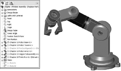
A sketch point has been added to the subassembly to precisely identify the point on the gripper that is to be positioned. Sketch points have also been added to the main assembly to represent parts that need to be picked up by the robotic arm.
Note
For a better range of motion, this arm should probably have an additional pivot that enables motion out of the plane of the Tower part.
Check the derived configurations under the default config. Notice that when you switch between certain configurations, the parts seem to separate. Moving one of the links causes the parts to snap back together again. This is probably because there are so many options when moving between configurations that the software has difficulty choosing a final position. This is definitely one of the potential problems when using configured mates to show an assembly in various positions.
Notice also that although the grippers are positioned correctly, the arm is still allowed to swivel around the intended target point. You can correct this by defining an orientation for the grippers for each location. If the additional pivot were added to the assembly, then fully defining the parts would become more difficult. The arm would not be able to reach any additional points, but it would not be so limited in orienting the grippers at each point.
You can also use mates to drive configured positions of the assembly using a series of angle mates. This makes it more difficult because to get to a particular location, you have to do some calculations, but the angle mates appear to be more stable than simply relying on moving the parts to unconstrained positions.
If you cycle through the derived configurations under the Indirect top-level configuration, notice that mates are not suppressed and unsuppressed, rather the values are changed. This makes it somewhat more difficult to precisely position the grippers, but because it is specific about the positions of the individual parts, there is no ambiguity.
Although this technique is still using mates to position the parts, to change the position, you change sketch dimensions rather than mate values. Sketches used to drive parts from an assembly are sometimes called layout sketches or skeletons. These are also discussed in Chapter 16 for in-context or top-down assembly techniques and Chapter 11 as a way of controlling parent/child relationships. Figure 14.10 shows the same assembly that is used for the rest of this chapter.
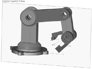
This particular assembly is driven by two sketches on different planes to govern the position of the parts. Keep in mind that this assembly has been used for all of the other techniques as well, and so all of these techniques can exist together simultaneously, being controlled by configurations.
Examine the assembly to see how the parts are mated to the sketches. This is important. The first time you create a part such as this, you may be tempted to mate part planes to the sketch lines.
Warning
Mating planes to sketch lines has a very serious drawback that you must be aware of. Unlike other types of mates, which have an alignment that you can control, plane-to-sketch line mates cannot be aligned. This means that the software is as likely to align elements correctly as incorrectly on any plane-to-line mate.
Note
A better way to mate part planes to sketch lines is to mate the Temporary Axes through the joints with the sketch endpoints. This solves the alignment problem.
In this case, product variations means variations in size or part replacement. Some examples are a 4-foot cabinet and an 8-foot cabinet, or a two-button mouse and a three-button mouse.
As a simple example, Figure 14.11 shows the familiar robotic arm assembly, but with a variation: one of the arms has been replaced with a subassembly. The subassembly is made of the original replaced part using configurations, and there are configurations of the subassembly, which is again being used as a flexible subassembly.
Through the course of this chapter, the robot arm assembly has greatly increased in complexity, but it has retained the original information that was in the first version. Maintaining valid assembly data through manually managed configurations is difficult, and all it takes is a simple mistake to wipe out a lot of assembly configuration data. Appropriately, the next section discusses assembly design tables.
Chapter 10 dealt with part configurations and created a good framework for design tables in general. This chapter augments that information with what you need to know to use design tables effectively in assemblies.
Assembly design tables can do everything that part design tables can do, except for selecting configurations of base parts and split parts, which are not valid assembly functions. Assembly design tables can also do some things that a part design table cannot. These include:
Assigning the Display State for a configuration
Suppressing the state of a part (R for Resolved or S for Suppressed)
Assigning the component configuration for the assembly config
Allowing you to activate the Never Expand in BOM option
If you have been using design tables for a while and are familiar with older versions, then you may have noticed that the $show parameter, which specified whether the part was shown or hidden, has become obsolete due to the new functions of Display States.
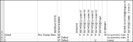
Figure 14.12 shows the design table that results from auto-creation using the robot arm assembly. Some of the columns have been hidden to make it small enough to fit on the page. If you want to see the entire table, you need to open the assembly. If you edit the design table, then you will probably want to use the Open in Separate Window option, which is easier to navigate and control.
Avoid using Delete as an editing option when working with configurations. Delete is forever and for all configs.
Avoid the use of in-context relations to size parts when you are also using configurations to size parts. A non-configured part driven by a configured part only causes confusion.
Avoid using configurations to represent document control type revisions. I have seen people attempt to do this, but in the end, it limits the kinds of edits you can make to your parts and assemblies, and it is far too easy to make a mistake that wipes out all of your diligence. In the end, this is not a viable technique.
If you are working with manually created configs, then you should create a new configuration and activate it before making the changes. Otherwise, you will end up trying to set the original config back to the way it was.
Remember to select the This Configuration Only option for changed dimensions, instead of leaving it at the default All Configurations setting.
Exploded views enable you to display an assembly taken apart so that you can see all of the parts. They are great for assembly documentation, assembly instructions, and for visualizing assemblies with concealed internal parts.
I have included exploded views in the assembly configurations chapter because, like Display States, exploded views are found in the ConfigurationManager under the configuration. Each config can have multiple exploded views, and you can copy exploded views between configurations.
When you are creating the exploded view of the top-level assembly, and a subassembly already has one, you can include the subassembly's exploded view in the top-level exploded view. While you are creating exploded views, mates are temporarily suspended.
To initiate a new exploded view, switch to the ConfigurationManager, RMB click a configuration name, and select New Exploded View, as shown in Figure 14.13.
Figure 14.13 also shows the Explode PropertyManager interface. This interface includes a helpful How-To section at the top to give you a hint of where to start.
If you are creating assembly instructions or an animation from the exploded view (using Animator or the RMB options, Animate Explode, or Animate Collapse), then you may need to be more careful about how the parts are exploded. You can create explode lines that show how the parts go back together.

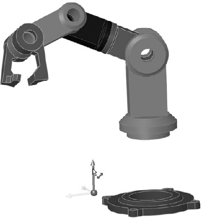
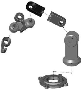
To begin, you can explode the Base and the Tower down and back, respectively. A single part can explode in multiple directions, or multiple parts can explode in a single direction. These two parts are shown exploded in Figure 14.14. Select the base, and then drag the arrow of the Triad that moves in the direction that you want the part to move.
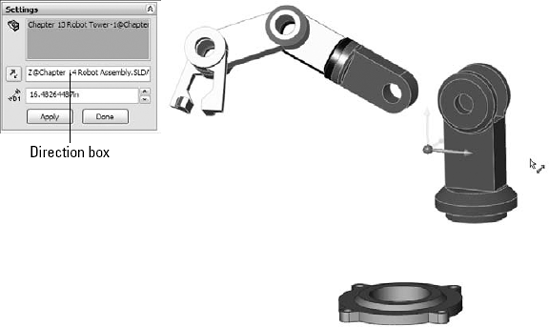
The Tower part is a little more difficult because it is not lined up with the direction in which it needs to be exploded. To remedy this, highlight the Direction box in the PropertyManager and select a face that is normal to the direction that you want to drag, or an edge that is in this direction. Then drag the appropriate arrow on the triad again, as shown in Figure 14.15.
Tip
SolidWorks Help says that you can drag the sphere of the triad onto a face to change the direction, rather than selecting a face in the Direction box. However, it fails to mention that you have to hold down the Alt key while dragging it, in order for it to stick to an entity.
Exploding the Twist Arm subassembly provides the opportunity to show a couple of useful subassembly functions. You can explode the parts of a subassembly either together as a unit or individually. You can even reuse explode steps from the subassembly, which is what you will do here.
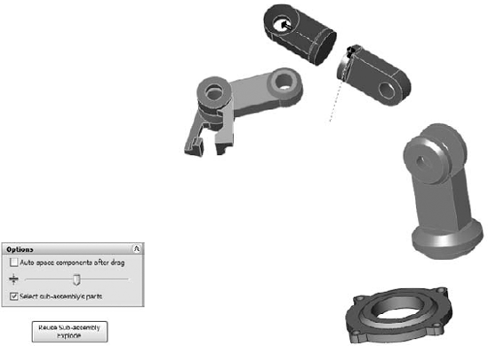
To explode the subassembly as a single part and then reuse its explode steps from the subassembly file, ensure that the Select Sub-Assembly's Parts option is off, as shown in Figure 14.16.
Warning
You cannot reuse a subassembly's explode steps if the subassembly is set to Flexible. SolidWorks will tell you that there are no explode steps to reuse if you try to reuse the explode steps of a flexible subassembly. In order to work around this, you can set the subassembly to solve as Rigid, reuse the explode steps, and then set the subassembly back to Flexible. Although awkward, this is an effective workaround to this problem.
Tip
While exploding the parts, you should rotate the view from time to time. Unless you are creating the explode for a particular point of view, the explode may look very different if you rotate it a little.
For the final explode step, the grippers will explode individually in opposite directions. Remember that these parts belong to another subassembly. If you create an explode step with the Select Sub-Assembly's Parts option turned off or on, you will not be able to change it later, and so you need to pay careful attention to what you are doing.
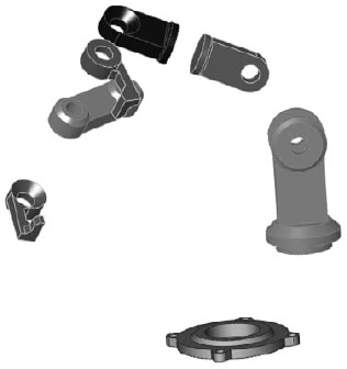
Turn on the Select Sub-Assembly's Parts option, select one gripper, Alt-drag the triad to set the direction, and then drag the distance of the explode. If you are in the mood to submit an enhancement request to SolidWorks, then you may want to request a Symmetrical Explode function for situations such as this. Figure 14.17 shows the finished result of the explode.
You may have noticed that each explode step creates a dashed line to show where the explode came from. Unfortunately, these dashed lines cannot be turned into usable explode lines on documentation. You must create explode lines manually, using 3D sketches. Although 3D sketches can be very tricky to use, for this purpose, you can limit their function to simple straight lines. As long as you try for simple results, the Explode Lines feature should work well.
Before I begin to discuss the Explode Lines feature, we should take a minute to look at the terminology, which can be confusing. For example, the opposite of explode is collapse. Unfortunately, the opposite of expand is also collapse, and so when the assembly is exploded and you want to collapse it, the RMB menu on the Exploded View displays one entry called Collapse and another called Collapse Items. You must remember that Collapse Items refers to expanded ConfigurationManager lists, while Collapse refers to un-exploding the Exploded View.
Another example is that the PropertyManager and Tooltips call the function Route Line (which can be easily confused with a function of the SolidWorks Routing software), but on the toolbar and menu, it is referred to as Explode Sketch. Further, the tool that you use to start the Explode Sketch function is on the Explode Sketch toolbar itself, and does not seem to exist on any other toolbar. You must access it from the Insert menu, by selecting the command called Explode Line Sketch. Figure 14.18 shows some examples of the above-mentioned terminology.
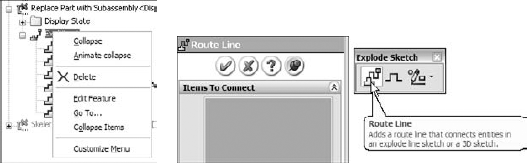
Figure 14.18. Interface and terminology inconsistencies in the exploded view and Explode Line functions
To initiate the Explode Line Sketch function, you can select Insert
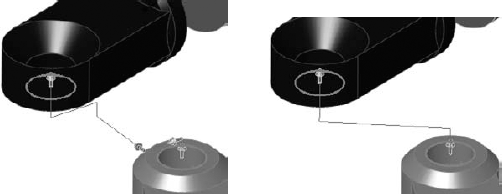
If after you have selected two circular edges, the explode line goes the wrong way, you can click the arrow at the start of the line. Notice in Figure 14.19 that the line seems to take an unnecessarily circuitous route. This is because the explode directions were not square to the assembly Origin. To work around this problem to some extent, you can deselect the Along XYZ option in the Route Line PropertyManager. You can move the jogs by bringing the cursor close to the line, and selecting the arrows that pop up.
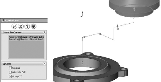
Figure 14.20 shows the difference between using the Along XYZ option (image to the left) and turning it off when the explode was not square to the assembly Origin (image to the right).
The completed explode lines are shown in Figure 14.21.
You can animate the explode or collapse from the RMB menu. To do this, right-click the exploded view, and select Animate Explode or Animate Collapse. This method does not offer recording or Photoworks rendering like Animator software, but it is fast and easy.
To begin this tutorial, open the assembly named Chapter 14 Bike.sldasm. This assembly is made from the same parts as the assembly that was used in Chapter 12, but it will be used differently here. This file contains all of the aspects that we need to work with in this chapter, including subassemblies, motion, and part configurations.
Note
You can ignore the warning symbols in the BibleBikeFrame part file. These are caused by the Fill feature that is discussed in Chapter 27.
To learn how to work with assembly configurations, follow these steps:
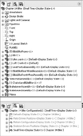
Prepare to use configurations by splitting the FeatureManager window into an upper and lower pane. Place the FeatureManager on the top and the ConfigurationManager on the bottom.
Before starting to make changes to this assembly, add the top-level configurations that you will need, as follows:
Small Tires
Motion Configuration
Skeleton Driven Positions
Mate Driven Positions
The configurations will list alphabetically.
Make sure that the Advanced Options of each configuration are set to Suppress New Features And Mates and also Suppress New Components.
Activate the Small Tires configuration. Figure 14.22 shows the FeatureManager up to this point.
Open the Front Wheel Assembly in its own window and switch to the ConfigurationManager. Add a configuration called Small Tires, and change the tire to the configuration called Small Tire, which has already been created.
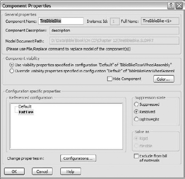
Switch back to the main assembly window (using Ctrl+Tab), RMB click the Front Wheel Assembly in the FeatureManager, and select Component Properties. Select the Default configuration for the Front Wheel assembly, as shown in Figure 14.23.
Repeat steps 4 to 6 for the Rear Wheel assembly.
Double-click another configuration from the list and watch the assembly change from small to fat tires.
Change to the Motion configuration. RMB click the Stem-Fork assembly, select Component Properties, and set the assembly to be solved as Flexible.
Exit the dialog box and check to see that the fork linkage mechanism moves by dragging the fork. Notice that the fork works but that the front wheel does not move with it. The bike design is not yet complete, and so you do not need to worry about that at this point.
Switch to the Skeleton Driven Positions configuration.
Display the assembly Layout Sketch at the top of the FeatureManager.
Create two new derived configurations under the Skeleton Driven Positions configuration, one called Default Position and the other called Compressed Position.
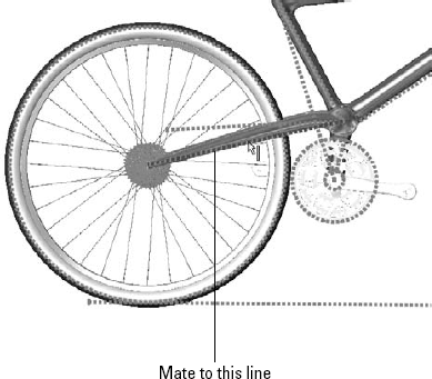
Activate the Default Position configuration, and make a coincident mate between the Top plane of the Chainstay part and the sketch line indicated in Figure 14.24.
Activate the Compressed Position configuration and make a coincident mate between the same plane and the line that is angled up at 10 degrees.
Note
For these configs you also need to set the Advanced options just as you set the top-level configs in step 3. If you do not do this, then you may need to manually suppress the unwanted mates in the appropriate configurations.
Switch to the Mate Driven Position configuration.
Add new derived configurations called 1, 2, and 3. While creating the new configs, ensure that the Suppress New Features and Mates and Suppress New Components options are selected.
Make an angle mate between the Bike assembly Top plane and the face of the link, as shown in Figure 14.25.
Once the mate is complete, double-click the angle dimension (you may have to double-click the angle mate to get it to display and then zoom out to see it), and change the value to 18 degrees.

Note
You need to set the Fork assembly to solve as Flexible for each configuration. You may also need to control the alignment for the angle mate manually for each configuration.
Display States in the assembly can save a lot of time because they change faster than configurations and offer more options for visualization, including mixed display modes. You can save and copy multiple Display States between configurations. Assembly design tables can select Display States and drive many other parameters in assemblies.
The Exploded View functionality in SolidWorks has some unusual aspects that you need to work around; however, it is a valuable and useful function, and is worth the extra steps.