
Chapter 18. Advanced Buffers
WHAT YOU’LL LEARN IN THIS CHAPTER:
• How to improve performance with pixel buffer objects (PBOs)
• How to perform offscreen rendering with framebuffer objects (FBOs)
• How to use floating-point textures and color buffers
• How to put it all together and render with high dynamic range
Shaders by now are old hat. Been there, done that. Yawn. The most exciting new advances in OpenGL over the past several years involve buffers. In particular, the flexibility with which you can designate blocks of GPU memory for a variety of purposes enables rendering techniques which were before impossible or too slow to consider using. No longer are vertex arrays, textures, and framebuffers individual and segregated entities. Today you can mix-and-match this data—read it, write it, and render with it from different stages of the OpenGL pipeline. And with new single-precision floating-point data formats, the sky is the limit. Or in deference to IEEE 754, 3.4×1038 is the limit.
This chapter covers the OpenGL APIs making this new-found flexibility possible: pixel buffer objects, framebuffer objects, and floating-point internal formats for textures and renderbuffers. Each feature will be explored in isolation with one or two samples. Then they will all join hands on stage for a final curtain call where they team up to provide high dynamic range bloom and afterglow effects.
Pixel Buffer Objects
Pixel buffer objects, commonly referred to as PBOs, are a new class of buffer objects available in OpenGL 2.1. You may remember the original class of buffer objects, vertex buffer objects (VBOs), described in Chapter 11, “It’s All About the Pipeline: Faster Geometry Throughput.” Although the mechanics are the same, their intended usage is different.
Hint: PBOs are intended to contain pixels instead of vertices.
Like VBOs, PBOs are considered server-side objects. This allows the OpenGL driver to place them in video memory next to the GPU, or wherever else it thinks performance will be optimal. And like VBOs, the same usage hints (what the app plans to do with the data, and how frequently) can influence the decision as to where to place the PBO in memory. If the data will be written once and then used for rendering repeatedly, local video memory may be fastest, whereas if the data is constantly being read back or replaced by the CPU, the PBO may be better situated in host-readable system memory.
By binding a PBO to one of two new buffer object targets, described next, any OpenGL command that traditionally expects a pointer to client memory (that is, memory allocated by your application) to send in or read back blocks of pixel data will now use the PBO as the source or destination for that pixel data. Fear not: When we say pixels, we mean texels too!
How to Use PBOs
The commands are identical to those used for VBOs. In fact, the GL_ARB_pixel_buffer_object extension from which this feature originated introduced no new entrypoints. All it brought to the table were two new tokens for buffer object binding targets, and two new tokens to query back the current bindings. GL_PIXEL_PACK_BUFFER and GL_PIXEL_UNPACK_BUFFER are the new targets. GL_PIXEL_PACK_BUFFER_BINDING and GL_PIXEL_UNPACK_BUFFER_BINDING are used with glGet* to query the current bindings. If no PBO is bound, these return 0.
Here’s a refresher on buffer object commands. We generate a name, bind it to create the PBO, initialize its data store, map it to allow direct CPU access and then unmap it, modify a subset of the data store, draw from it, and then delete it:
glGenBuffers(1, &pboName);
glBindBuffer(GL_PIXEL_UNPACK_BUFFER, pboName);
glBufferData(GL_PIXEL_UNPACK_BUFFER, width * height,
myPixelPtr, GL_STATIC_DRAW);
glMapBuffer(GL_PIXEL_UNPACK_BUFFER, GL_WRITE_ONLY);
glUnmapBuffer(GL_PIXEL_UNPACK_BUFFER);
glBufferSubData(GL_PIXEL_UNPACK_BUFFER, width * 5, width, ptrToNewRow5Data);
glDrawPixels(width, height, GL_LUMINANCE, GL_UNSIGNED_BYTE, (GLvoid*)0);
glDeleteBuffers(1, &pboName);
Unpacking refers to taking data from the app and unpacking it for use by the OpenGL driver, as in glDrawPixels or glTexImage2D. Packing, on the other hand, is when pixel data is packaged up and returned to the application, such as via glReadPixels or glGetTexImage.
Notice that the call to glDrawPixels in the preceding code snippet is passed a pointer value of 0. Just as for vertex array pointers when a VBO is bound, the pointer is treated as an offset into the currently bound buffer object. The 0 means the driver should start unpacking at the very beginning of the buffer object’s data store. A nonzero value would indicate that the unpacking should start some number of bytes past the beginning.
You can use glBindBuffer to switch between different PBOs. Binding buffer name 0 to a target will effectively unbind the currently bound PBO, if any, returning to traditional usage of client memory for the associated binding point. Another interesting thing to note is that a buffer object can be simultaneously bound to multiple targets, those for both PBOs and VBOs!
The Benefits of PBOs
There are several specific benefits that summoned PBOs into existence. All of them are performance-related. An application has always been able to send pixels and texels from client memory into the driver, and read them back into client memory, copy them around, and use the data for different purposes. PBOs simply allow the driver to take some shortcuts that can improve performance. These are the specific performance benefits:
• Caching frequently used data close to the GPU
• Avoiding an extra copy from client memory to the driver
• Allowing reads from the framebuffer to be pipelined
• Data repurposing without explicit copies to and from client memory
The first benefit is identical to that achieved with VBOs. Just as frequently used geometry data can be placed into a VBO that the driver might decide to cache in video memory for fast access during rendering, the same can be done for frequently used pixel data. For example, if you redraw the same GUI components, cursor, or other 2D element over and over again, that pixel data has to be unpacked from client memory and sent to the GPU every time. This is because the driver has no way of knowing if the client data has changed in between calls, so it has to assume that the data is different each time. Putting the data into a PBO, where the application can touch it only by calling OpenGL commands like glBufferData or glMapBuffer, gives the driver an assurance that it can safely relocate your data and reuse it with lower per-draw costs.
The second benefit stems from the typical usage pattern for applications loading textures from disk. Consider your favorite OpenGL game. As you complete one level and move on to the next, don’t you hate waiting for that progress bar to advance from one side of the screen to the next? Much of this time is spent loading textures from disk and sending them into the driver. Traditionally, the application allocates client memory, loads the texture data from disk into the client memory, and hands the pointer to the driver with a call like glTexImage2D. The driver then needs to copy that data from the client memory into its own memory before returning from the call. Remember, as soon as glTexImage2D is complete, the application is allowed to modify that memory and use it again for its next texture if it so chooses! If, instead of allocating its own client memory for the texture, the application calls glMapBuffer on a buffer object, the application could load the texture straight from disk into the driver, avoiding an extra explicit copy into client memory along the way. Considering the gigabytes of texture data used by games these days, copying more often than you need to is just a waste!
The third benefit shifts attention away from sending data into the driver, and instead focuses on reading data back out of the driver. In particular, calling glReadPixels traditionally reads pixels from the framebuffer and packs them into client memory. Upon return from glReadPixels, the data must be ready because the application might start using it immediately. And for that data to be ready, the contents of the framebuffer would first have to be finalized. This means all rendering in the pipeline has to drain out and have its impact on the framebuffer before the pixels can be safely read back. This is why your mother warned you against hanging out with glReadPixels. Now you can tell your mother about PBOs. An application can bind a PBO to the GL_PIXEL_PACK_BUFFER target before making the call. Because the application has to then use an explicit command, either glGetBufferSubData or glMapBuffer, to access the results, the driver no longer has to drain the pipeline to ensure that the results are immediately available. If the application can issue the glReadPixels, go off and do some other useful work, and then come back later to get the result when it is available, no pipeline stalls are needed!
Finally, we can benefit performance-wise by the flexibility of buffer objects. Looking just at PBOs, we can bind the same buffer object to both the GL_PIXEL_PACK_BUFFER and GL_PIXEL_UNPACK_BUFFER targets and effectively grab texel data from one place and send it back in as pixel data, or vice versa. (Note that glCopyTexImage* already exists to optimize the latter case.) The more interesting combination may be the capability to bind a PBO as a VBO, also known as render to vertex array. Using floating-point formats, you can use the GPU’s shader hardware to generate vertex data that can be read back to a PBO, bound as a VBO, and used for subsequent rendering. Though different OpenGL implementations will have different internal gymnastics they need to perform to make this work, from the application’s perspective, it can do all this without ever copying data into or out of a client memory buffer.
PBOs in Action
The first sample of the chapter is one that is contrived to demonstrate a couple of the more tricky performance benefits of PBOs, the second and third in the earlier list. For every frame that is drawn, we’re going to blend together three textures: (1) an album cover at 50%, incrementally rotated in each new frame, (2) a snapshot of the frame we rendered two frames ago at 25%, and (3) a snapshot of the frame we rendered three frames ago at 25%. The end result is a motion-blurred spinning album cover.
We’re going to read back old frames via glReadPixels and send them back in as textures via glTexImage2D for use as the ghost images for motion blur. To improve performance, we’ll bind PBOs so that our reads from the framebuffer are pipelined. Also, we’ll map the PBO in order to perform the CPU scaling down to 25% without having to introduce a client memory copy. Clearly there are more optimal ways to achieve this effect, such as using fragment shaders to blend the ghost images at the desired ratios. We’re going retro in a number of ways in order to focus on the PBO lessons.
Figure 18.1 shows how three textures are added together per frame to obtain the motion-blurred result. The original album cover at 50% is always contributing, rotated a bit each time. The previous frame does not contribute, because we want to give the glReadPixels a chance to finish without draining the pipeline. The frame before that, which has finished being read back, is mapped so that the CPU can scale its values by 25%. And finally, the frame before that, already scaled by 25%, makes its final appearance as a ghost image before being recycled as the recipient for the next glReadPixels.
Figure 18.1. Three textures contributing to each final frame.

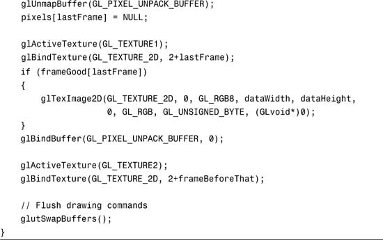
Figure 18.2 shows the results of the main rendering loop in Listing 18.1. The main rendering loop draws the current frame, starts to read back from it, maps the previous frame for dimming, and sends it back in as a texture.
Figure 18.2. PBOs improve the performance of our motion blur sample. (This figure also appears in the Color insert.)
Listing 18.1. The Main Rendering Loop of the PBO Motion Blur Sample


Oh, Where Is the Home Where the PBOs Roam?
You have seen PBOs used in conjunction with basic commands like glTexImage2D and glReadPixels. But what is the full list of commands where GL_PIXEL_PACK_BUFFER and GL_PIXEL_UNPACK_BUFFER come into play? I’m glad you asked.
GL_PIXEL_PACK_BUFFER affects glGetCompressedTexImage, glGetConvolutionFilter, glGetHistogram, glGetMinmax, glGetPixelMap, glGetPolygonStipple, glGetSeparableFilter, glGetTexImage, and glReadPixels.
GL_PIXEL_UNPACK_BUFFER affects glBitmap, glColorSubTable, glColorTable, glCompressedTexImage*, glCompressedTexSubImage*, glConvolutionFilter*, glDrawPixels, glPixelMap, glPolygonStipple, glSeparableFilter2D, glTexImage*, and glTexSubImage*.
The OpenGL 2.1 specification requires that any of these commands be usable with PBOs. Many of them are rarely used, so your mileage may vary!
Framebuffer Objects
Framebuffer objects, known as FBOs, allow you to divert your rendering away from your window’s framebuffer to one or more offscreen framebuffers that you create. Offscreen simply means that the content of the framebuffers is not visible until it is first copied back to the original window. This is similar to rendering to your back buffer, which isn’t visible until swapped.
Why would you want to do this, especially if rendering to an FBO doesn’t show up on the screen?! My answer is threefold, with more details following in subsequent sections:
• FBOs aren’t limited to the size of your window.
• Textures can be attached to FBOs, allowing direct rendering to textures without an explicit glCopyTexImage.
• FBOs can contain multiple color buffers, which can be written to simultaneously from a fragment shader.
FBOs are new enough that they are not yet part of the core OpenGL API. You need to check for the GL_EXT_framebuffer_object extension before using them.
How to Use FBOs
The first thing to understand is that an FBO is just a container for images. Consider the traditional framebuffer that comes with your window. It is also a container of images. At minimum you always have a front buffer, which holds the colors you see on the screen. Almost always you have a back buffer, which is the staging area for your in-progress rendering. Often you have a depth buffer, and sometimes a stencil buffer too. These individual 2D surfaces compose the framebuffer.
Creating and Destroying
You create and destroy your FBO container using familiar commands:
glGenFramebuffersEXT(1, &fboName);
glBindFramebufferEXT(GL_FRAMEBUFFER_EXT, fboName);
glDeleteFramebuffersEXT(1, &fboName);
In addition to creating new FBOs, glBindFramebufferEXT is also used for switching between FBOs. Binding to name 0 will effectively unbind the current FBO, if any, and redirect rendering to your window’s framebuffer.
Now, with what shall we fill our initially empty container? There are two types of images that can be attached to the FBO. The first you’re already familiar with: textures. Since this book is nearing its end, I trust that by now you’re an expert at creating textures. The second type of image is called a renderbuffer. Both textures and renderbuffers will serve as the targets for rendering. The main difference is that renderbuffers cannot be used for subsequent texturing. Also, whereas you can create depth textures (see Chapter 14), stencil textures don’t exist. So, if you need a stencil buffer attachment, or if you don’t intend to turn around and use your FBO attachment as a texture, renderbuffers are for you.
Renderbuffers again use a familiar interface:
glGenRenderbuffersEXT(1, &rbName);
glBindRenderbufferEXT(GL_RENDERBUFFER_EXT, rbName);
glRenderbufferStorageEXT(GL_RENDERBUFFER_EXT, GL_RGBA8, width, height);
glDeleteRenderbuffersEXT(1, &rbName);
glRenderbufferStorageEXT establishes the size and internal format of your renderbuffer. Accepted formats are the same as those accepted by glTexImage*, with the addition of GL_STENCIL_INDEX{1|4|8|16}_EXT formats. You can find the maximum dimensions supported by your OpenGL implementation by calling glGetIntegerv with the parameter GL_MAX_RENDERBUFFER_SIZE_EXT.
Attaching Images
Now to attach our images to our FBO. One requirement is that all attached images have to be the same size. This is a very reasonable requirement. Imagine if the color buffers and depth buffer in your traditional framebuffer were different sizes. What would that even mean? It would be chaos! Another requirement is that all attached color buffers must be the same format. This time I could make arguments for wanting to render simultaneously to different color formats, but alas this is a restriction we’re currently stuck with. Here are examples of the four commands for attaching images to our FBO:
glFramebufferTexture1DEXT(GL_FRAMEBUFFER_EXT, GL_COLOR_ATTACHMENT0_EXT,
GL_TEXTURE_1D, my1DTexName, mipLevel);
glFramebufferTexture2DEXT(GL_FRAMEBUFFER_EXT, GL_COLOR_ATTACHMENT0_EXT,
GL_TEXTURE_2D, my2DTexName, mipLevel);
glFramebufferTexture3DEXT(GL_FRAMEBUFFER_EXT, GL_COLOR_ATTACHMENT0_EXT,
GL_TEXTURE_3D, my3DTexName, mipLevel, zOffset);
glFramebufferRenderbufferEXT(GL_FRAMEBUFFER_EXT, GL_COLOR_ATTACHMENT0_EXT,
GL_RENDERBUFFER_EXT, rbName);
The second argument in each command is the name of the attachment point. This can be GL_DEPTH_ATTACHMENT_EXT, GL_STENCIL_ATTACHMENT_EXT, or GL_COLOR_ATTACHMENTn_EXT where n is 0 through 15. However, today’s implementations tend to support fewer than 16 simultaneous color attachments. You can find the limit of an OpenGL implementation by calling glGetIntegerv with parameter GL_MAX_COLOR_ATTACHMENTS_EXT.
When attaching textures, you need to specify which mipmap level you’re targeting. Remember that a texture is actually an array of images representing the mipmap chain. If your texture isn’t mipmapped, or you’ll be using mipmap generation (more on this later), specifying level 0 is appropriate to target the texture’s base level.
All attached images must be 2D. Renderbuffers and 2D textures naturally fall into this category. Any 1D textures are treated as 2D images with height 1. You can attach one or more individual cube map faces by specifying the face as the texture target. When attaching a 3D texture, you need to indicate which layer of the 3D texture is being attached via the zOffset parameter.
You may at this point have already asked yourself, “What happens if I have a texture attached to the current FBO and also bound to a texture unit that’s currently in use? Isn’t there a paradox in which I’m currently rendering from the same surface I’m rendering to?” The answer is, “Yes, there’s a paradox, and you’ll tear apart the very fabric of space and time, causing the universe to cease existence.” Or your rendering will be undefined. Either way, don’t do it, I implore you.
Draw Buffers
There’s been a lot of talk about multiple color attachments, but how do we address them? For starters, let’s look at the output from OpenGL Shading Language (GLSL) fragment shaders. Most often the fragment shader will output a single color to the built-in variable gl_FragColor. However, it may choose instead to output multiple colors to the gl_FragData[n] array. A fragment shader will fail to compile if it tries to do both!
The single or multiple color outputs still need to be mapped to the FBO’s color attachments. The default behavior is for a single color output to be sent down to color attachment 0. However, this can be altered by a call to either glDrawBuffer or glDrawBuffers, the latter new in OpenGL 2.0 to go along with gl_FragData[n].
When no FBO is bound, glDrawBuffer will behave as it always has, meaning that a single color is mapped to one or more color buffers associated with the window, most popularly GL_BACK_LEFT. However, when an FBO is bound, glDrawBuffer no longer accepts the traditional values of front/back/left/right color buffers. Instead it will accept GL_COLOR_ATTACHMENTn_EXT or GL_NONE, causing a single color output to be sent to the designated color attachment of the FBO or nowhere, respectively.
glDrawBuffers handles the mapping of multiple color outputs from the fragment shader to multiple color attachments of the FBO. In the rare case in which no FBO is bound, you can still direct the multiple colors to individual color buffers of the traditional framebuffer. For example, if you have double-buffering and stereo support in your window, you can target each buffer individually:
GLenum bufs[4] = {GL_FRONT_LEFT, GL_FRONT_RIGHT, GL_BACK_LEFT, GL_BACK_RIGHT};
glDrawBuffers(4, bufs);
However, the common case is going to entail using these multiple color outputs while an FBO is bound, as such:
GLenum bufs[4] = {GL_COLOR_ATTACHMENT0_EXT, GL_COLOR_ATTACHMENT1_EXT,
GL_COLOR_ATTACHMENT2_EXT, GL_COLOR_ATTACHMENT3_EXT};
glDrawBuffers(4, bufs);
Of course, there’s no reason you need to map the color outputs from gl_FragData[0] to GL_COLOR_ATTACHMENT0_EXT. You can mix it up however you like, or set an entry in the draw buffers list to GL_NONE if you don’t need one of the outputs from the fragment shader. There is a limit to how long a list of draw buffers you can pass in to glDrawBuffers. You can discover the limit by calling glGetIntegerv with parameter GL_MAX_DRAW_BUFFERS.
Framebuffer Completeness
Framebuffer completeness is similar in concept to texture completeness. If a texture doesn’t have all required mipmap levels specified with the right size and consistent format, that texture is incomplete. Here are the rules for framebuffer completeness, each preceded by its associated error condition:
• GL_FRAMEBUFFER_INCOMPLETE_ATTACHMENT_EXT: All attachment points are framebuffer attachment complete. That is, either each attachment point has no image attached, or the image has nonzero width and height, a valid zOffset if a 3D texture, and an appropriate internal format depending on whether it is attached to a color, depth, or stencil attachment point.
• GL_FRAMEBUFFER_INCOMPLETE_MISSING_ATTACHMENT_EXT: There is at least one image attached to the FBO.
• GL_FRAMEBUFFER_INCOMPLETE_DIMENSIONS_EXT: All attached images have the same dimensions.
• GL_FRAMEBUFFER_INCOMPLETE_FORMATS_EXT: All color attachments have the same internal format.
• GL_FRAMEBUFFER_INCOMPLETE_DRAW_BUFFER_EXT: All non-GL_NONE color attachments referenced by the most recent call to glDrawBuffer or glDrawBuffers against the FBO must have corresponding images attached to the FBO.
• GL_FRAMEBUFFER_INCOMPLETE_READ_BUFFER_EXT: The color attachment referenced by the most recent call to glReadBuffer against the FBO, if non-GL_NONE, must have a corresponding image attached to the FBO.
• GL_FRAMEBUFFER_UNSUPPORTED_EXT: The combination of internal formats of the attached images does not violate an implementation-dependent set of restrictions.
The last one in the list is essentially an implementation’s ejection seat, allowing it to bail out for any reason. So even if you’re vigilantly obeying all the listed rules, you still need to check for framebuffer completeness in case you hit one of the undocumented implementation-dependent limitations.
To make it easier to determine the cause of framebuffer incompleteness, there is a command for this purpose that will return the offending problem from the preceding list, or GL_FRAMEBUFFER_COMPLETE_EXT if all is well with your FBO:
GLenum status = glCheckFramebufferStatusEXT(GL_FRAMEBUFFER_EXT);
switch (status)
{
case GL_FRAMEBUFFER_COMPLETE_EXT:
break;
case GL_FRAMEBUFFER_UNSUPPORTED_EXT:
/* choose different formats */
break;
default:
/* programming error; will fail on all hardware */
assert(0);
}
If you attempt to perform any command that reads from or writes to the framebuffer while an FBO is bound and the FBO is incomplete, the command will simply return after throwing a new kind of error, GL_INVALID_FRAMEBUFFER_OPERATION_EXT, which is retrievable with glGetError.
Mipmap Generation
There’s one last consideration before moving on to practical applications of FBOs. Automatic mipmap generation can work efficiently only when it is fully aware when the application is making changes to the texture. If the texture is altered as a side effect of being attached to an FBO, automatic mipmap generation does not take place! For this reason, a new command is added to request manual mipmap generation. You just supply the texture target on the currently active texture unit:
glGenerateMipmapEXT(GL_TEXTURE_2D);
I like to consider it semiautomatic on-demand mipmap generation. It still beats doing it yourself in the application!
Offscreen Rendering
For our first FBO sample we’ll revisit shadow mapping from Chapter 14, “Depth Textures and Shadows.” Recall how the size of our shadow map was limited to the size of our window because the depth texture was being copied from the window framebuffer’s depth buffer. The size of the shadow map is directly related to the resulting image quality. “But my desktop is small and I can’t make my window bigger!” you say. Or “I don’t like big windows.” Fear not. Your misery will be short-lived.
We’ll create an FBO, attach a nice big renderbuffer to the depth attachment point, and proceed to reap the image quality rewards. Figure 18.3 compares the original shadow map results with those obtained with FBOs, as set up in Listing 18.2. FBO shadow map results are also included in the color insert.
Figure 18.3. Notice the jagged edges of the shadows in the original shadow mapping sample from Chapter 14 compared to the updated sample that uses a large depth renderbuffer attached to an FBO.
Listing 18.2. FBO Setup Code Added to the Shadow Mapping Sample
void SetupRC()
{
...
// Set up some renderbuffer state
glGenFramebuffersEXT(1, &framebufferID);
glBindFramebufferEXT(GL_FRAMEBUFFER_EXT, framebufferID);
glGenRenderbuffersEXT(1, &renderbufferID);
glBindRenderbufferEXT(GL_RENDERBUFFER_EXT, renderbufferID);
glRenderbufferStorageEXT(GL_RENDERBUFFER_EXT, GL_DEPTH_COMPONENT32,
maxTexSize, maxTexSize);
glFramebufferRenderbufferEXT(GL_FRAMEBUFFER_EXT, GL_DEPTH_ATTACHMENT_EXT,
GL_RENDERBUFFER_EXT, renderbufferID);
glDrawBuffer(GL_NONE);
glReadBuffer(GL_NONE);
GLenum fboStatus = glCheckFramebufferStatusEXT(GL_FRAMEBUFFER_EXT);
if (fboStatus != GL_FRAMEBUFFER_COMPLETE_EXT)
{
fprintf(stderr, "FBO Error!
");
}
glBindFramebufferEXT(GL_FRAMEBUFFER_EXT, 0);
RegenerateShadowMap();
}
Notice how the draw buffer and read buffer are both set to GL_NONE. This is because our FBO doesn’t have any color attachments. All we need is a depth attachment.
The only other difference in this version of the sample is that we bind the FBO right before rendering the shadow pass, then unbind it after copying the result into a depth texture.
Rendering to Textures
By attaching textures to an FBO, you can render directly to a texture. Without FBOs, you have to render to the back buffer and copy it to a texture, not to mention that you’re limited to the window size as emphasized in the previous sample. If you’re generating a static texture once and then using it repeatedly, saving the one extra copy won’t gain you anything. But if you’re regenerating the texture every frame, as in the next sample, avoiding that extra copy can mean a substantial performance boost—especially because our cube map environment map is actually six 2D textures in one! Figure 18.4 shows the six views of our scene that compose the environment map.
Figure 18.4. Six views of the scene. And, yes, they’re supposed to appear upside down.

In Listing 18.3, we set up an FBO with a renderbuffer attached for depth. Then one at a time we attach a different cube map face and render each of the six views. Using standard GL_REFLECTION_MAP texture coordinate generation, the teapot’s normals are used as a basis for accessing the environment map, causing the teapot to appear to reflect the rest of the scene.
Listing 18.3. FBO Setup and Use During Environment Map Generation


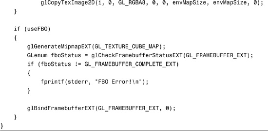
Notice the glCopyTexImage2D call in the listing, which we can avoid entirely when FBOs are enabled. That’s six copies we’re avoiding every time we regenerate the environment map. And because objects in the scene are moving every frame, our environment map has to be regenerated with every frame, too. Also notice the call to glGenerateMipmapEXT, which semiautomatically generates the mipmap chain. Using mipmapping significantly improves image quality by reducing aliasing. See the resulting image in Figure 18.5.
Figure 18.5. Dynamic environment mapping benefits from FBOs. (This figure also appears in the Color insert.)

Multiple Render Targets
To demonstrate the capability to render to multiple color buffers simultaneously, we’ll render our scene to an FBO-attached texture, then run that texture through a fragment shader that applies four different image transformations simultaneously: edge detection, color inversion, blur, and grayscale. See Listing 18.4.
Listing 18.4. A GLSL Fragment Shader Outputting Four Different Colors

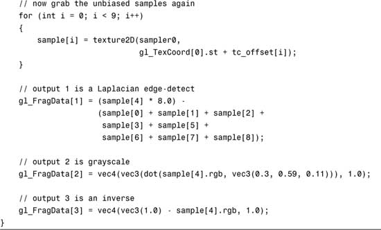
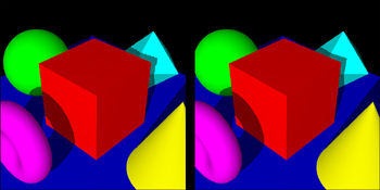
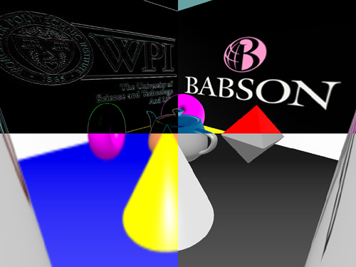
The four color outputs from the fragment shader are mapped to an FBO with four color attachments, again textures. The four textures with four different framebuffer effects are then tiled in a final pass to the window after unbinding the FBO. See Listing 18.5 for the relevant FBO setup code, and Figure 18.6 for the end result.
Listing 18.5. Set Up Two FBOs with Different Attachments
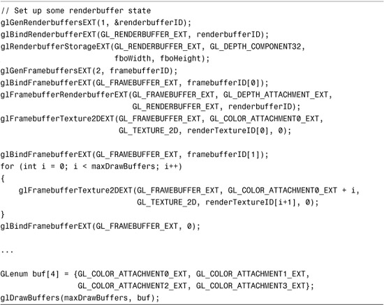
Figure 18.6. These four postprocessing effects were generated in parallel, saving three extra passes! (This figure also appears in the Color insert.)
Floating-Point Textures
The GL_ARB_texture_float extension makes available 12 new internal formats for textures, each of the six base color formats in both 16-bit and 32-bit floating-point flavors:

For nonfloat internal formats, when you call glTexImage* with an integer data type (e.g., GL_UNSIGNED_BYTE), the values are normalized to the range [0,1]. GL_FLOAT type data passed in for use with a nonfloat internal format gets clamped to [0,1]. With the new floating-point internal formats, no normalization or clamping takes place. What you specify is what will be stored, and with the precision and range associated with your choice of 16-bit or 32-bit floats.
Older-generation hardware may not have full support for some functionality when used in conjunction with floating-point textures, such as mipmapping or wrap modes that might sample from the border color (e.g., GL_CLAMP and GL_CLAMP_TO_BORDER). When targeting older hardware, you may witness unexpected rendering or the rendering may be emulated in software with abysmal performance. Beware!
Not only can you render from textures with these new formats, but courtesy of FBO’s render-to-texture capabilities, you can also attach floating-point textures to an FBO and render to them. In fact, even renderbuffers can have floating-point internal formats. However, due to implementation-dependent restrictions, always remember to check the completeness of your FBOs with glCheckFramebufferStatusEXT before assuming that anything will work!
Note that there is also an extension, GL_ARB_color_buffer_float, that in coordination with window system-specific extensions (WGL_ARB_pixel_format_float and GLX_ARB_fbconfig_float) allow floating-point rendering directly to the window’s framebuffer. However, FBOs cover 99% of interesting cases and are easier to use and more portable. That’s probably why the GL_ARB_texture_float extension is the one most widely adopted, and the one we’ll be using here.
High Dynamic Range
Now that we have floating-point textures, what are we going to use them for? The short answer is anything you want. No longer limited to capturing 256 shades of colors between 0.0 and 1.0, you can put any arbitrary data into these floating-point buffers.
This high-precision data combined with shader programmability is ushering in a new trend in computing called GPGPU (General-Purpose Graphics Processing Units). Essentially, you can use your GPU as a generic math coprocessor! Considering that some users have a GPU more powerful (and expensive) than their CPU, it would be a shame to tap into it only when drawing pretty pictures on the screen.
Since pretty pictures are our specialty, let’s look at an application of floating-point textures that falls into that category: High Dynamic Range (HDR). Take a quick look around. Maybe you have a light bulb in sight. Look out the window, and perhaps you’ll see the sun or the moon. (I apologize to those readers outside the Earth’s solar system—you’ll have to bear with me.) Each light source on its own looks bright. But they’re not all equally bright, are they? Staring at a light bulb may leave temporary marks on your retina, but staring at the sun could blind you. Don’t try this, just take my word for it.
You might want to model a 60-watt light bulb in your virtual scene. What color do you assign it? Well, it’s totally bright white, so that would be (1,1,1,1), right? Now you’re in a bit of a pickle when you want to add a 120-watt light bulb, or the sun, which might be approximated by a 1000-watt light bulb. Something can be white, but there’s always something brighter white. (To quote the wisdom of Nigel Tufnel in This Is Spinal Tap, “These go to eleven.”)
In the realm of HDR, we want to remove the artificial limits in which colors are always represented in the range [0,1]. We can work with them as floating-point values with dynamic ranges as high as +/– 3.4×1038. Since there is no common display hardware capable of outputting such a high range (film comes only slightly closer than CRTs or LCDs), this representation will only help us while making intermediate calculations. Eventually we’ll have to map back into the [0,1] low dynamic range, but only when we’re ready.
OpenEXR File Format
Industrial Light and Magic has made our demonstration of floating-point textures easier by creating an open standard format for storing HDR images. They also make available open-source sample code for working with the format. And to top it off, they provide a number of interesting sample images that we’re free to use as we please.
Incorporating the code for loading images was a breeze, as evident in Listing 18.6.
Listing 18.6. Loading OpenEXR Images into Floating-Point Textures


We create an RGBAInputFile instance, passing in a string with the path to the EXR file. We check the image’s width and height via RGBAInputFile::dataWindow, and then establish an Array2D<Rgba> of RGBA pixels of the appropriate size via Array2D::resizeErase. We extract the texels from the file by first pointing at our array via RGBAInputFile::setFrameBuffer and then kicking off the transfer via RGBAInputFile::readPixels. So far this has all been performed using the OpenEXR library.
To dump the data into the OpenGL driver, we first ensure that the texture isn’t too big to be supported. Also, we may need to bump up our texture size to the next power-of-two in case the underlying OpenGL implementation doesn’t handle NPOT textures. In this case, we’ll just frame the texture with black. Then we signal the aspect ratio elsewhere so that the proper viewport and mouse mapping can be established. Finally, we make the OpenGL calls to send in our texels to be stored as 16-bit floats with GL_RGB16F_ARB.
Tone Mapping
We have one final hurdle to cross. We need to map our high dynamic range floating-point data back to the range [0,1], which will then be displayed on a low dynamic range computer display. Doing this range reduction, while attempting to maintain important visual characteristics, is known as tone mapping. One very simple way of tone mapping is to simply clamp any value greater than 1.0. In other circles, this is known as saturating or clipping a color. It’s a bit of a cop-out, but for educational purposes it’s useful to look at the results of this. See Listing 18.7 and Figure 18.7, where we lose all detail in the bright portions of the image, which become a uniform white.
Listing 18.7. This Tone Mapping Shader Drops the Ball and Just Clamps
// clamped.fs
//
// No tone mapping: clamp [0,oo) -> [0,1]
uniform sampler2D sampler0;
void main(void)
{
vec4 sample = texture2D(sampler0,
gl_TexCoord[0].st);
// clamp color
gl_FragColor.rgb = clamp(sample.rgb, 0.0, 1.0);
gl_FragColor.a = 1.0;
}
Figure 18.7. Clamping does not make for good tone mapping!

A very simple but often adequate tone mapping technique manages to map the entire range of positive floats down to the range [0,1] using the equation X = Y/(Y+1). Right off the bat, values of 1.0 get cut in half to 0.5. But you can be assured that no matter how bright your scene gets, there will always be a home for every wattage of light bulb, as it were. See Listing 18.8 and Figure 18.8, where suddenly the details in the bright regions pop out.
Listing 18.8. General-Purpose Tone Mapping Shader
// trival.fs
//
// Trivial tone mapping: map [0,oo) -> [0,1)
uniform sampler2D sampler0;
void main(void)
{
vec4 sample = texture2D(sampler0,
gl_TexCoord[0].st);
// invert color components
gl_FragColor.rgb = sample.rgb / (sample.rgb + 1.0);
gl_FragColor.a = 1.0;
}
Figure 18.8. Every brightness level gets mapped now, but those that used to be in the range [0,1] have been further diminished.
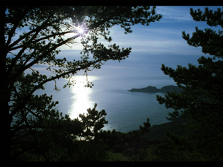
If you go into a movie theatre after being in the bright sun, you’ll see a whole lot of black. But over time, you’ll start to be able to make out details in your surroundings. Believe it or not, pirates wore a patch over one eye not because of disfigurement or fashion trends, but so that one eye would always be sensitive in darkness, for example, when going below deck on a sunny day. To pick out detail in the extra bright areas or extra dark areas of an HDR image, we can use a tone mapping method that works sort of like our eyes do. Using the cursor to choose which part of the image our eyes are accustomed to, we’ll take the local maximum brightness from that area and scale it down to 1.0. See Listing 18.9 and Figure 18.9.
Listing 18.9. Custom Auto-Exposure Tone Mapping
// iris.fs
//
// Iris tone mapping: map [0,max] -> [0,1]
// for a local maximum "max" set externally
uniform sampler2D sampler0;
uniform vec3 max;
void main(void)
{
vec4 sample = texture2D(sampler0,
gl_TexCoord[0].st);
// scale all color channels evenly
float maxMax = (max.r > max.g) ? max.r : max.g;
maxMax = (maxMax > max.b) ? maxMax : max.b;
gl_FragColor.rgb = sample.rgb / maxMax;
gl_FragColor.a = 1.0;
}
Figure 18.9. Who knew there was this much detail in the foreground trees?

One last variation of the tone mapping implemented for the floating-point textures sample scales each color channel independently, no longer maintaining the original hue. This is not unlike white balancing. In the color insert (Color Plate 29), you can see how it turns an otherwise warm orange candle glow into true white. Cameras often perform this function to compensate for the discoloration caused by artificial lighting.
There are more complex methods of compressing HDR images so that details in both the lightest and the darkest regions are presented simultaneously. I encourage you to pursue HDR compression further if you’re interested.
Making Your Whites Whiter and Your Brights Brighter
Sorry, Clorox. I couldn’t resist. For our last sample, I’ll show how to make good old (1,1,1,1) white look brighter than ever using a bloom effect. This gives the appearance of film overexposure with saturated surfaces bleeding past their edges. If you’ve played any recent games with the eye candy cranked up, you probably know what I’m talking about.
Even if you don’t have support for floating-point textures, you can still take advantage of the bloom effect. It may look a little muted because bright areas will quickly lose their brightness as they’re blurred. But you may find second-rate bloom to be better than no bloom at all, so give it a try.
Drawing the Scene
In the first pass, we draw our scene. We’ll borrow the toy ball procedural texture shader from Chapter 17, “Fragment Shading: Empower Your Pixel Processing.” This time, however, instead of painting the star with a red diffuse material color, we will make the star emit a red glow. The intensity of the glow will be based on how quickly the ball is spinning. See Listing 18.10. Figure 18.10 illustrates the result of this first pass.
Listing 18.10. Toy Ball Makes a Reappearance Now with a Healthy Glow
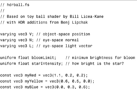

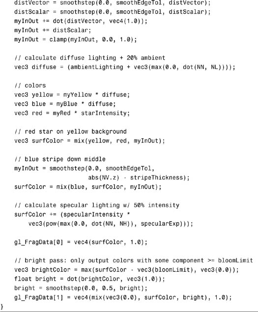
Figure 18.10. Our glowing toy ball after the first pass. The red tinted glow appears white due to floating-point clamping because all color channels exceed 1.0.

One important difference between this new version of the toy ball and the old one is the calculation of the red star color, which is no longer dependent on the lighting equation. Instead, it is multiplied by an externally set uniform, starIntensity. The other key difference is that it’s outputting two colors to the gl_FragData array. More on that next.
Bright Pass
While rendering the entire toy ball during the first pass, we’ll also render a modified version to a second FBO color attachment. This version will contain only the brightest parts of the scene, those brighter than 1.0. (This threshold is adjustable via the bloomLimit uniform in the shader.) All dimmer parts of the scene are drawn black. We use the smoothstep built-in function so there’s a gentle transition from bright to black. See Figure 18.11 for a look at the intermediate results from the bright pass.
Figure 18.11. The bright pass will be the foundation for our bloom generation.

Gaussian Blur with a Little Help
Bloom needs some serious blurring to achieve a decent effect. We’ll use a 5×5 kernel, which already pushes the limits of interactivity, especially on older hardware. So how can we get a more bountiful blur than this? The answer lies in some filtering that is always at our fingertips: mipmap generation.
By calling glGenerateMipmapsEXT on the FBO-attached texture containing the bright pass results, we get access to an array of images, each of which is more blurred than the last courtesy of downsampling, as shown in Figure 18.12. It isn’t a beautiful Gaussian blur, but after we apply our 5×5 kernel in Listing 18.11, the results are quite nice, as shown in Figure 18.13. We apply the blur filter to the first four levels of the texture by setting both GL_TEXTURE_BASE_LEVEL and GL_TEXTURE_MAX_LEVEL to 0, then 1, then 2, and finally 3.
Figure 18.12. The bright pass is progressively downsampled.

Listing 18.11. 5×5 Gaussian Blur Kernel
// gaussian.fs
//
// gaussian 5x5 kernel
uniform sampler2D sampler0;
uniform vec2 tc_offset[25];
void main(void)
{
vec4 sample[25];
for (int i = 0; i < 25; i++)
{
sample[i] = texture2D(sampler0,
gl_TexCoord[0].st + tc_offset[i]);
}
// 1 4 7 4 1
// 4 16 26 16 4
// 7 26 41 26 7 / 273
// 4 16 26 16 4
// 1 4 7 4 1
gl_FragColor =
((1.0 * (sample[0] + sample[4] + sample[20] + sample[24])) +
(4.0 * (sample[1] + sample[3] + sample[5] + sample[9] +
sample[15] + sample[19] + sample[21] + sample[23])) +
(7.0 * (sample[2] + sample[10] + sample[14] + sample[22])) +
(16.0 * (sample[6] + sample[8] + sample[16] + sample[18])) +
(26.0 * (sample[7] + sample[11] + sample[13] + sample[17])) +
(41.0 * sample[12])
) / 273.0;
}
Figure 18.13. The downsampled levels are now blurred.

Notice the red halo around the bloom most evident with the coarsest blur. This is a pleasant side effect of the blurring. Remember that the original star color is tinted red. Whereas in the middle of the bloom the colors are too bright to escape pure saturated whiteness, at the fringes where they are mixed with dimmer colors, the true redness of the glow has a chance to come through.
The Sum Is Greater Than Its Parts
All that’s left is to add everything up in the window’s framebuffer. We have the original scene and four levels worth of blur. This is not a difficult step. Figure 18.14 shows the results of Listing 18.12.
Figure 18.14. Our toy ball is finally in full bloom.

Listing 18.12. Math Is Hard, Especially Addition
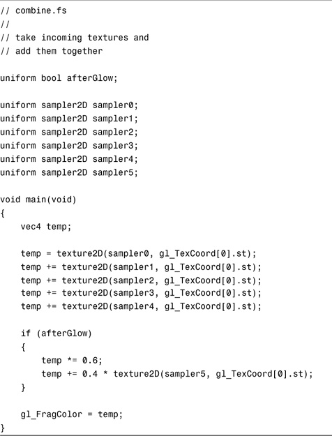
PBOs Make a Comeback
What’s that last texture we’re blending into the final frame? Afterglow is just a ghost image simulating retinal burn-in. This is reminiscent of our first PBO sample, and again we’ll use a PBO to read back the window’s framebuffer contents and send it back in as a texture, all without touching client memory. See Color Plate 30 in the color insert for the final toy ball image with both bloom and afterglow.
This could also be achieved by rendering the last pass to an FBO, saving the attached texture for use as the next frame’s afterglow, and then adding one more pass to get the result into the window. Or you could use a simple call to glCopyTexImage. But then we wouldn’t be able to exercise our new friend, the PBO. Where’s the fun in that?
Summary
PBOs, FBOs, and floating-point textures, when teamed up with shader programmability, open up a universe of possibilities. Squeezing this much potential into one chapter is certainly overambitious. I hope you at least have a sense for the immense GPU power at your disposal. Please go forth and use this power for good, not evil.