Chapter 30. Implementing IPv6 Addressing on Routers
This chapter covers the following exam topics:
1.0 Network Fundamentals
1.12 Configure, verify, and troubleshoot IPv6 addressing
1.13 Configure and verify IPv6 Stateless Address Auto Configuration
1.14 Compare and contrast IPv6 address types
1.14.a Global unicast
1.14.b Unique local
1.14.c Link local
1.14.d Multicast
1.14.e Modified EUI 64
1.14.f Autoconfiguration
1.14.g Anycast
With IPv4 addressing, some devices, like servers and routers, typically use static predefined IPv4 addresses. End-user devices do not mind if their address changes from time to time, and they typically learn an IPv4 address dynamically using DHCP. IPv6 uses the same general mode, with servers, routers, and other devices in the control of the IT group often using predefined IPv6 addresses, and with end-user devices using dynamically learned IPv6 addresses.
This chapter focuses on the addresses configured on routers, while Chapter 31, “Implementing IPv6 Addressing on Hosts,” focuses on the addresses learned by IPv6 hosts.
Routers require unicast IPv6 addresses on their interfaces. At the same time, routers use a variety of other IPv6 addresses to participate in many of the protocols and roles required of a router. This chapter begins with the more obvious IPv6 addressing configuration, with features that mirror IPv4 features, showing how to configure interfaces with IPv6 addresses and view that configuration with show commands. The second half of the chapter introduces new IPv6 addressing concepts, showing some other addresses used by routers when doing different tasks.
“Do I Know This Already?” Quiz
Take the quiz (either here, or use the PTP software) if you want to use the score to help you decide how much time to spend on this chapter. The answers are at the bottom of the page following the quiz, and the explanations are in DVD Appendix C and in the PTP software.

1. Router R1 has an interface named Gigabit Ethernet 0/1, whose MAC address has been set to 0200.0001.000A. Which of the following commands, added in R1’s Gigabit Ethernet 0/1 configuration mode, gives this router’s G0/1 interface a unicast IPv6 address of 2001:1:1:1:1:200:1:A, with a /64 prefix length?
a. ipv6 address 2001:1:1:1:1:200:1:A/64
b. ipv6 address 2001:1:1:1:1:200:1:A/64 eui-64
c. ipv6 address 2001:1:1:1:1:200:1:A /64 eui-64
d. ipv6 address 2001:1:1:1:1:200:1:A /64
e. None of the other answers are correct.
2. Router R1 has an interface named Gigabit Ethernet 0/1, whose MAC address has been set to 5055.4444.3333. This interface has been configured with the ipv6 address 2000:1:1:1::/64 eui-64 subcommand. What unicast address will this interface use?
a. 2000:1:1:1:52FF:FE55:4444:3333
b. 2000:1:1:1:5255:44FF:FE44:3333
c. 2000:1:1:1:5255:4444:33FF:FE33
d. 2000:1:1:1:200:FF:FE00:0
3. Router R1 currently supports IPv4, routing packets in and out all its interfaces. R1’s configuration needs to be migrated to support dual-stack operation, routing both IPv4 and IPv6. Which of the following tasks must be performed before the router can also support routing IPv6 packets? (Choose two answers.)
a. Enable IPv6 on each interface using an ipv6 address interface subcommand.
b. Enable support for both versions with the ip versions 4 6 global command.
c. Additionally enable IPv6 routing using the ipv6 unicast-routing global command.
d. Migrate to dual-stack routing using the ip routing dual-stack global command.
4. Router R1 has an interface named Gigabit Ethernet 0/1, whose MAC address has been set to 0200.0001.000A. The interface is then configured with the ipv6 address 2001:1:1:1:200:FF:FE01:B/64 interface subcommand; no other ipv6 address commands are configured on the interface. Which of the following answers lists the link local address used on the interface?
a. FE80::FF:FE01:A
b. FE80::FF:FE01:B
c. FE80::200:FF:FE01:A
d. FE80::200:FF:FE01:B
5. Which of the following multicast addresses is defined as the address for sending packets to only the IPv6 routers on the local link?
a. FF02::1
b. FF02::2
c. FF02::5
d. FF02::A
Answers to the “Do I Know This Already?” quiz:
Foundation Topics
Implementing Unicast IPv6 Addresses on Routers
Every company bases its enterprise network on one or more protocol models, or protocol stacks. In the earlier days of networking, enterprise networks used one or more protocol stacks from different vendors, as shown on the left of Figure 30-1. Over time, companies added TCP/IP (based on IPv4) to the mix. Eventually, companies migrated fully to TCP/IP as the only protocol stack in use.

The emergence of IPv6 requires that IPv6 be implemented in end-user hosts, servers, routers, and other devices. However, corporations cannot just migrate all devices from IPv4 to IPv6 over one weekend. Instead, what will likely occur is some kind of long-term migration and coexistence, in which for a large number of years, most corporate networks again use multiple protocol stacks: one based on IPv4 and one based on IPv6.
Eventually, over time, we might all see the day when enterprise networks run only IPv6, without any IPv4 remaining, but that day might take awhile. Figure 30-2 shows the progression, just to make the point, but who knows how long it will take?


One way to add IPv6 support to an established IPv4-based enterprise internetwork is to implement a dual-stack strategy. To do so, the routers can be configured to route IPv6 packets, with IPv6 addresses on their interfaces, with a similar model to how routers support IPv4. Then hosts can implement IPv6 when ready, running both IPv4 and IPv6 (dual stacks). The first major section of this chapter shows how to configure and verify unicast IPv6 addresses on routers.
Static Unicast Address Configuration
Cisco routers give us two options for static configuration of IPv6 addresses. In one case, you configure the full 128-bit address, while in the other, you configure a 64-bit prefix and let the router derive the second half of the address (the interface ID). The next few pages show how to configure both options and how the router chooses the second half of the IPv6 address.
Configuring the Full 128-Bit Address
To statically configure the full 128-bit unicast address—either global unicast or unique local—the router needs an ipv6 address address/prefix-length interface subcommand on each interface. The address can be an abbreviated IPv6 address or the full 32-digit hex address. The command includes the prefix length value, at the end, with no space between the address and prefix length.
The configuration of the router interface IPv6 address really is that simple. Figure 30-3, along with Examples 30-1 and 30-2, shows a basic example. The figure shows the global unicast IPv6 address used by two different routers, on two interfaces each. As usual, all subnets use a /64 prefix length.

Example 30-1 Configuring Static IPv6 Addresses on R1
ipv6 unicast-routing
!
interface GigabitEthernet0/0
ipv6 address 2001:DB8:1111:1::1/64
!
interface Serial0/0/0
ipv6 address 2001:0db8:1111:0002:0000:0000:0000:0001/64
Example 30-2 Configuring Static IPv6 Addresses on R2
ipv6 unicast-routing
!
interface GigabitEthernet0/0
ipv6 address 2001:DB8:1111:3::2/64
!
interface Serial0/0/1
ipv6 address 2001:db8:1111:2::2/64
Note
The configuration on R1 in Example 30-1 uses both abbreviated and unabbreviated addresses, and both lowercase and uppercase hex digits, showing that all are allowed. Router show commands list the abbreviated value with uppercase hex digits.
Enabling IPv6 Routing
While the configurations shown in Examples 30-1 and 30-2 focus on the IPv6 address configuration, they also include an important but often overlooked step when configuring IPv6 on Cisco routers: IPv6 routing needs to be enabled.
Before routers can route (forward) IPv6 packets, IPv6 routing must be enabled. On Cisco routers, IPv4 routing is enabled by default, but IPv6 routing is not enabled by default. The solution takes only a single command—ipv6 unicast-routing—which enables IPv6 routing on the router.
Note that a router must enable IPv6 globally (ipv6 unicast-routing) and enable IPv6 on the interface (ipv6 address) before the router will attempt to route packets in and out an interface. (If the router happens to omit the ipv6 unicast-routing command, it can still be configured with interface IPv6 addresses, but the router acts like an IPv6 host and does not route IPv6 packets.)
Verifying the IPv6 Address Configuration
IPv6 uses many show commands that mimic the syntax of IPv4 show commands. For example:
![]() The show ipv6 interface brief command gives you interface IPv6 address info, but not prefix length info, similar to the IPv4 show ip interface brief command.
The show ipv6 interface brief command gives you interface IPv6 address info, but not prefix length info, similar to the IPv4 show ip interface brief command.
![]() The show ipv6 interface command gives the details of IPv6 interface settings, much like the show ip interface command does for IPv4.
The show ipv6 interface command gives the details of IPv6 interface settings, much like the show ip interface command does for IPv4.
The one notable difference in the most common commands is that the show interfaces command still lists the IPv4 address and mask but tells us nothing about IPv6. So, to see IPv6 interface addresses, use commands that begin with show ipv6. Example 30-3 lists a few samples from Router R1, with the explanations following.
Example 30-3 Verifying Static IPv6 Addresses on Router R1
! The first interface is in subnet 1
R1# show ipv6 interface GigabitEthernet 0/0
GigabitEthernet0/0 is up, line protocol is up
IPv6 is enabled, link-local address is FE80::1FF:FE01:101
No Virtual link-local address(es):
Description: LAN at Site 1
Global unicast address(es):
2001:DB8:1111:1::1, subnet is 2001:DB8:1111:1::/64
Joined group address(es):
FF02::1
FF02::2
FF02::A
FF02::1:FF00:1
FF02::1:FF01:101
MTU is 1500 bytes
ICMP error messages limited to one every 100 milliseconds
ICMP redirects are enabled
ICMP unreachables are sent
ND DAD is enabled, number of DAD attempts: 1
ND reachable time is 30000 milliseconds (using 30000)
ND advertised reachable time is 0 (unspecified)
ND advertised retransmit interval is 0 (unspecified)
ND router advertisements are sent every 200 seconds
ND router advertisements live for 1800 seconds
ND advertised default router preference is Medium
Hosts use stateless autoconfig for addresses.
R1# show ipv6 interface S0/0/0
Serial0/0/0 is up, line protocol is up
IPv6 is enabled, link-local address is FE80::1FF:FE01:101
No Virtual link-local address(es):
Description: link to R2
Global unicast address(es):
2001:DB8:1111:2::1, subnet is 2001:DB8:1111:2::/64
Joined group address(es):
FF02::1
FF02::2
FF02::A
FF02::1:FF00:1
FF02::1:FF01:101
MTU is 1500 bytes
! Lines omitted for brevity
R1# show ipv6 interface brief
GigabitEthernet0/0 [up/up]
FE80::1FF:FE01:101
2001:DB8:1111:1::1
GigabitEthernet0/1 [administratively down/down]
unassigned
Serial0/0/0 [up/up]
FE80::1FF:FE01:101
2001:DB8:1111:2::1
Serial0/0/1 [administratively down/down]
unassigned
First, focus on the output of the two show ipv6 interface commands that make up most of the output in Example 30-3. The first command lists interface G0/0, showing output about that interface only. Note that the output lists the configured IPv6 address and prefix length, as well as the IPv6 subnet (2001:DB8:1111:1::/64), which the router calculated based on the IPv6 address. The second show ipv6 interface command shows similar details for interface S0/0/0, with some of the volume of output omitted.
The end of the example lists the output of the show ipv6 interface brief command. Similar to the IPv4-focused show ip interface brief command, this command lists IPv6 addresses, but not the prefix length or prefixes. This command also lists all interfaces on the router, whether or not IPv6 is enabled on the interfaces. For example, in this case, the only two interfaces on R1 that have an IPv6 address are G0/0 and S0/0/0, as configured earlier in Example 30-1.
Beyond the IPv6 addresses on the interfaces, the router also adds IPv6 connected routes to the IPv6 routing table off each interface. Just as with IPv4, the router keeps these connected routes in the IPv6 routing table only when the interface is in a working (up/up) state. But if the interface has an IPv6 unicast address configured, and the interface is working, the router adds the connected routes. Example 30-4 shows the connected IPv6 on Router R1 from Figure 30-3.
Example 30-4 Displaying Connected IPv6 Routes on Router R1
R1# show ipv6 route connected
IPv6 Routing Table - default - 5 entries
Codes: C - Connected, L - Local, S - Static, U - Per-user Static route
B - BGP, R - RIP, I1 - ISIS L1, I2 - ISIS L2
IA - ISIS interarea, IS - ISIS summary, D - EIGRP, EX - EIGRP external
ND - ND Default, NDp - ND Prefix, DCE - Destination, NDr - Redirect
O - OSPF Intra, OI - OSPF Inter, OE1 - OSPF ext 1, OE2 - OSPF ext 2
ON1 - OSPF NSSA ext 1, ON2 - OSPF NSSA ext 2
C 2001:DB8:1111:1::/64 [0/0]
via GigabitEthernet0/0, directly connected
C 2001:DB8:1111:2::/64 [0/0]
via Serial0/0/0, directly connected
Generating a Unique Interface ID Using Modified EUI-64
IPv6 follows the same general model as IPv4 regarding which types of devices typically use static, predefined addresses and which use dynamically learned address. For example, routers inside an enterprise use static IPv4 addresses, while end-user devices typically learn their IPv4 address using DHCP. With IPv6, routers also typically use static IPv6 addresses, while user devices use DHCP or Stateless Address Auto Configuration (SLAAC) to dynamically learn their IPv6 address.
Interestingly, routers have two options for configuring a stable and predictable IPv6 interface address that does not change. One method, discussed already in this chapter, uses the ipv6 address command to define the entire 128-bit address, as shown in Examples 30-1 and 30-2. The other method uses this same ipv6 address command to configure only the 64-bit IPv6 prefix for the interface and lets the router automatically generate a unique interface ID.
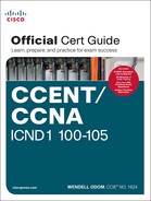
This second method uses rules called modified EUI-64 (extended unique identifier). Often, in the context of IPv6 addressing, people refer to modified EUI-64 as just EUI-64; there is no other term or concept about EUI-64 that you need to know for IPv6. The configuration that uses EUI-64 includes a keyword to tell the router to use EUI-64 rules, along with the 64-bit prefix. The router then uses EUI-64 rules to create the interface ID part of the address, as follows:
1. Split the 6-byte (12-hex-digit) MAC address in two halves (6 hex digits each).
2. Insert FFFE in between the two, making the interface ID now have a total of 16 hex digits (64 bits).
3. Invert the seventh bit of the interface ID.
Figure 30-4 shows the major pieces of how the address is formed.
Although this process might seem a bit convoluted, it works. Also, with a little practice, you can look at an IPv6 address and quickly notice the FFFE in the middle of the interface ID and then easily find the two halves of the corresponding interface’s MAC address. But you need to be ready to do the same math, in this case to predict the EUI-64 formatted IPv6 address on an interface.
For example, if you ignore the final step of inverting the seventh bit, the rest of the steps just require that you move the pieces around. Figure 30-5 shows two examples, just so you see the process.

Both examples follow the same process. Each starts with the MAC address, breaking it into two halves (Step 2). The third step inserts FFFE in the middle, and the fourth step inserts a colon every four hex digits, keeping with IPv6 conventions.
While the examples in Figure 30-5 show most of the steps, they omit the final step. The final step requires that you convert the first byte (first two hex digits) from hex to binary, invert the seventh of the 8 bits, and convert the bits back to hex. Inverting a bit means that if the bit is a 0, make it a 1; if it is a 1, make it a 0. Most of the time, with IPv6 addresses, the original bit will be 0 and will be inverted to a 1.
For example, Figure 30-6 completes the two examples from Figure 30-5, focusing only on the first two hex digits. The examples show each pair of hex digits (Step 1) and the binary equivalent (Step 2). Step 3 shows a copy of those same 8 bits, except the seventh bit is inverted; the example on the left inverts from 0 to 1, and the example on the right inverts from 1 to 0. Finally, the bits are converted back to hex at Step 4.

If you do not remember how to do hex to binary conversions, take a few moments to review the process. If you memorize the 16 hex values for digits 0 through F, with the corresponding binary values, the conversion can be easy. If you do not have those handy in your memory, take a few moments to look at Table A-2 in Appendix A, “Numeric Reference Tables.”
For those of you who prefer the decimal shortcuts, with a little memorization you can do the bit-flip math without doing any hex-binary conversions. First, note that the process to invert the seventh bit, when working with a hexadecimal IPv6 address, flips the third of 4 bits in a single hex digit. With only 16 single hex digits, you could memorize what each hex digit becomes if its third bit is inverted, and you can easily memorize those values with a visual process.
If you want to try to memorize the values, it helps to work through the following process a few times, so grab a piece of scratch paper. Then write the 16 single hex digits as shown on the left side of Figure 30-7. That is, write them in eight rows of two numbers each, with the spacing as directed in the figure.

Next, start at the top of the lists, and draw arrow lines between two numbers in the same column on the top left (0 and 2). Then move down the left-side column, connecting the next two digits (4 and 6) with an arrow line, then 8 and A, and then C and E. Repeat the process on the right, re-creating the right side of Figure 30-7.
The figure you drew (and the right side of Figure 30-7) shows the hex digits which, when you invert their third bit, converts to the other. That is, 0 converts to 2; 2 converts to 0; 1 converts to 3; 3 converts to 1; 4 converts to 6; 6 converts to 4; and so on. So, on the exam, if you can remember the pattern to redraw Figure 30-7, you could avoid doing binary/hexadecimal conversion. Use whichever approach makes you more comfortable.
As usual, the best way to get comfortable with forming these EUI-64 interface IDs is to calculate some yourself. Table 30-2 lists some practice problems, with an IPv6 64-bit prefix in the first column and the MAC address in the second column. Your job is to calculate the full (unabbreviated) IPv6 address using EUI-64 rules. The answers are at the end of the chapter, in the section “Answers to Earlier Practice Problems.”

Configuring a router interface to use the EUI-64 format uses the ipv6 address address/prefix-length eui-64 interface subcommand. The eui-64 keyword tells the router to find the interface MAC address and do the EUI-64 conversion math to find the interface ID.
Example 30-5 shows a revised configuration on Router R1, as compared to the earlier Example 30-1. In this case, R1 uses EUI-64 formatting for its IPv6 addresses.
Example 30-5 Configuring R1’s IPv6 Interfaces Using EUI-64
ipv6 unicast-routing
!
! The ipv6 address command now lists a prefix, not the full address
interface GigabitEthernet0/0
ipv6 address 2001:DB8:1111:1::/64 eui-64
!
interface Serial0/0/0
ipv6 address 2001:DB8:1111:2::/64 eui-64
R1# show ipv6 interface brief
GigabitEthernet0/0 [up/up]
FE80::1FF:FE01:101
2001:DB8:1111:1:0:1FF:FE01:101
GigabitEthernet0/1 [administratively down/down]
unassigned
Serial0/0/0 [up/up]
FE80::1FF:FE01:101
2001:DB8:1111:2:0:1FF:FE01:101
Serial0/0/1 [administratively down/down]
unassigned
Note that the example shows EUI-64 being used on a serial interface, which does not have an associated MAC address. For interfaces that do not have a MAC address, the router chooses the MAC of the lowest-numbered router interface that does have a MAC. In this example, R1 uses its G0/0 interface MAC to form the EUI-64 interface ID for all the serial interfaces.
When you use EUI-64, the address value in the ipv6 address command should be the prefix, not the full 128-bit IPv6 address. However, if you mistakenly type the full address and still use the eui-64 keyword, IOS accepts the command and converts the address to the matching prefix before putting the command into the running config file. For example, IOS converts ipv6 address 2000:1:1:1::1/64 eui-64 to ipv6 address 2000:1:1:1::/64 eui-64.
Dynamic Unicast Address Configuration
In most cases, network engineers will configure the IPv6 addresses of router interfaces so that the addresses do not change until the engineer changes the router configuration. However, routers can be configured to use dynamically learned IPv6 addresses. These can be useful for routers connecting to the Internet through some types of Internet access technologies, like DSL and cable modems.
Cisco routers support two ways for the router interface to dynamically learn an IPv6 address to use:
![]() Stateful DHCP
Stateful DHCP
![]() Stateless Address Autoconfiguration (SLAAC)
Stateless Address Autoconfiguration (SLAAC)
Both methods use the familiar ipv6 address command. Of course, neither option configures the actual IPv6 address; instead, the commands configure a keyword that tells the router which method to use to learn its IPv6 address. Example 30-6 shows the configuration, with one interface using stateful DHCP and one using SLAAC.
Example 30-6 Router Configuration to Learn IPv6 Addresses with DHCP and SLAAC
! This interface uses DHCP to learn its IPv6 address
interface FastEthernet0/0
ipv6 address dhcp
!
! This interface uses SLAAC to learn its IPv6 address
interface FastEthernet0/1
ipv6 address autoconfig
Cisco routers also have to be ready to play a role with DHCP and SLAAC on behalf of other IPv6 devices in the network. Chapter 31, which focuses on implementing IPv6 on hosts, discusses the protocols and the responsibilities of the routers.
Special Addresses Used by Routers
IPv6 configuration on a router begins with the simple steps discussed in the first part of this chapter. After you configure the ipv6 unicast-routing global configuration command, to enable the function of IPv6 routing, the addition of a unicast IPv6 address on an interface causes the router to do the following:
![]() Gives the interface a unicast IPv6 address
Gives the interface a unicast IPv6 address
![]() Enables the routing of IPv6 packets in/out that interface
Enables the routing of IPv6 packets in/out that interface
![]() Defines the IPv6 prefix (subnet) that exists off that interface
Defines the IPv6 prefix (subnet) that exists off that interface
![]() Tells the router to add a connected IPv6 route for that prefix, to the IPv6 routing table, when that interface is up/up
Tells the router to add a connected IPv6 route for that prefix, to the IPv6 routing table, when that interface is up/up
In fact, if you pause and look at the list again, the same ideas happen for IPv4 when you configure an IPv4 address on a router interface.
While all the IPv6 features in this list work much like similar features in IPv4, IPv6 also has a number of additional functions not seen in IPv4. Often, these additional functions use other IPv6 addresses, many of which are multicast addresses. This second major section of the chapter examines the additional IPv6 addresses seen on routers, with a brief description of how they are used.
Link-Local Addresses
IPv6 uses link-local addresses as a special kind of unicast IPv6 address. These addresses are not used for normal IPv6 packet flows that contain data for applications. Instead, these addresses are used by some overhead protocols and for routing. This next topic first looks at how IPv6 uses link-local addresses and then how routers create link-local addresses.
Link-Local Address Concepts
Each IPv6 host (routers included) uses an additional unicast address called a link-local address. Packets sent to a link-local address do not leave the IPv6 subnet because routers do not forward packets sent to a link-local address.
IPv6 uses link-local addresses for a variety of protocols. Many IPv6 protocols that need to send messages inside a single subnet typically use link-local addresses, rather than the host’s global unicast or unique local address. For example, Neighbor Discovery Protocol (NDP), which replaces the functions of IPv4’s ARP, uses link-local addresses.
Routers also use link-local addresses as the next-hop IP addresses in IPv6 routes, as shown in Figure 30-8. IPv6 hosts also use a default router (default gateway) concept, like IPv4, but instead of the router address being in the same subnet, hosts refer to the router’s link-local address. The show ipv6 route command lists the link-local address of the neighboring router, and not the global unicast or unique local unicast address.

Following are some key facts about link-local addresses:
Unicast (not multicast): Link-local addresses represent a single host, and packets sent to a link-local address should be processed by only that one IPv6 host.
Forwarding scope is the local link only: Packets sent to a link-local address do not leave the local data link because routers do not forward packets with link-local destination addresses.
Automatically generated: Every IPv6 host interface (and router interface) can create its own link-local address automatically, solving some initialization problems for hosts before they learn a dynamically learned global unicast address.
Common uses: Link-local addresses are used for some overhead protocols that stay local to one subnet and as the next-hop address for IPv6 routes.
Creating Link-Local Addresses on Routers
IPv6 hosts and routers can calculate their own link-local address, for each interface, using some basic rules. First, all link-local addresses start with the same prefix, as shown on the left side of Figure 30-9. By definition, the first 10 bits must match prefix FE80::/10, meaning that the first three hex digits will be either FE8, FE9, FEA, or FEB. However, when following the RFC, the next 54 bits should be binary 0, so the link-local address should always start with FE80:0000:0000:0000 as the first four unabbreviated quartets.

The second half of the link-local address, in practice, can be formed with different rules. Cisco routers use the EUI-64 format to create the interface ID (see the earlier section “Generating a Unique Interface ID Using Modified EUI-64”). As a result, a router’s complete link-local address should be unique because the MAC address that feeds into the EUI-64 process should be unique. Other OSs randomly generate the interface ID. For example, Microsoft OSs use a somewhat random process to choose the interface ID, and change it over time, in an attempt to prevent some forms of attacks. Finally, link-local addresses can simply be configured.
IOS creates a link-local address for any interface that has configured at least one other unicast address using the ipv6 address command (global unicast or unique local). To see the link-local address, just use the usual commands that also list the unicast IPv6 address: show ipv6 interface and show ipv6 interface brief. Example 30-7 shows an example from Router R1.
Example 30-7 Comparing Link-Local Addresses with EUI-Generated Unicast Addresses
R1# show ipv6 interface brief
GigabitEthernet0/0 [up/up]
FE80::1FF:FE01:101
2001:DB8:1111:1:0:1FF:FE01:101
GigabitEthernet0/1 [administratively down/down]
unassigned
Serial0/0/0 [up/up]
FE80::1FF:FE01:101
2001:DB8:1111:2:0:1FF:FE01:101
Serial0/0/1 [administratively down/down]
unassigned
First, examine the two pairs of highlighted entries in the example. For each of the two interfaces that have a global unicast address (G0/0 and S0/0/0), the output lists the global unicast, which happens to begin with 2001 in this case. At the same time, the output also lists the link-local address for each interface, beginning with FE80.
Next, focus on the two addresses listed under interface G0/0. If you look closely at the second half of the two addresses listed for interface G0/0, you will see that both addresses have the same interface ID value. The global unicast address was configured in this case with the ipv6 address 2001:DB8:1111:1::/64 eui-64 command, so the router used EUI-64 logic to form both the global unicast address and the link-local address. The interface MAC address in this case is 0200.0101.0101, so the router calculates an interface ID portion of both addresses as 0000:01FF:FE01:0101 (unabbreviated). After abbreviation, Router R1’s link-local address on interface G0/0 becomes FE80::1FF:FE01:101.
IOS can either automatically create the link-local address, or it can be configured. IOS chooses the link-local address for the interface based on the following rules:
![]() If configured, the router uses the value in the ipv6 address address link-local interface subcommand. Note that the configured link-local address must be from the correct address range for link-local addresses; that is, an address from prefix FE80::/10. In other words, the address must begin with FE8, FE9, FEA, or FEB.
If configured, the router uses the value in the ipv6 address address link-local interface subcommand. Note that the configured link-local address must be from the correct address range for link-local addresses; that is, an address from prefix FE80::/10. In other words, the address must begin with FE8, FE9, FEA, or FEB.
![]() If not configured, the IOS calculates the link-local address using EUI-64 rules, as discussed and demonstrated in and around Example 30-7. The calculation uses EUI-64 rules even if the interface unicast address does not use EUI-64.
If not configured, the IOS calculates the link-local address using EUI-64 rules, as discussed and demonstrated in and around Example 30-7. The calculation uses EUI-64 rules even if the interface unicast address does not use EUI-64.
Routing IPv6 with Only Link-Local Addresses on an Interface
Also, note that Cisco routers can enable IPv6 on an interface without using a global unicast address at all using the ipv6 enable command. Most of the time, the ipv6 address address prefix interface subcommand both enables IPv6 on an interface and defines a global unicast address for that interface. The ipv6 enable interface subcommand simply enables IPv6 on the interface.
The ipv6 enable interface subcommand makes a router interface relatively functional in some cases. It always causes the router to create a link-local address, and to be ready to process IPv6 packets on that interface. In some cases, that is all the router needs for IPv6 addressing on the interface.
Router WAN links often do not need to use subnets of global unicast addresses. For example, consider the simple IPv6 network in Figure 30-10. The LAN on the left and right, where IPv6 hosts exist, needs a global unicast subnet to use so that the hosts can have a unique IPv6 address. However, the two routers connected to the WAN link do not need global unicast addresses. As discussed earlier around Figure 30-8, the next-hop router in an IPv6 route is the neighbor’s link-local address. So, link-local addressing in the center network provides all the IPv6 addressing that R1 and R2 need to forward packets between each other.

IPv6 Multicast Addresses
IPv6 uses multicast IPv6 addresses for several purposes. Like IPv4, IPv6 includes a range of multicast addresses that can be used by applications, with many of the same fundamental concepts as IPv4 multicasts (as discussed back in Chapter 20). For instance, an enterprise could use IPv6 addresses that begin with FF08::/16 (that is, the first 4 hex digits being FF08) as addresses to support multicast applications.
This next section focuses on two uses of IPv6 multicast addresses as used for overhead protocols. The first, link-local multicast addresses, are multicast addresses useful for communicating over a single link. The other type is a special overhead multicast address calculated for each host, called the solicited-node multicast address.
Local Scope Multicast Addresses
Stop for a moment and think about some of the control plane protocols discussed throughout this book so far. Some of those IPv4 control plane protocols used IPv4 broadcasts, which were then sent as Ethernet broadcast frames, destined to the Ethernet broadcast address of FFFF.FFFF.FFFF. While useful, those broadcasts required every host in the VLAN to process the broadcast frame, even if only one other device needed to think about the message.
IPv6 makes extensive use of IPv6 multicast addresses that allow any IPv6 node to use control plane protocols without the same negative impact on the hosts in a VLAN that do not care about that particular control plane protocol. For instance, each IPv6 routing protocol has a unique multicast address, so that packets sent to that address can be ignored by all IPv6 hosts and even ignored by routers that do not run that routing protocol.
IPv6 also defines a scope for multicast packets; that is, IPv6 defines how far into the network a multicast packet should be forwarded. Multicast addresses that begin FF02 (FF02::/16) have a link-local scope, meaning that routers will not forward these packets outside the local subnet—which is good. Many control plane protocols need to send messages that stay on the local subnet, so these link-local multicasts play an important role. In comparison, the addresses that begin FF08 (FF08::/16), typically used for a multicast application with users throughout the enterprise, have an organization-local scope, meaning that packets sent to these addresses are forwarded throughout the organization but not out into the Internet.
The best way to get a sense of these link-local multicast addresses is to look at popular addresses and their use. For instance, IPv6 reserves an address used to communicate with all IPv6 devices in a subnet, or all routers in a subnet, or all OSPF routers in a subnet, and so on.
Table 30-3 lists the most common local-scope IPv6 multicast addresses.

Example 30-8 repeats the output of the show ipv6 interface command to show the multicast addresses used by Router R1 on its G0/0 interface. In this case, the highlighted lines show the all-nodes address (FF02::1), all-routers (FF02::2), and EIGRPv6 (FF02::A).
Example 30-8 Verifying Static IPv6 Addresses on Router R1
R1# show ipv6 interface GigabitEthernet 0/0
GigabitEthernet0/0 is up, line protocol is up
IPv6 is enabled, link-local address is FE80::1FF:FE01:101
No Virtual link-local address(es):
Description: LAN at Site 1
Global unicast address(es):
2001:DB8:1111:1::1, subnet is 2001:DB8:1111:1::/64
Joined group address(es):
FF02::1
FF02::2
FF02::A
FF02::1:FF00:1
FF02::1:FF01:101
! Lines omitted for brevity
Solicited-Node Multicast Addresses
Many of the multicast addresses that protocols use are simply numbers reserved by an RFC. You just need to remember the numbers and notice them in show commands. However, one particular type of multicast address, called the solicited-node multicast address, varies from host to host, so its value is not preset. This last topic of the chapter briefly describes this type of multicast address.
Every interface has a solicited-node multicast address in addition to the usual unicast addresses, but the purpose of this multicast address is hard to explain with a short set of words. Instead, start with this list, which breaks down the concepts that effectively define what the solicited-node multicast address is for a particular host interface:
![]() Multicast: The address is a multicast address (not a unicast address)
Multicast: The address is a multicast address (not a unicast address)
![]() Link-local: The scope is link-local, meaning routers do not forward messages sent to this address
Link-local: The scope is link-local, meaning routers do not forward messages sent to this address
![]() Calculated: The address is calculated based on the unicast IPv6 address of the host, specifically based only on the last six hex digits of the unicast address
Calculated: The address is calculated based on the unicast IPv6 address of the host, specifically based only on the last six hex digits of the unicast address
![]() Operation: Each host interface must listen for packets sent to its solicited-node multicast address.
Operation: Each host interface must listen for packets sent to its solicited-node multicast address.
![]() Overlap: Because of the calculation, some hosts might have the same solicited-node multicast address.
Overlap: Because of the calculation, some hosts might have the same solicited-node multicast address.
This last bullet item gets to the key function of these solicited-node multicast addresses. Packets sent to a particular solicited-node multicast address might be processed by just one host, or it might be processed by multiple hosts. If more than one host in a subnet happens to have equal values in the last six hex digits of its unicast addresses, they calculate and use the same solicited-node multicast address. And some protocols want this kind of logic of sending one multicast packet to all hosts that happen to have these similar unicast IPv6 addresses. As a result, the solicited-node multicast address was born.
All IPv6 hosts must listen for messages sent to their solicited-node multicast address(es). So, for each interface and for each unicast address on each interface, the device must determine its solicited-node multicast address(es) and listen for packets sent to those addresses.
The logic to find a solicited-node multicast address, after you know the unicast address, is simple. Start with the predefined /104 prefix shown in Figure 30-11. In other words, all the solicited-node multicast addresses begin with the abbreviated FF02::1:FF. In the last 24 bits (6 hex digits), copy the unicast address into the solicited-node address.

To see samples of these addresses on a router, look back to Example 30-8. The last two lines of command output show the solicited-node multicast addresses for Router R1’s G0/0 interface: FF02::1:FF00:1 and FF02::1:FF01:101. Note that in this case, the reason R1’s G0/0 has two such addresses is that one matches the router’s global unicast address on that interface, whereas the other matches the link-local (unicast) address.
Anycast Addresses
Imagine that routers collectively need to implement some service. Rather than have one router supply that service, that service works best when implemented on several routers. But the hosts that use the service need to contact only the nearest such service, and the network wants to hide all these details from the hosts. Hosts can send just one packet to an IPv6 address, and the routers will forward the packet to the nearest router that supports that service by virtue of supporting that destination IPv6 address.
IPv6 anycast addresses provide that exact function. The any part of the name refers to the fact that any of the instances of the service can be used. Figure 30-12 shows this big concept, with two major steps:
Step 1. Two routers configure the exact same IPv6 address, designated as an anycast address, to support some service.
Step 2. In the future, when any router receives a packet for that anycast address, the other routers simply route the packet to the nearest of the routers that support the address.

To make this anycast process work, the routers implementing the anycast address must be configured and then advertise a route for the anycast address. The addresses do not come from a special reserved range of addresses; instead, they are from the unicast address range. Often, the address is configured with a /128 prefix so that the routers advertise a host route for that one anycast address. At that point, the routing protocol advertises the route just like any other IPv6 route; the other routers cannot tell the difference.
Example 30-9 shows a sample configuration on a router. Note that the actual address (2001:1:1:2::99) looks like any other unicast address; the value can be chosen like any other IPv6 unicast addresses. However, note the different anycast keyword on the ipv6 address command, telling the local router that the address has a special purpose as an anycast address. Finally, note that the show ipv6 interface command does identify the address as an anycast address, but the show ipv6 interface brief command does not.
Example 30-9 Configuring and Verifying IPv6 Anycast Addresses
R1# configure terminal
Enter configuration commands, one per line. End with CNTL/Z.
R1(config)# interface gigabitEthernet 0/0
R1(config-if)# ipv6 address 2001:1:1:1::1/64
R1(config-if)# ipv6 address 2001:1:1:2::99/128 anycast
R1(config-if)# ^Z
R1#
R1# show ipv6 interface g0/0
GigabitEthernet0/0 is up, line protocol is up
IPv6 is enabled, link-local address is FE80::11FF:FE11:1111
No Virtual link-local address(es):
Global unicast address(es):
2001:1:1:1::1, subnet is 2001:1:1:1::/64
2001:1:1:2::99, subnet is 2001:1:1:2::99/128 [ANY]
! Lines omitted for brevity
R1# show ipv6 interface brief g0/0
GigabitEthernet0/0 [up/up]
FE80::11FF:FE11:1111
2001:1:1:1::1
2001:1:1:2::99
Note
The subnet router anycast address is one special anycast address in each subnet. It is reserved for use by routers as a way to send a packet to any router on the subnet. The address’s value in each subnet is the same number as the subnet ID; that is, the address has the same prefix value as the other addresses and all binary 0s in the interface ID.
Miscellaneous IPv6 Addresses
Together, this chapter and the preceding chapter have introduced most of the IPv6 addressing concepts included in this book. This short topic mentions a few remaining IPv6 addressing ideas and summarizes the topics for easy study.
First, all IPv6 hosts can use two additional special addresses:
![]() The unknown (unspecified) IPv6 address, ::, or all 0s
The unknown (unspecified) IPv6 address, ::, or all 0s
![]() The loopback IPv6 address, ::1, or 127 binary 0s with a single 1
The loopback IPv6 address, ::1, or 127 binary 0s with a single 1
A host can use the unknown address (::) when its own IPv6 address is not yet known, or when the host wonders if its own IPv6 address might have problems. For example, hosts use the unknown address during the early stages of dynamically discovering their IPv6 address. When a host does not yet know what IPv6 address to use, it can use the :: address as its source IPv6 address.
The IPv6 loopback address gives each IPv6 host a way to test its own protocol stack. Just like the IPv4 127.0.0.1 loopback address, packets sent to ::1 do not leave the host but are instead simply delivered down the stack to IPv6 and back up the stack to the application on the local host.
IPv6 Addressing Configuration Summary
This chapter completes the discussion of various IPv6 address types, while showing how to enable IPv6 on interfaces. Many implementations will use the ipv6 address command on each router LAN interface, and either that same command or the ipv6 enable command on the WAN interfaces. For exam prep, Table 30-4 summarizes the various commands and the automatically generated IPv6 addresses in one place for review and study.

Chapter Review
One key to doing well on the exams is to perform repetitive spaced review sessions. Review this chapter’s material using either the tools in the book, DVD, or interactive tools for the same material found on the book’s companion website. Refer to the “Your Study Plan” element for more details. Table 30-5 outlines the key review elements and where you can find them. To better track your study progress, record when you completed these activities in the second column.


Key Terms You Should Know
solicited-node multicast address
Additional Practice for This Chapter’s Processes
For additional practice with IPv6 abbreviations, you may do the same set of practice problems using your choice of tools:
Application: Use the Fundamentals of IP Version 6 application on the DVD or companion website.
PDF: Alternatively, practice the same problems found in these apps using DVD Appendix K, “Practice for Chapter 30: Implementing IPv6 Addressing on Routers.”
Create your own problems using any real router or simulator: Get into the router CLI, into configuration mode, and configure the mac-address address and ipv6 address prefix/64 eui-64 command. Then predict the IPv6 unicast address, link-local address, and solicited-node multicast address; finally, check your predictions against the show ipv6 interface command.
Command References
Tables 30-7 and 30-8 list configuration and verification commands used in this chapter. As an easy review exercise, cover the left column in a table, read the right column, and try to recall the command without looking. Then repeat the exercise, covering the right column, and try to recall what the command does.

Table 30-7 Chapter 30 Configuration Command Reference

Table 30-8 Chapter 30 EXEC Command Reference
Answers to Earlier Practice Problems
Table 30-2, earlier in this chapter, listed several practice problems in which you needed to calculate the IPv6 address based on EUI-64 rules. Table 30-9 lists the answers to those problems.
