Chapter 18. Configuring IPv4 Addresses and Static Routes
This chapter covers the following exam topics:
1.0 Network Fundamentals
1.8 Configure, verify, and troubleshoot IPv4 addressing and subnetting
3.0 Routing Technologies
3.1 Describe the routing concepts
3.1.a Packet handling along the path through a network
3.1.b Forwarding decision based on route lookup
3.1.c Frame rewrite
3.2 Interpret the components of routing table
3.2.a Prefix
3.2.b Network mask
3.2.c Next hop
3.2.e Administrative distance
3.2.g Gateway of last resort
3.4 Configure, verify, and troubleshoot inter-VLAN routing
3.4.a Router on a stick
3.5 Compare and contrast static routing and dynamic routing
3.6 Configure, verify, and troubleshoot IPv4 and IPv6 static routing
3.6.a Default route
3.6.b Network route
3.6.c Host route
3.6.d Floating static
Routers route IPv4 packets. That simple statement actually carries a lot of hidden meaning. For routers to route packets, routers follow a routing process. That routing process relies on information called IP routes. Each IP route lists a destination—an IP network, IP subnet, or some other group of IP addresses. Each route also lists instructions that tell the router where to forward packets sent to addresses in that IP network or subnet. For routers to do a good job of routing packets, routers need to have a detailed, accurate list of IP routes.
Routers use three methods to add IPv4 routes to their IPv4 routing tables. Routers first learn connected routes, which are routes for subnets attached to a router interface. Routers can also use static routes, which are routes created through a configuration command (ip route) that tells the router what route to put in the IPv4 routing table. And routers can use a routing protocol, in which routers tell each other about all their known routes, so that all routers can learn and build routes to all networks and subnets.
This chapter begins by reintroducing the IP routing process that relies on these routes. This IP routing discussion both reviews the concepts from Chapter 4, “Fundamentals of IPv4 Addressing and Routing,” plus takes the concepts deeper, including showing information needed in a single IP route. Then, the second major heading in this chapter discusses connected routes, including variations of connected routes to VLANs connected to a router’s VLAN trunk, and for connected routes on Layer 3 switches.
The final major section then looks at static routes, which let the engineer tell the router what route(s) to add to the router’s IP routing table. The static route section also shows how to configure a static default route that is used when no other route matches an IP packet. Dynamic routing, using the Routing Information Protocol (RIP), awaits in Chapter 19, “Learning IPv4 Routes with RIPv2.”
“Do I Know This Already?” Quiz
Take the quiz (either here, or use the PTP software) if you want to use the score to help you decide how much time to spend on this chapter. The answers are at the bottom of the page following the quiz, and the explanations are in DVD Appendix C and in the PTP software.

1. A PC user opens a command prompt and uses the ipconfig command to see that the PC’s IP address and mask are 192.168.4.77 and 255.255.255.224. The user then runs a test using the ping 192.168.4.117 command. Which of the following answers is the most likely to happen?
a. The PC sends packets directly to the host with address 192.168.4.117.
b. The PC sends packets to its default gateway.
c. The PC sends a DNS query for 192.168.4.117.
d. The PC sends an ARP looking for the MAC address of the DHCP server.
2. Router R1 lists a route in its routing table. Which of the following answers list a fact from a route that the router then compares to the packet’s destination address? (Choose two answers.)
a. Mask
c. Subnet ID
3. Router 1 has a Fast Ethernet interface 0/0 with IP address 10.1.1.1. The interface is connected to a switch. This connection is then migrated to use 802.1Q trunking. Which of the following commands could be part of a valid configuration for Router 1’s Fa0/0 interface? (Choose two answers.)
a. interface fastethernet 0/0.4
b. dot1q enable
c. dot1q enable 4
d. trunking enable
e. trunking enable 4
f. encapsulation dot1q 4
4. A Layer 3 switch has been configured to route IP packets between VLANs 1, 2, and 3, which connect to subnets 172.20.1.0/25, 172.20.2.0/25, and 172.20.3.0/25, respectively. The engineer issues a show ip route command on the Layer 3 switch, listing the connected routes. Which of the following answers lists a piece of information that should be in at least one of the routes?
a. Interface Gigabit Ethernet 0/0.3
b. Next-hop router 172.20.4.1
c. Interface VLAN 2
d. Mask 255.255.255.0
5. An engineer configures a static IPv4 route on Router R1. Which of the following pieces of information should not be listed as a parameter in the configuration command that creates this static IPv4 route?
a. The destination subnet’s subnet ID
b. The next-hop router’s IP address
c. The next-hop router’s neighboring interface
d. The subnet mask
6. Which of the following commands correctly configures a static route?
a. ip route 10.1.3.0 255.255.255.0 10.1.130.253
b. ip route 10.1.3.0 serial 0
c. ip route 10.1.3.0 /24 10.1.130.253
d. ip route 10.1.3.0 /24 serial 0
7. A network engineer configures the ip route 10.1.1.0 255.255.255.0 s0/0/0 command on a router, and then issues a show ip route command from enable mode. No routes for subnet 10.1.1.0/24 appear in the output. Which of the following could be true?
a. The ip route command has incorrect syntax and was rejected in config mode.
b. interface s0/0/0 is down.
c. The router has no up/up interfaces in Class A network 10.0.0.0.
d. The ip route command is missing a next-hop router IP address.
Answers to the “Do I Know This Already?” quiz:
1 B 2 A, C 3 A, F 4 C 5 C 6 A 7 B
Foundation Topics
IP Routing
IP routing—the process of forwarding IP packets—delivers packets across entire TCP/IP networks, from the device that originally builds the IP packet to the device that is supposed to receive the packet. In other words, IP routing delivers IP packets from the sending host to the destination host.
The complete end-to-end routing process relies on network layer logic on hosts and on routers. The sending host uses Layer 3 concepts to create an IP packet, forwarding the IP packet to the host’s default gateway (default router). The process requires Layer 3 logic on the routers as well, by which the routers compare the destination address in the packet to their routing tables, to decide where to forward the IP packet next.
The routing process also relies on data-link and physical details at each link. IP routing relies on serial links, Ethernet LANs, wireless LANs, and many other networks that implement data link and physical layer standards. These lower-layer devices and protocols move the IP packets around the TCP/IP network by encapsulating and transmitting the packets inside data link layer frames.
Those previous two paragraphs summarize the key concepts about IP routing as introduced back in Chapter 4. Next, this section reviews IP routing, while taking the discussion another step or two deeper, taking advantage of the additional depth of knowledge discussed in Parts II and III of this book.
Note
Some references also incorrectly claim that the term IP routing includes the function of dynamically learning routes with IP routing protocols. IP routing protocols play an important role, but the term IP routing refers to the packet-forwarding process only.
IPv4 Routing Process Reference
Because you have already seen the basics back in Chapter 4, this section collects the routing process into steps for reference. The steps use many specific terms discussed in Parts II and III of this book. The upcoming descriptions and example then discuss these summaries of routing logic to make sure that each step is clear.
The routing process starts with the host that creates the IP packet. First, the host asks the question: Is the destination IP address of this new packet in my local subnet? The host uses its own IP address/mask to determine the range of addresses in the local subnet. Based on its own opinion of the range of addresses in the local subnet, a LAN-based host acts as follows:

Step 1. If the destination is local, send directly:
A. Find the destination host’s MAC address. Use the already-known Address Resolution Protocol (ARP) table entry, or use ARP messages to learn the information.
B. Encapsulate the IP packet in a data-link frame, with the destination data-link address of the destination host.
Step 2. If the destination is not local, send to the default gateway:
A. Find the default gateway’s MAC address. Use the already-known Address Resolution Protocol (ARP) table entry, or use ARP messages to learn the information.
B. Encapsulate the IP packet in a data-link frame, with the destination data-link address of the default gateway.
Figure 18-1 summarizes these same concepts. In the figure, host A sends a local packet directly to host D. However, for packets to host B, on the other side of a router and therefore in a different subnet, host A sends the packet to its default router (R1). (As a reminder, the terms default gateway and default router are synonyms.)

Routers have a little more routing work to do as compared with hosts. While the host logic began with an IP packet sitting in memory, a router has some work to do before getting to that point. With the following five-step summary of a router’s routing logic, the router takes the first two steps just to receive the frame and extract the IP packet, before thinking about the packet’s destination address at Step 3. The steps are as follows:
1. For each received data-link frame, choose whether or not to process the frame. Process it if
A. The frame has no errors (per the data-link trailer Frame Check Sequence [FCS] field).
B. The frame’s destination data-link address is the router’s address (or an appropriate multicast or broadcast address).
2. If choosing to process the frame at Step 1, de-encapsulate the packet from inside the data-link frame.
3. Make a routing decision. To do so, compare the packet’s destination IP address to the routing table and find the route that matches the destination address. This route identifies the outgoing interface of the router and possibly the next-hop router.
4. Encapsulate the packet into a data-link frame appropriate for the outgoing interface. When forwarding out LAN interfaces, use ARP as needed to find the next device’s MAC address.
5. Transmit the frame out the outgoing interface, as listed in the matched IP route.
This routing process summary lists many details, but sometimes you can think about the routing process in simpler terms. For example, leaving out some details, this paraphrase of the step list details the same big concepts:
The router receives a frame, removes the packet from inside the frame, decides where to forward the packet, puts the packet into another frame, and sends the frame.
To give you a little more perspective on these steps, Figure 18-2 breaks down the same five-step routing process as a diagram. The figure shows a packet arriving from the left, entering a router Ethernet interface, with an IP destination of host C. The figure shows the packet arriving, encapsulated inside an Ethernet frame (both header and trailer).

Router R1 processes the frame and packet as shown with the numbers in the figure, matching the same five-step process described just before the figure, as follows:
1. Router R1 notes that the received Ethernet frame passes the FCS check, and that the destination Ethernet MAC address is R1’s MAC address, so R1 processes the frame.
2. R1 de-encapsulates the IP packet from inside the Ethernet frame’s header and trailer.
3. R1 compares the IP packet’s destination IP address to R1’s IP routing table.
4. R1 encapsulates the IP packet inside a new data-link frame, in this case, inside a High-Level Data Link Control (HDLC) header and trailer.
5. R1 transmits the IP packet, inside the new HDLC frame, out the serial link on the right.
Note
This chapter uses several figures that show an IP packet encapsulated inside a data link layer frame. These figures often show both the data-link header as well as the data-link trailer, with the IP packet in the middle. The IP packets all include the IP header, plus any encapsulated data.
An Example of IP Routing
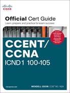
The next several pages walk you through an example that discusses each routing step, in order, through multiple devices. That example uses a case in which host A (172.16.1.9) sends a packet to host B (172.16.2.9), with host routing logic and the five steps showing how R1 forwards the packet.
Figure 18-3 shows a typical IP addressing diagram for an IPv4 network with typical address abbreviations. The diagram can get a little too messy if it lists the full IP address for every router interface. When possible, these diagrams usually list the subnet, and then the last octet or two of the individual IP addresses—just enough so that you know the IP address, but with less clutter. For example, host A uses IP address 172.16.1.9, taking from subnet 172.16.1.0/24 (in which all addresses begin 172.16.1), and the .9 beside the host A icon. As another example, R1 uses address 172.16.1.1 on its LAN interface, 172.16.4.1 on one serial interface, and 172.16.5.1 on the other serial interface.

Now on to the example, with host A (172.16.1.9) sending a packet to host B (172.16.2.9).
Host Forwards the IP Packet to the Default Router (Gateway)
In this example, host A uses some application that sends data to host B (172.16.2.9). After host A has the IP packet sitting in memory, host A’s logic reduces to the following:
![]() My IP address/mask is 172.16.1.9/24, so my local subnet contains numbers 172.16.1.0–172.16.1.255 (including the subnet ID and subnet broadcast address).
My IP address/mask is 172.16.1.9/24, so my local subnet contains numbers 172.16.1.0–172.16.1.255 (including the subnet ID and subnet broadcast address).
![]() The destination address is 172.16.2.9, which is clearly not in my local subnet.
The destination address is 172.16.2.9, which is clearly not in my local subnet.
![]() Send the packet to my default gateway, which is set to 172.16.1.1.
Send the packet to my default gateway, which is set to 172.16.1.1.
![]() To send the packet, encapsulate it in an Ethernet frame. Make the destination MAC address be R1’s G0/0 MAC address (host A’s default gateway).
To send the packet, encapsulate it in an Ethernet frame. Make the destination MAC address be R1’s G0/0 MAC address (host A’s default gateway).
Figure 18-4 pulls these concepts together, showing the destination IP address and destination MAC address in the frame and packet sent by host A in this case. Note that the figure uses a common drawing convention in networking, showing an Ethernet as a few lines, hiding all the detail of the Layer 2 switches.

Routing Step 1: Decide Whether to Process the Incoming Frame
Routers receive many frames in an interface, particularly LAN interfaces. However, a router can and should ignore some of those frames. So, the first step in the routing process begins with a decision of whether a router should process the frame or silently discard (ignore) the frame.
First, the router does a simple but important check (Step 1A in the process summary) so that the router ignores all frames that had bit errors during transmission. The router uses the data-link trailer’s FCS field to check the frame, and if errors occurred in transmission, the router discards the frame. (The router makes no attempt at error recovery; that is, the router does not ask the sender to retransmit the data.)
The router also checks the destination data-link address (Step 1B in the summary) to decide whether the frame is intended for the router. For example, frames sent to the router’s unicast MAC address for that interface are clearly sent to that router. However, a router can actually receive a frame sent to some other unicast MAC address, and routers should ignore these frames.
For example, routers will receive some unicast frames sent to other devices in the VLAN just because of how LAN switches work. Think back to how LAN switches forward unknown unicast frames: frames for which the switch does not list the destination MAC address in the MAC address table. The LAN switch floods those frames. The result? Routers sometimes receive frames destined for some other device, with some other device’s MAC address listed as the destination MAC address. Routers should ignore those frames.
In this example, host A sends a frame destined for R1’s MAC address. So, after the frame is received, and after R1 confirms with the FCS that no errors occurred, R1 confirms that the frame is destined for R1’s MAC address (0200.0101.0101 in this case). All checks have been passed, so R1 will process the frame, as shown in Figure 18-5. (Note that the large rectangle in the figure represents the internals of Router R1.)

Routing Step 2: De-encapsulation of the IP Packet
After the router knows that it ought to process the received frame (per Step 1), the next step is a relatively simple step: de-encapsulating the packet. In router memory, the router no longer needs the original frame’s data-link header and trailer, so the router removes and discards them, leaving the IP packet, as shown in Figure 18-6. Note that the destination IP address remains unchanged (172.16.2.9).

Routing Step 3: Choosing Where to Forward the Packet
While routing Step 2 required little thought, Step 3 requires the most thought of all the steps. At this point, the router needs to make a choice about where to forward the packet next. That process uses the router’s IP routing table, with some matching logic to compare the packet’s destination address with the table.
First, an IP routing table lists multiple routes. Each individual route contains several facts, which in turn can be grouped as shown in Figure 18-7. Part of each route is used to match the destination address of the packet, while the rest of the route lists forwarding instructions: where to send the packet next.

Focus on the entire routing table for a moment, and notice the fact that it lists five routes. Earlier, Figure 18-3 showed the entire example network, with five subnets, so R1 has a route for each of the five subnets.
Next, look at the part of the five routes that Router R1 will use to match packets. To fully define each subnet, each route lists both the subnet ID and the subnet mask. When matching the IP packet’s destination with the routing table, the router looks at the packet’s destination IP address (172.16.2.9) and compares it to the range of addresses defined by each subnet. Specifically, the router looks at the subnet and mask information, which with a little math, the router can figure out in which of those subnets 172.16.2.9 resides (the route for subnet 172.16.2.0/24).
Finally, look to the right side of the figure, to the forwarding instructions for these five routes. After the router matches a specific route, the router uses the forwarding information in the route to tell the router where to send the packet next. In this case, the router matched the route for subnet 172.16.2.0/24, so R1 will forward the packet out its own interface S0/0/0, to Router R2 next, listed with its next-hop router IP address of 172.16.4.2.
Note
Routes for remote subnets typically list both an outgoing interface and next-hop router IP address. Routes for subnets that connect directly to the router list only the outgoing interface, because packets to these destinations do not need to be sent to another router.
Routing Step 4: Encapsulating the Packet in a New Frame
At this point, the router knows how it will forward the packet. However, routers cannot forward a packet without first wrapping a data-link header and trailer around it (encapsulation).
Encapsulating packets for serial links does not require a lot of thought, because of the simplicity of the HDLC and PPP protocols. As discussed back in Chapter 3, “Fundamentals of WANs,” because serial links have only two devices on the link—the sender and the then-obvious receiver; the data-link addressing does not matter. In this example, R1 forwards the packet out S0/0/0, after encapsulating the packet inside an HDLC frame, as shown in Figure 18-8.

Note that with some other types of data links, the router has a little more work to do at this routing step. For example, sometimes a router forwards packets out an Ethernet interface. To encapsulate the IP packet, the router would need to build an Ethernet header, and that Ethernet header’s destination MAC address would need to list the correct value.
For example, consider this different sample network, with an Ethernet WAN link between Routers R1 and R2. R1 matches a route that tells R1 to forward the packet out R1’s G0/1 Ethernet interface to 172.16.6.2 (R2) next. R1 needs to put R2’s MAC address in the header, and to do that, R1 uses its IP ARP table information, as shown in Figure 18-9. If R1 did not have an ARP table entry for 172.16.6.2, R1 would first have to use ARP to learn the matching MAC address.

Routing Step 5: Transmitting the Frame
After the frame has been prepared, the router simply needs to transmit the frame. The router might have to wait, particularly if other frames are already waiting their turn to exit the interface.
Configuring IP Addresses and Connected Routes
Cisco routers enable IPv4 routing globally, by default. Then, to make the router be ready to route packets on a particular interface, the interface must be configured with an IP address and the interface must be configured such that it comes up, reaching a “line status up, line protocol up” state. Only at that point can routers route IP packets in and out a particular interface.
After a router can route IP packets out one or more interfaces, the router needs some routes. Routers can add routes to their routing tables through three methods:
Connected routes: Added because of the configuration of the ip address interface subcommand on the local router
Static routes: Added because of the configuration of the ip route global command on the local router
Routing protocols: Added as a function by configuration on all routers, resulting in a process by which routers dynamically tell each other about the network so that they all learn routes
This second of three sections discusses several variations on how to configure connected routes, while the last major section discusses static routes.
Connected Routes and the ip address Command
A Cisco router automatically adds a route to its routing table for the subnet connected to each interface, assuming that the following two facts are true:
![]() The interface is in a working state. In other words, the interface status in the show interfaces command lists a line status of up and a protocol status of up.
The interface is in a working state. In other words, the interface status in the show interfaces command lists a line status of up and a protocol status of up.
![]() The interface has an IP address assigned through the ip address interface subcommand.
The interface has an IP address assigned through the ip address interface subcommand.
The concept of connected routes is relatively basic. The router of course needs to know the subnet number connected to each of its interfaces, so the router can route packets to that subnet. The router does the math, taking the interface IP address and mask, and calculating the subnet ID. However, the router only needs that route when the interface is up and working, so the router includes a connected route in the routing table only when the interface is working.
Example 18-1 shows the connected routes on Router R1 in Figure 18-10. The first part of the example shows the configuration of IP addresses on all three of R1’s interfaces. The end of the examples lists the output from the show ip route command, which lists these routes with a c as the route code, meaning connected.
Example 18-1 Connected and Local Routes on Router R1
! Excerpt from show running-config follows...
!
interface GigabitEthernet0/0
ip address 172.16.1.1 255.255.255.0
!
interface Serial0/0/0
ip address 172.16.4.1 255.255.255.0
!
interface Serial0/0/1
ip address 172.16.5.1 255.255.255.0
R1# show ip route
Codes: L - local, C - connected, S - static, R - RIP, M - mobile, B - BGP
D - EIGRP, EX - EIGRP external, O - OSPF, IA - OSPF inter area
N1 - OSPF NSSA external type 1, N2 - OSPF NSSA external type 2
E1 - OSPF external type 1, E2 - OSPF external type 2
i - IS-IS, su - IS-IS summary, L1 - IS-IS level-1, L2 - IS-IS level-2
ia - IS-IS inter area, * - candidate default, U - per-user static route
o - ODR, P - periodic downloaded static route, H - NHRP, l - LISP
+ - replicated route, % - next hop override
Gateway of last resort is not set
172.16.0.0/16 is variably subnetted, 6 subnets, 2 masks
C 172.16.1.0/24 is directly connected, GigabitEthernet0/0
L 172.16.1.1/32 is directly connected, GigabitEthernet0/0
C 172.16.4.0/24 is directly connected, Serial0/0/0
L 172.16.4.1/32 is directly connected, Serial0/0/0
C 172.16.5.0/24 is directly connected, Serial0/0/1
L 172.16.5.1/32 is directly connected, Serial0/0/1
Take a moment to look closely at each of the three highlighted routes in the output of show ip route. Each lists a C in the first column, and each has text that says “directly connected”; both identify the route as connected to the router. The early part of each route lists the matching parameters (subnet ID and mask), as shown in the earlier example in Figure 18-7. The end of each of these routes lists the outgoing interface.
Note that the router also automatically produces a different kind of route, called a local route. The local routes define a route for the one specific IP address configured on the router interface. Each local route has a /32 prefix length, defining a host route, which defines a route just for that one IP address. For example, the last local route, for 172.16.5.1/32, defines a route that matches only the IP address of 172.16.5.1. Routers use these local routes that list their own local IP addresses to more efficiently forward packets sent to the router itself.
The ARP Table on a Cisco Router
After a router has added these connected routes, the router can route IPv4 packets between those subnets. To do so, the router makes use of its IP ARP table.
The IPv4 ARP table lists the IPv4 address and matching MAC address of hosts connected to the same subnet as the router. When forwarding a packet to a host on the same subnet, the router encapsulates the packet, with a destination MAC address as found in the ARP table. If the router wants to forward a packet to an IP address on the same subnet as the router, but does not find an ARP table entry for that IP address, the router will use ARP messages to learn that device’s MAC address.
Example 18-2 shows R1’s ARP table based on the previous example. The output lists R1’s own IP address of 172.16.1.1, with an age of -, meaning that this entry does not time out. Dynamically learned ARP table entries have an upward counter, like the 35-minute value for the ARP table entry for IP address 172.16.1.9. By default, IOS will timeout (remove) an ARP table entry after 240 minutes in which the entry is not used. (IOS resets the timer to 0 when an ARP table entry is used.) Note that to experiment in lab, you might want to empty all dynamic entries (or a single entry for one IP address) using the clear ip arp [ip-address] EXEC command.
Example 18-2 Displaying a Router’s IP ARP Table
R2# show ip arp
Protocol Address Age (min) Hardware Addr Type Interface
Internet 172.16.1.1 - 0200.2222.2222 ARPA GigabitEthernet0/0
Internet 172.16.1.9 35 0200.3333.3333 ARPA GigabitEthernet0/0
Thinking about how Router R1 forwards a packet to host A (172.16.1.9), over that final subnet, R1 does the following:
1. R1 looks in its ARP table for an entry for 172.16.1.9.
2. R1 encapsulates the IP packet in an Ethernet frame, adding destination 0200.3333.3333 to the Ethernet header (as taken from the ARP table).
3. R1 transmits the frame out interface G0/0.
Routing Between Subnets on VLANs
Almost all enterprise networks use VLANs. To route IP packets in and out of those VLANs—or more accurately, the subnets that sit on each of those VLANs—some router needs to have an IP address in each subnet and have a connected route to each of those subnets. Then the hosts in each subnet can use the router IP addresses as their default gateways, respectively.
Three options exist for connecting a router to each subnet on a VLAN. However, the first option requires too many interfaces and links, and is only mentioned to make the list complete:
![]() Use a router, with one router LAN interface and cable connected to the switch for each and every VLAN (typically not used).
Use a router, with one router LAN interface and cable connected to the switch for each and every VLAN (typically not used).
![]() Use a router, with a VLAN trunk connecting to a LAN switch.
Use a router, with a VLAN trunk connecting to a LAN switch.
![]() Use a Layer 3 switch.
Use a Layer 3 switch.
Figure 18-11 shows an example network where the second and third options both happen to be used. The figure shows a central site campus LAN on the left, with 12 VLANs. At the central site, two of the switches act as Layer 3 switches, combining the functions of a router and a switch, routing between all 12 subnets/VLANs. The remote branch sites on the right side of the figure each use two VLANs; each router uses a VLAN trunk to connect to and route for both VLANs.

Note that Figure 18-11 just shows an example. The engineer could use Layer 3 switching at each site, or routers with VLAN trunking at each site. This chapter focuses more on the details of how to configure the features, as discussed in the next few pages.
Configuring Routing to VLANs Using 802.1Q on Routers
This next topic discusses how to route packets to subnets associated with VLANs connected to a router 802.1Q trunk. That long description can be a bit of a chore to repeat each time someone wants to discuss this feature, so over time, the networking world has instead settled on a shorter and more interesting name for this feature: router-on-a-stick (ROAS).
ROAS uses router VLAN trunking configuration to give the router a logical router interface connected to each VLAN, and therefore each subnet that sits on a separate VLAN. That trunking configuration revolves around subinterfaces. The router needs to have an IP address/mask associated with each VLAN on the trunk. However, the router uses only one physical interface on which to configure the ip address command. Cisco solves this problem by creating multiple virtual router interfaces, one associated with each VLAN on that trunk (at least for each VLAN that you want the trunk to support). Cisco calls these virtual interfaces subinterfaces.
The ROAS configuration creates a subinterface for each VLAN on the trunk, and the router then treats all frames tagged with that associated VLAN ID as if they came in or out of that subinterface. Figure 18-12 shows the concept with Router B1, one of the branch routers from Figure 18-11. Because this router needs to route between only two VLANs, the figure also shows two subinterfaces, named G0/0.10 and G0/0.20, which create a new place in the configuration where the per-VLAN configuration settings can be made. The router treats frames tagged with VLAN 10 as if they came in or out of G0/0.10, and frames tagged with VLAN 20 as if they came in or out G0/0.20.

In addition, most Cisco routers do not attempt to negotiate trunking, so in most cases, both the router and switch need to manually configure trunking. This chapter discusses the router side of that trunking configuration; the matching switch interface would need to be configured with the switchport mode trunk command.
Example 18-3 shows a full example of the 802.1Q trunking configuration required on Router B1 in the figure. More generally, these steps detail how to configure 802.1Q trunking on a router:
Step 1. Use the interface type number.subint command in global configuration mode to create a unique subinterface for each VLAN that needs to be routed.
Step 2. Use the encapsulation dot1q vlan_id command in subinterface configuration mode to enable 802.1Q and associate one specific VLAN with the subinterface.
Step 3. Use the ip address address mask command in subinterface configuration mode to configure IP settings (address and mask).
Example 18-3 Router Configuration for the 802.1Q Encapsulation Shown in Figure 18-12
B1# show running-config
! Only pertinent lines shown
interface gigabitethernet 0/0
! No IP address up here! No encapsulation up here!
!
interface gigabitethernet 0/0.10
encapsulation dot1q 10
ip address 10.1.10.1 255.255.255.0
!
interface gigabitethernet 0/0.20
encapsulation dot1q 20
ip address 10.1.20.1 255.255.255.0
!
B1# show ip route
Codes: L - local, C - connected, S - static, R - RIP, M - mobile, B - BGP
! Lines omitted for brevity
10.0.0.0/8 is variably subnetted, 4 subnets, 2 masks
C 10.1.10.0/24 is directly connected, GigabitEthernet0/0.10
L 10.1.10.1/32 is directly connected, GigabitEthernet0/0.10
C 10.1.20.0/24 is directly connected, GigabitEthernet0/0.20
L 10.1.20.1/32 is directly connected, GigabitEthernet0/0.20
First, look at the subinterface numbers. The subinterface number begins with the period, like .10 and .20 in this case. These numbers can be any number from 1 up through a very large number (over 4 billion). The number just needs to be unique among all subinterfaces associated with this one physical interface. In fact, the subinterface number does not even have to match the associated VLAN ID. (The encapsulation command, and not the subinterface number, defines the VLAN ID associated with the subinterface.)
Note
Although not required, most sites do choose to make the subinterface number match the VLAN ID, as shown in Example 18-3, just to avoid confusion.
Each subinterface configuration lists two subcommands. One command (encapsulation) enables trunking and defines the VLAN whose frames are considered to be coming in and out of the subinterface. The ip address command works the same way it does on any other interface. Note that if the physical Ethernet interface reaches an up/up state, the subinterface should as well, which would then let the router add the connected routes shown at the bottom of the example.
Now that the router has a working interface, with IPv4 addresses configured, the router can route IPv4 packets on these subinterfaces. That is, the router treats these subinterfaces like any physical interface in terms of adding connected routes, matching those routes and forwarding packets to/from those connected subnets.
Note
As a brief aside, while Example 18-3 shows 802.1Q configuration, the Inter-Switch Link (ISL) configuration on the same router would be practically identical. Just substitute the keyword isl instead of dot1q in each case.
Example 18-3 shows one way to configure ROAS on a router, but that particular example avoids using the native VLAN. However, each 802.1Q trunk has one native VLAN, and when used, the configuration to use that native VLAN differs, with two options for the router side of the configuration:
![]() Configure the ip address command on the physical interface, but without an encapsulation command; the router considers this physical interface to be using the native VLAN.
Configure the ip address command on the physical interface, but without an encapsulation command; the router considers this physical interface to be using the native VLAN.
![]() Configure the ip address command on a subinterface, and use the encapsulation...native subcommand.
Configure the ip address command on a subinterface, and use the encapsulation...native subcommand.
Example 18-4 shows both configuration options with a small change to the same configuration in Example 18-3. In this case, VLAN 10 becomes the native VLAN. The top part of the example shows the option to configure the router to use native VLAN 10, assuming that the switch also has been configured to use native VLAN 10 as well. The second half of the example shows how to configure that same native VLAN on a subinterface.
Example 18-4 Router Configuration Using Native VLAN 10 on Router B1
! First option: put the native VLAN IP address on the physical interface
interface gigabitethernet 0/0
ip address 10.1.10.1 255.255.255.0
!
interface gigabitethernet 0/0.20
encapsulation dot1q 20
ip address 10.1.20.1 255.255.255.0
! Second option: like normal, but add the native keyword
interface gigabitethernet 0/0.10
encapsulation dot1q 10 native
ip address 10.1.10.1 255.255.255.0
!
interface gigabitethernet 0/0.20
encapsulation dot1q 20
ip address 10.1.20.1 255.255.255.0
Besides just scanning the configuration, the show vlans command on a router spells out which router trunk interfaces use which VLANs, which VLAN is the native VLAN, plus some packet statistics. Example 18-5 shows a sample, based on the Router B1 configuration in Example 18-4 (bottom half), in which native VLAN 10 is configured on subinterface G0/0.10. Note that the output identifies VLAN 1 associated with the physical interface, VLAN 10 as the native VLAN associated with G0/0.10, and VLAN 20 associated with G0/0.20.
Example 18-5 Sample show vlans Command to Match Sample Router Trunking Configuration
R1# show vlans
Virtual LAN ID: 1 (IEEE 802.1Q Encapsulation)
vLAN Trunk Interface: GigabitEthernet0/0
Protocols Configured: Address: Received: Transmitted:
Other 0 83
69 packets, 20914 bytes input
147 packets, 11841 bytes output
Virtual LAN ID: 10 (IEEE 802.1Q Encapsulation)
vLAN Trunk Interface: GigabitEthernet0/0.10
This is configured as native Vlan for the following interface(s) :
GigabitEthernet0/0
Protocols Configured: Address: Received: Transmitted:
IP 10.1.10.1 2 3
Other 0 1
3 packets, 722 bytes input
4 packets, 264 bytes output
Virtual LAN ID: 20 (IEEE 802.1Q Encapsulation)
vLAN Trunk Interface: GigabitEthernet0/0.20
Protocols Configured: Address: Received: Transmitted:
IP 10.1.20.1 0 134
Other 0 1
0 packets, 0 bytes input
135 packets, 10498 bytes output
Configuring Routing to VLANs Using a Layer 3 Switch
The other option for routing traffic to VLANs uses a device called a Layer 3 switch or multilayer switch. As introduced back in Chapter 11, “Implementing Ethernet Virtual LANs,” a Layer 3 switch is one device that does two primary functions: Layer 2 LAN switching and Layer 3 IP routing. The Layer 2 switch function forwards frames inside each VLAN, but it will not forward frames between VLANs. The Layer 3 forwarding logic—routing—forwards IP packets between VLANs.
The configuration of a Layer 3 switch mostly looks like the Layer 2 switching configuration shown back in Part II of this book, with a small bit of configuration added for the Layer 3 functions. The Layer 3 switching function needs a virtual interface connected to each VLAN internal to the switch. These VLAN interfaces act like router interfaces, with an IP address and mask. The Layer 3 switch has an IP routing table, with connected routes off each of these VLAN interfaces. (These interfaces are also referred to as switched virtual interfaces [SVI].)
To show the concept, Figure 18-13 shows the design changes and configuration concept for the same branch office used in Figures 18-11 and 18-12. The figure shows the Layer 3 switch function with a router icon inside the switch, to emphasize that the switch routes the packets. The branch still has two user VLANs, so the Layer 3 switch needs one VLAN interface for each VLAN. In addition, the traffic still needs to get to the router to access the WAN, so the switch uses a third VLAN (VLAN 30 in this case) for the link to Router B1. This link would not be a trunk, but would be an access link.

The following steps show how to configure Layer 3 switching. Note that on some switches, like the 2960 switches used for the examples in this book, the ability to route IPv4 packets must be enabled first, with a reload of the switch required to enable the feature. The rest of the steps after Step 1 would apply to all models of Cisco switches that are capable of doing Layer 3 switching.
Step 1. On some older models of switches, enable hardware support for IPv4 routing. For example, on 2960 switches, use the sdm prefer lanbase-routing in global configuration mode and reload the switch.
Step 2. Use the ip routing command in global configuration mode to enable IPv4 routing on the switch.
Step 3. Use the interface vlan vlan_id command in global configuration mode to create VLAN interfaces for each VLAN for which the Layer 3 switch is routing packets.
Step 4. Use the ip address address mask command in interface configuration mode to configure an IP address and mask on the VLAN interface, enabling IPv4 on that VLAN interface.
Step 5. Use the no shutdown command in interface configuration mode to enable the VLAN interface (if it is currently in a shutdown state).
Example 18-6 shows the configuration to match Figure 18-13. In this case, switch SW1, a 2960, has already used the sdm prefer lanbase-routing global command and been reloaded. The example shows the related configuration on all three VLAN interfaces.
Example 18-6 VLAN Interface Configuration for Layer 3 Switching
ip routing
!
interface vlan 10
ip address 10.1.10.1 255.255.255.0
!
interface vlan 20
ip address 10.1.20.1 255.255.255.0
!
interface vlan 30
ip address 10.1.30.1 255.255.255.0
With the VLAN configuration shown here, the switch is ready to route packets between the VLANs as shown in Figure 18-13. To support the routing of packets, the switch adds connected IP routes, as shown in Example 18-7; note that each route is listed as being connected to a different VLAN interface.
Example 18-7 Connected Routes on a Layer 3 Switch
SW1# show ip route
! legend omitted for brevity
10.0.0.0/8 is variably subnetted, 6 subnets, 2 masks
C 10.1.10.0/24 is directly connected, Vlan10
L 10.1.10.1/32 is directly connected, Vlan10
C 10.1.20.0/24 is directly connected, Vlan20
L 10.1.20.1/32 is directly connected, Vlan20
C 10.1.30.0/24 is directly connected, Vlan30
L 10.1.30.1/32 is directly connected, Vlan30
The switch would also need additional routes to the rest of the network shown in Figure 18-11, possibly using static routes as discussed in the final major section of this chapter.
Configuring Static Routes
All routers add connected routes, as discussed in the previous section. Then, most networks use dynamic routing protocols to cause each router to learn the rest of the routes in an internetwork. Networks use static routes—routes added to a routing table through direct configuration—much less often than dynamic routing. However, static routes can be useful at times, and they happen to be useful learning tools as well. This last of three major sections in the chapter discusses static routes.
Static Route Configuration
IOS allows the definition of individual static routes using the ip route global configuration command. Every ip route command defines a destination that can be matched, usually with a subnet ID and mask. The command also lists the forwarding instructions, typically listing either the outgoing interface or the next-hop router’s IP address. IOS then takes that information and adds that route to the IP routing table.
As an example, Figure 18-14 shows a small IP network. The diagram actually holds a subset of Figure 18-3, from earlier in this chapter, with some of the unrelated details removed. The figure shows only the details related to a static route on R1, for subnet 172.16.2.0/24, which sits on the far right. To create that static route on R1, R1 will configure the subnet ID and mask, and either R1’s outgoing interface (S0/0/0), or R2 as the next-hop router IP address (172.16.4.2).

Example 18-8 shows the configuration of a couple of sample static routes. In particular, it shows routes on Router R1 in Figure 18-15, for the two subnets on the right side of the figure.

Example 18-8 Static Routes Added to R1
ip route 172.16.2.0 255.255.255.0 172.16.4.2
ip route 172.16.3.0 255.255.255.0 S0/0/1
The two example ip route commands show the two different styles. The first command shows subnet 172.16.2.0, mask 255.255.255.0, which sits on a LAN near Router R2. That same first command lists 172.16.4.2, R2’s IP address, as the next-hop router. This route basically says this: To send packets to the subnet off Router R2, send them to R2.
The second route has the same kind of logic, but instead of identifying the next router by IP address, it lists the local router’s outgoing interface. This route basically states: To send packets to the subnet off Router R3, send them out my own local S0/0/1 interface (which happens to connect to R3).
The routes created by these two ip route commands actually look a little different in the IP routing table. Both are static routes. However, the route that used the outgoing interface configuration is also noted as a connected route; this is just a quirk of the output of the show ip route command.
Example 18-9 lists these two routes using the show ip route static command. This command lists the details of static routes only, but it also lists a few statistics about all IPv4 routes. For example, the example shows two lines, for the two static routes configured in Example 18-8, but statistics state that this router has routes for ten subnets.
Example 18-9 Static Routes Added to R1
R1# show ip route static
Codes: L - local, C - connected, S - static, R - RIP, M - mobile, B - BGP
! lines omitted for brevity
Gateway of last resort is not set
172.16.0.0/16 is variably subnetted, 10 subnets, 2 masks
S 172.16.2.0/24 [1/0] via 172.16.4.2
S 172.16.3.0/24 is directly connected, Serial0/0/1
IOS adds and removes these static routes dynamically over time, based on whether the outgoing interface is working or not. For example, in this case, if R1’s S0/0/1 interface fails, R1 removes the static route to 172.16.3.0/24 from the IPv4 routing table. Later, when the interface comes up again, IOS adds the route back to the routing table.
Note that most sites use dynamic routing protocols to learn all the routes to remote subnets. However, when not using a dynamic routing protocol, the routers would need to configure static routes. For example, if the routers had only the configuration shown in the examples so far, PC A (from Figure 18-15) would not be able to receive packets back from PC B, because Router R2 does not have a route for PC A’s subnet. R2 would need static routes for other subnets, as would R3.
Note
The static routes shown so far in this chapter are called network routes or subnet routes because the command defines a route to an IP network or subnet, in comparison to a host route or default route, as explained in the next few pages.
Static Host Routes
Earlier, this chapter defined a host route as a route for a single host address, as noted with the IP address and a /32 mask. The earlier examples focused on the local routes added as a result of the ip address command; those routes are all host routes, with a /32 mask.
The ip route command can create static routes for remote hosts by using a mask of 255.255.255.255. This might make sense for cases in which redundant paths exist, and you want traffic to most of the hosts in the subnet to flow over one path, and traffic for one specific host to flow over the other path. For instance, you could define these two static routes for subnet 10.1.1.0/24 and host 10.1.1.9, with two different next-hop addresses, as follows:
ip route 10.1.1.0 255.255.255.0 10.2.2.2
ip route 10.1.1.9 255.255.255.255 10.9.9.9
Note that these two routes overlap: a packet sent to 10.1.1.9 that arrives at the router would match both routes. When that happens, routers use the most specific route (that is, the route with the longest prefix length). So, a packet sent to 10.1.1.9 would be forwarded to next-hop router 10.9.9.9, and packets sent to other destinations in subnet 10.1.1.0/24 would be sent to next-hop router 10.2.2.2.
Note that the section “IP Forwarding by Matching the Most Specific Route” in Chapter 24, “Troubleshooting IPv4 Routing,” gets into this topic in more detail.
Static Routes with No Competing Routes
If the configured route has no competing routes, the router still checks a few rules before adding the route to its IP routing table. The router first checks for any competing routes (that is, whether there are any other routes for the exact same subnet). The other routes could be learned by a routing protocol, or be another static route.
Even if no competing routes exist, IOS also considers the following before adding the route to its routing table:
![]() For ip route commands that list an outgoing interface, that interface must be in an up/up state.
For ip route commands that list an outgoing interface, that interface must be in an up/up state.
![]() For ip route commands that list a next-hop IP address, the local router must have a route to reach that next-hop address.
For ip route commands that list a next-hop IP address, the local router must have a route to reach that next-hop address.
For example, earlier in Example 18-8, R1’s command ip route 172.16.2.0 255.255.255.0 172.16.4.2 defines a static route. Assume there were no competing routes and all links were working. Based on this route, R1 looks at its IP routing table and finds a route matching next-hop address 172.16.4.2 (R1’s connected route for subnet 172.16.4.0/24). As a result, R1 adds the static route to subnet 172.16.2.0/24. Later, if R1’s S0/0/0 were to fail, R1 would remove its connected route to 172.16.4.0/24, which would then cause R1 to remove its static route to 172.16.2.0/24.
You can also configure a static route so that IOS ignores these basic checks, always putting the IP route in the routing table. To do so, just use the permanent keyword on the ip route command. For example, by adding the permanent keyword to the end of the two commands in Example 18-8 as demonstrated in Example 18-10, R1 would now add these routes, regardless of whether the two WAN links were up.
Example 18-10 Permanently Adding Static Routes to the IP Routing Table (Router R1)
ip route 172.16.2.0 255.255.255.0 172.16.4.2 permanent
ip route 172.16.3.0 255.255.255.0 S0/0/1 permanent
Note that although the permanent keyword lets the router keep the route in the routing table without checking the outgoing interface or route to the next-hop address, it does not magically fix a broken route. For example, if the outgoing interface fails, the route will remain in the routing table, but the router cannot forward packets because the outgoing interface is down.
Static Routes with Competing Routes
Next, consider the case in which a static route competes with other static routes or routes learned by a routing protocol. That is, the ip route command defines a route to a subnet, but the router also knows of other static or dynamically learned routes to reach that same subnet. In these cases, the router must first decide which routing source has the better administrative distance, with lower being better, and then use the route learned from the better source.
To see how that works, consider the example illustrated in Figure 18-16, which shows a branch office with two WAN links: one very fast Gigabit Ethernet link and one rather slow (but cheap) T1. In this design, the network uses Open Shortest Path First Version 2 (OSPFv2) over the primary link, learning a route for subnet 172.16.2.0/24. R1 also defines a static route over the backup link to that exact same subnet, so R1 must choose whether to use the static route or the OSPF-learned route.

IOS considers static routes better than OSPF-learned routes. By default, IOS gives static routes an administrative distance of 1 and OSPF routes an administrative distance of 110. Using these defaults in Figure 18-16, R1 would use the lower path to reach subnet 172.16.2.0/24 in this case, which is not the intended design. Instead, the engineer prefers to use the OSPF-learned routes over the much-faster primary link, and use the static route over the backup link only as needed when the primary link fails.
To instead prefer the OSPF routes, the configuration would need to change the administrative distance settings and use what many networkers call a floating static route. A floating static route floats or moves into and out of the IP routing table depending on whether the better (lower) administrative distance route learned by the routing protocol happens to exist currently. Basically, the router ignores the static route during times when the better routing protocol route is known.
To implement a floating static route, just override the default administrative distance on the static route, making the value larger than the default administrative distance of the routing protocol. For example, the ip route 172.16.2.0 255.255.255.0 172.16.5.3 130 command on R1 would do exactly that, setting the static route’s administrative distance to 130. As long as the primary link stays up, and OSPF on R1 learns a route for 172.16.2.0/24, with administrative distance of 110, R1 ignores the static route.
Finally, note that while the show ip route command lists the administrative distance of most routes, as the first of two numbers inside two brackets, the show ip route subnet command plainly lists the administrative distance. Example 18-11 shows a sample, matching this most recent example.
Example 18-11 Displaying the Administrative Distance of the Static Route
R1# show ip route static
! Legend omitted for brevity
172.16.0.0/16 is variably subnetted, 6 subnets, 2 masks
S 172.16.2.0/24 is directly connected, Serial0/0/1
R1# show ip route 172.16.2.0
Routing entry for 172.16.2.0/24
Known via "static", distance 130, metric 0 (connected)
Routing Descriptor Blocks:
* directly connected, via Serial0/0/1
Route metric is 0, traffic share count is 1
Static Default Routes
When a router tries to route a packet, the router might not match the packet’s destination IP address with any route. When that happens, the router normally just discards the packet.
Routers can be configured so that they use either a statically configured or dynamically learned default route. The default route matches all packets, so that if a packet does not match any other more specific route in the routing table, the router can at least forward the packet based on the default route.
One classic example in which companies might use static default routes in their enterprise TCP/IP networks is when the company has many remote sites, each with a single, relatively slow WAN connection. Each remote site has only one possible physical route to use to send packets to the rest of the network. So, rather than use a routing protocol, which sends messages over the WAN and uses precious WAN bandwidth, each remote router might use a default route that sends all traffic to the central site, as shown in Figure 18-17.

IOS allows the configuration of a static default route by using special values for the subnet and mask fields in the ip route command: 0.0.0.0 and 0.0.0.0. For example, the command ip route 0.0.0.0 0.0.0.0 S0/0/1 creates a static default route on Router B1—a route that matches all IP packets—and sends those packets out interface S0/0/1.
Example 18-12 shows an example of a static default route, using Router R2 from Figure 18-16. Earlier, that figure, along with Example 18-10, showed R1 with static routes to the two subnets on the right side of the figure. Example 18-12 shows R2, on the right, using a static default route to route packets back to the left side of the figure.
Example 18-12 Adding a Static Default Route on R2 (Figure 18-16)
R2# configure terminal
Enter configuration commands, one per line. End with CNTL/Z.
R2(config)# ip route 0.0.0.0 0.0.0.0 s0/0/1
R2(config)# ^Z
R2# show ip route
Codes: L - local, C - connected, S - static, R - RIP, M - mobile, B - BGP
D - EIGRP, EX - EIGRP external, O - OSPF, IA - OSPF inter area
N1 - OSPF NSSA external type 1, N2 - OSPF NSSA external type 2
E1 - OSPF external type 1, E2 - OSPF external type 2
i - IS-IS, su - IS-IS summary, L1 - IS-IS level-1, L2 - IS-IS level-2
ia - IS-IS inter area, * - candidate default, U - per-user static route
o - ODR, P - periodic downloaded static route, H - NHRP, l - LISP
+ - replicated route, % - next hop override
Gateway of last resort is 0.0.0.0 to network 0.0.0.0
S* 0.0.0.0/0 is directly connected, Serial0/0/1
172.16.0.0/16 is variably subnetted, 4 subnets, 2 masks
C 172.16.2.0/24 is directly connected, GigabitEthernet0/0
L 172.16.2.2/32 is directly connected, GigabitEthernet0/0
C 172.16.4.0/24 is directly connected, Serial0/0/1
L 172.16.4.2/32 is directly connected, Serial0/0/1
The output of the show ip route command lists a few new and interesting facts. First, it lists the route with a code of S, meaning static, but also with a *, meaning it is a candidate default route. A router can learn about more than one default route, and the router then has to choose which one to use; the * means that it is at least a candidate to become the default route. Just above, the “Gateway of Last Resort” refers to the chosen default route, which in this case is the just-configured static route with outgoing interface S0/0/1.
Troubleshooting Static Routes
This entire section about static routes includes scattered comments that can help you troubleshoot static routes; however, the exam topics for this version of the exam happens to specifically mention troubleshooting for static routes. To that end, this final topic of the chapter summarizes the key points related to troubleshooting static routes, some already mentioned in this chapter, and some added here in this section.
This topic breaks static route troubleshooting into three perspectives: the route is in the routing table but is incorrect; the route is not in the routing table; the route is in the routing table, and is correct, but the packets do not arrive.
Troubleshooting Incorrect Static Routes that Appear in the IP Routing Table
This first troubleshooting item can be obvious, but it is worth pausing to think about. A static route is only as good as the input typed into the ip route command. IOS checks the syntax, and as mentioned earlier, makes a few other checks that this section reviews in the next heading. But once those checks are passed, IOS puts the route into the IP routing table, even if the route had poorly chosen parameters.
For instance, an exam question might show addresses 192.168.1.101 and .102, with mask /26, and you see a router with a command ip route 192.168.1.64 255.255.255.224 192.168.1.65. Did you see the problem immediately? The range of addresses in subnet 192.168.1.64, with mask 255.255.255.224, does not include the .101 and .102 addresses. So the ip route command has good syntax, but the engineer made a subnetting math mistake.
When you see an exam question that has static routes, and you see them in the output of show ip route, remember to check on these items:
![]() Is there a subnetting math error in the subnet ID and mask?
Is there a subnetting math error in the subnet ID and mask?
![]() Is the next-hop IP address correct, and referencing an IP address on a neighboring router?
Is the next-hop IP address correct, and referencing an IP address on a neighboring router?
![]() Is the outgoing interface correct, and referencing an interface on the local route (that is, the same router where the static route is configured)?
Is the outgoing interface correct, and referencing an interface on the local route (that is, the same router where the static route is configured)?
The Static Route Does Not Appear in the IP Routing Table
An ip route command can have correct syntax, accepted and added to the running-config file, and saved into the startup-config file, but never be placed into the IP routing table and seen in the output of the show ip route command. Why? Well, the earlier topics under headings “Static Routes with No Competing Routes” and “Static Routes with Competing Routes” explained the reasons.
For easier review and study, here are the reasons why an ip route command would be accepted when typed in the CLI, but the route would not appear in the IP routing table. Note that all three reasons can change over time; that is, the route may not appear right now, then conditions change, and then the route appears.
![]() The outgoing interface listed in the ip route command is not up/up.
The outgoing interface listed in the ip route command is not up/up.
![]() The next-hop router IP address listed in the ip route command is not reachable (that is, there is no route that matches the next-hop address).
The next-hop router IP address listed in the ip route command is not reachable (that is, there is no route that matches the next-hop address).
![]() A better competing route (another route to the exact same subnet ID and mask) exists, and that competing route has a better (lower) administrative distance.
A better competing route (another route to the exact same subnet ID and mask) exists, and that competing route has a better (lower) administrative distance.
The Correct Static Route Appears but Works Poorly
This last section is a place to make two points, one mainstream, and one point to review a bit of trivia.
First, on the mainstream point, the static route can be perfect, but the packets from one host to the next still may not arrive. An incorrect static route is just one of many items to check when you’re troubleshooting problems like “host A cannot connect to server B.” The root cause may be the static route, or it may be something else. Chapters 23 and 24 go into some depth about troubleshooting these types of problems.
On the more trivial point, you may recall the permanent keyword on the ip route command, as discussed earlier in the section titled “Static Routes with No Competing Routes.” Basically, this keyword tells IOS to skip the checks of the current status of the outgoing interface and the check of a route for the next-hop router IP address. Any time you see an exam question with an ip route command with the permanent keyword, you need to do these checks yourself. IOS will put the route in the routing table, and if the interface is down or the next-hop address is unreachable, the router cannot possibly forward packets with that route.
Chapter Review
One key to doing well on the exams is to perform repetitive spaced review sessions. Review this chapter’s material using either the tools in the book, DVD, or interactive tools for the same material found on the book’s companion website. Refer to the “Your Study Plan” element for more details. Table 18-2 outlines the key review elements and where you can find them. To better track your study progress, record when you completed these activities in the second column.


Command References
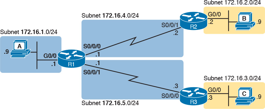
Tables 18-4 and 18-5 list configuration and verification commands used in this chapter. As an easy review exercise, cover the left column in a table, read the right column, and try to recall the command without looking. Then repeat the exercise, covering the right column, and try to recall what the command does.
Table 18-4 Chapter 18 Configuration Command Reference

Table 18-5 Chapter 18 EXEC Command Reference