Chapter 3. Fundamentals of WANs
This chapter covers the following exam topics:
1.0 Network Fundamentals
1.1 Compare and contrast OSI and TCP/IP models
1.6 Select the appropriate cabling type based on implementation requirements
3.0 Routing Technologies
3.1 Describe the routing concepts
3.1.c Frame rewrite
Most Layer 1 and 2 networking technology falls into one of two primary categories: wide-area networks (WAN) and local area networks (LAN). Because both WANs and LANs match OSI Layers 1 and 2, they have many similarities: Both define cabling details, transmission speeds, encoding, and how to send data over physical links, as well as data-link frames and forwarding logic.
Of course, WANs and LANs have many differences as well, most notably the distances between nodes and the business model for paying for the network. First, in terms of the distance, the terms local and wide give us a small hint: LANs typically include nearby devices, whereas WANs connect devices that can be far apart, potentially hundreds or thousands of miles apart.
The other big difference between the two is this: You pay for and own LANs, but you lease WANs. With LANs, you buy the cables and LAN switches and install them in spaces you control. WANs physically pass through other people’s property, and you do not have the right to put your cables and devices there. So, a few companies, like a telephone company or cable company, install and own their own devices and cables, creating their own networks, and lease the right to send data over their networks.
This chapter introduces WANs in three major sections. The first introduces leased line WANs, a type of WAN link that has been part of enterprise networks since the 1960s. The second part shows how Ethernet can be used to create WAN services by taking advantage of the longer cable length possibilities of modern fiber-optic Ethernet standards. The last part of the chapter takes a survey of common WAN technology used to access the Internet.
“Do I Know This Already?” Quiz
Take the quiz (either here, or use the PTP software) if you want to use the score to help you decide how much time to spend on this chapter. The answers are at the bottom of the page following the quiz, and the explanations are in DVD Appendix C and in the PTP software.

1. In the cabling for a leased line, which of the following typically connects to a four-wire line provided by a telco?
a. Router serial interface without internal CSU/DSU
b. CSU/DSU
c. Router serial interface with internal transceiver
d. Switch serial interface
2. Which of the following is an accurate speed at which a leased line can operate in the United States?
a. 100 Mbps
b. 100 Kbps
c. 256 Kbps
d. 6.4 Mbps
3. Which of the following fields in the HDLC header used by Cisco routers does Cisco add, beyond the ISO standard HDLC?
a. Flag
b. Type
c. Address
d. FCS
4. Two routers, R1 and R2, connect using an Ethernet over MPLS service. The service provides point-to-point service between these two routers only, as a Layer 2 Ethernet service. Which of the following are the most likely to be true about this WAN? (Choose two answers.)
a. R1 will connect to a physical Ethernet link, with the other end of the cable connected to R2.
b. R1 will connect to a physical Ethernet link, with the other end of the cable connected to a device at the WAN service provider point of presence.
c. R1 will forward data-link frames to R2 using an HDLC header/trailer.
d. R1 will forward data-link frames to R2 using an Ethernet header/trailer.
5. Which of the following Internet access technologies, used to connect a site to an ISP, offers asymmetric speeds? (Choose two answers.)
a. Leased lines
b. DSL
c. Cable Internet
d. BGP
6. Fred has just added DSL service at his home, with a separate DSL modem and consumer-grade router with four Ethernet ports. Fred wants to use the same old phone he was using before the installation of DSL. Which is most likely true about the phone cabling and phone used with his new DSL installation?
a. He uses the old phone, cabled to one of the router/switch device’s Ethernet ports.
b. He uses the old phone, cabled to the DSL modem’s ports.
c. He uses the old phone, cabled to an existing telephone port and not to any new device.
d. The old phone must be replaced with a digital phone.
Answers to the “Do I Know This Already?” quiz:
1 B 2 C 3 B 4 B and D 5 B and C 6 C
Foundation Topics
Leased-Line WANs
Imagine that you are the primary network engineer for an enterprise TCP/IP internetwork. Your company is building a new building at a site 100 miles away from your corporate headquarters. You will of course install a LAN throughout the new building, but you also need to connect that new remote LAN to the rest of the existing enterprise TCP/IP network.
To connect the new building’s LAN to the rest of the existing corporate network, you need some kind of a WAN. At a minimum, that WAN must be able to send data from the remote LAN back to the rest of the existing network and vice versa. Leased line WANs do exactly that, forwarding data between two routers.
From a basic point of view, a leased line WAN works a lot like an Ethernet crossover cable connecting two routers, but with few distance limitations. Each router can send at any time (full duplex) over the leased line, for tens, hundreds, or even thousands of miles.
This section begins by giving some perspective about where leased lines fit with LANs and routers, because one main goal for a WAN is to move data between LANs. The rest of this first section explains the physical details about leased lines, followed with information about data-link protocols.
Positioning Leased Lines with LANs and Routers
The vast majority of end-user devices in an enterprise or small office/home office (SOHO) network connect directly into a LAN. Many PCs use an Ethernet network interface card (NIC) that connects to a switch. More and more, devices use 802.11 wireless LANs, with some devices like phones and tablets supporting only wireless LAN connections.
Now think about a typical company that has many different locations. From a human resources perspective, it might have lots of employees that work at many locations. From a facilities perspective, the company might have a few large sites, with hundreds or even thousands of individual branch offices, stores, or other small locations. However, from a networking perspective, think of each site as being one or more LANs that need to communicate with each other, and to communicate, those LANs need to be connected to each other using a WAN.
To connect LANs using a WAN, the internetwork uses a router connected to each LAN, with a WAN link between the routers. First, the enterprise’s network engineer would order some kind of WAN link. A router at each site connects to both the WAN link and the LAN, as shown in Figure 3-1. Note that a crooked line between the routers is the common way to represent a leased line when the drawing does not need to show any of the physical details of the line.

The world of WAN technologies includes many different options in addition to the leased line shown in the figure. WAN technology includes a large number of options for physical links, as well as the data-link protocols that control those links. By comparison, the wired LAN world basically has one major option today—Ethernet—because Ethernet won the wired LAN battle in the marketplace back in the 1980s and 1990s.
Physical Details of Leased Lines
The leased line service delivers bits in both directions, at a predetermined speed, using full-duplex logic. In fact, conceptually it acts as if you had a full-duplex crossover Ethernet link between two routers, as shown in Figure 3-2. The leased line uses two pairs of wires, one pair for each direction of sending data, which allows full-duplex operation.

Of course, leased lines have many differences compared to an Ethernet crossover cable. To create such possibly long links, or circuits, a leased line does not actually exist as a single long cable between the two sites. Instead, the telco installs a large network of cables and specialized switching devices to create its own computer network. The telco network creates a service that acts like a crossover cable between two points, but the physical reality is hidden from the customer.
Leased lines come with their own set of terminology as well. First, the term leased line refers to the fact that the company using the leased line does not own the line, but instead pays a monthly lease fee to use it. However, many people today use the generic term service provider to refer to a company that provides any form of WAN connectivity, including Internet services.
Given their long history, leased lines have had many names. Table 3-2 lists some of those names, mainly so that in a networking job, you have a chance to translate from the terms each person uses with a basic description as to the meaning of the name.

Leased-Line Cabling
To create a leased line, some physical path must exist between the two routers on the ends of the link. The physical cabling must leave the buildings where each router sits. However, the telco does not simply install one cable between the two buildings. Instead, it uses what is typically a large and complex network that creates the appearance of a cable between the two routers.
Figure 3-3 gives a little insight into the cabling that could exist inside the telco for a short leased line. Telcos put their equipment in buildings called central offices (CO). The telco installs cables from the CO to most every other building in the city, expecting to sell services to the people in those buildings one day. The telco would then configure its switches to use some of the capacity on each cable to send data in both directions, creating the equivalent of a crossover cable between the two routers.

Although what happens inside the telco is completely hidden from the telco customer, enterprise engineers do need to know about the parts of the link that exist inside the customer’s building at the router.
First, each site has customer premises equipment (CPE), which includes the router, serial interface card, and CSU/DSU. Each router uses a serial interface card that acts somewhat like an Ethernet NIC, sending and receiving data over the physical link. The physical link requires a function called a channel service unit/data service unit (CSU/DSU). The CSU/DSU can either be integrated into the serial interface card in the router or sit outside the router as an external device. Figure 3-4 shows the CPE devices, along with the cabling.


The cabling includes a short serial cable (only if an external CSU/DSU is used) plus the cable installed by the telco for the leased line itself. The serial cable connects the router serial interface to the external CSU/DSU. (Many cable options exist; the cable just needs to match the connector of the serial interface on one end and the CSU/DSU on the other end.) The four-wire cable from the telco plugs in to the CSU/DSU, typically using an RJ-48 connector that has the same size and shape as an RJ-45 connector (as shown in Figure 2-7 in Chapter 2, “Fundamentals of Ethernet LANs”).
Telcos offer a wide variety of speeds for leased lines. However, you cannot pick the exact speed you want; instead, you must pick from a long list of predefined speeds. Slower-speed links run at multiples of 64 kbps (kilobits per second), while faster links run at multiples of about 1.5 Mbps (megabits per second).
Building a WAN Link in a Lab
On a practical note, to prepare for the CCENT and CCNA Routing and Switching exams, you can choose to buy some used router and switch hardware for hands-on practice. If you do, you can create the equivalent of a leased line without a real leased line from a telco, and without CSU/DSUs, just using a cabling trick. This short topic tells you enough information to create a WAN link in your home lab.
First, the serial cables normally used between a router and an external CSU/DSU are called data terminal equipment (DTE) cables. To create a physical WAN link in a lab, you need two serial cables: one serial DTE cable, plus a similar but slightly different matching data communications equipment (DCE) cable. The DCE cable has a female connector, while the DTE cable has a male connector, which allows the two cables to be attached directly. The DCE cable also does the equivalent task of an Ethernet crossover cable by swapping the transmit and receive wire pairs, as shown in Figure 3-5.

The figure shows the cable details at the top, with the wiring details inside the cable at the bottom. In particular, at the bottom of the figure, note that the DCE cable swaps the transmit and receive pairs, whereas the DTE serial cable does not, acting as a straight-through cable.
Finally, to make the link work, the router with the DCE cable installed must do one function normally done by the CSU/DSU. The CSU/DSU normally provides a function called clocking, in which it tells the router exactly when to send each bit through signaling over the serial cable. A router serial interface can provide clocking, and the more recent router software versions automatically supply clocking when the router senses a DCE cable is plugged into the serial port. Regardless of whether a router has an older or newer software version, you will want to know how to configure serial clocking using the clock rate command. The section “Bandwidth and Clock Rate on Serial Interfaces,” in Chapter 17, “Operating Cisco Routers,” shows a sample configuration.
Data-Link Details of Leased Lines
A leased line provides a Layer 1 service. In other words, it promises to deliver bits between the devices connected to the leased line. However, the leased line itself does not define a data link layer protocol to be used on the leased line.
Because leased lines define only the Layer 1 transmission service, many companies and standards organizations have created data-link protocols to control and use leased lines. Today, the two most popular data link layer protocols used for leased lines between two routers are High-Level Data Link Control (HDLC) and Point-to-Point Protocol (PPP). This next topic takes a brief look at HDLC, just to show one example, plus a few comments about how routers use WAN data-link protocols.
HDLC Basics
All data-link protocols perform a similar role: to control the correct delivery of data over a physical link of a particular type. For example, the Ethernet data-link protocol uses a destination address field to identify the correct device that should receive the data, and an FCS field that allows the receiving device to determine whether the data arrived correctly. HDLC provides similar functions.
HDLC has less work to do because of the simple point-to-point topology of a point-to-point leased line. When one router sends an HDLC frame, it can go only one place: to the other end of the link. So, while HDLC has an address field, the destination is implied. The idea is sort of like when I have lunch with my friend Gary, and only Gary. I do not need to start every sentence with “Hey Gary”—he knows I am talking to him.
Note
In case you wonder why HDLC has an address field at all, in years past, the telcos offered multidrop circuits. These circuits included more than two devices, so there was more than one possible destination, requiring an address field to identify the correct destination.
HDLC has other fields and functions similar to Ethernet as well. Table 3-3 lists the HDLC fields, with the similar Ethernet header/trailer field, just for the sake of learning HDLC based on something you have already learned about (Ethernet).

HDLC exists today as a standard of the International Organization for Standardization (ISO), the same organization that brought us the OSI model. However, ISO standard HDLC does not have a Type field, and routers need to know the type of packet inside the frame. So, Cisco routers use a Cisco-proprietary variation of HDLC that adds a Type field, as shown in Figure 3-6.

How Routers Use a WAN Data Link
Today, most leased lines connect to routers, and routers focus on delivering packets to a destination host. However, routers physically connect to both LANs and WANs, with those LANs and WANs requiring that data be sent inside data-link frames. So, now that you know a little about HDLC, it helps to think about how routers use the HDLC protocol when sending data.
First, the TCP/IP network layer focuses on forwarding IP packets from the sending host to the destination host. The underlying LANs and WANs just act as a way to move the packets to the next router or end-user device. Figure 3-7 shows that network layer perspective.

Following the steps in the figure, for a packet sent by PC1 to PC2’s IP address:
1. PC1’s network layer (IP) logic tells it to send the packet to a nearby router (R1).
2. Router R1’s network layer logic tells it to forward (route) the packet out the leased line to Router R2 next.
3. Router R2’s network layer logic tells it to forward (route) the packet out the LAN link to PC2 next.
While Figure 3-7 shows the network layer logic, the PCs and routers must rely on the LANs and WANs in the figure to actually move the bits in the packet. Figure 3-8 shows the same figure, with the same packet, but this time showing some of the data link layer logic used by the hosts and routers. Basically, three separate data link layer steps encapsulate the packet, inside a data-link frame, over three hops through the internetwork: from PC1 to R1, from R1 to R2, and from R2 to PC2.

Following the steps in the figure, again for a packet sent by PC1 to PC2’s IP address:
1. To send the IP packet to Router R1 next, PC1 encapsulates the IP packet in an Ethernet frame that has the destination MAC address of R1.
2. Router R1 de-encapsulates (removes) the IP packet from the Ethernet frame, encapsulates the packet into an HDLC frame using an HDLC header and trailer, and forwards the HDLC frame to Router R2 next.
3. Router R2 de-encapsulates (removes) the IP packet from the HDLC frame, encapsulates the packet into an Ethernet frame that has the destination MAC address of PC2, and forwards the Ethernet frame to PC2.
In summary, a leased line with HDLC creates a WAN link between two routers so that they can forward packets for the devices on the attached LANs. The leased line itself provides the physical means to transmit the bits, in both directions. The HDLC frames provide the means to encapsulate the network layer packet correctly so that it crosses the link between routers.
Leased lines have many benefits that have led to their relatively long life in the WAN marketplace. These lines are simple for the customer, are widely available, are of high quality, and are private. However, they do have some negatives as well compared to newer WAN technologies, including a higher cost and typically longer lead times to get the service installed. The next section looks at an alternative WAN technology used in some examples in this book: Ethernet.
Ethernet as a WAN Technology
For the first several decades of the existence of Ethernet, Ethernet was only appropriate for LANs. The restrictions on cable lengths and devices might allow a LAN that stretched a kilometer or two, to support a campus LAN, but that was the limit.
As time passed, the IEEE improved Ethernet standards in ways that made Ethernet a reasonable WAN technology. For example, the 1000BASE-LX standard uses single-mode fiber cabling, with support for a 5-km cable length; the 1000BASE-ZX standard supports an even longer 70-km cable length. As time went by, and as the IEEE improved cabling distances for fiber Ethernet links, Ethernet became a reasonable WAN technology.
Today, in this second decade of the twenty-first century, many WAN service providers (SP) offer WAN services that take advantage of Ethernet. SPs offer a wide variety of these Ethernet WAN services, with many different names. But all of them use a similar model, with Ethernet used between the customer site and the SP’s network, as shown in Figure 3-9.

The model shown in Figure 3-9 has many of the same ideas of how a telco creates a leased line, as shown earlier in Figure 3-3, but now with Ethernet links and devices. The customer connects to an Ethernet link using a router interface. The (fiber) Ethernet link leaves the customer building and connects to some nearby SP location called a point of presence (PoP). Instead of a telco switch as shown in Figure 3-3, the SP uses an Ethernet switch. Inside the SP’s network, the SP uses any technology that it wants to create the specific Ethernet WAN services.
Ethernet WANs that Create a Layer 2 Service
The WAN services implied by Figure 3-9 include a broad number of services, with a lot of complex networking concepts needed to understand those services. Yet, we sit here at the third chapter of what is probably your first Cisco certification book, so clearly, getting into depth on these WAN services makes little sense. So, this book focuses on one specific Ethernet WAN service that can be easily understood if you understand how Ethernet LANs work.
Note
For perspective about the broad world of the service provider network shown in Figure 3-9, look for more information about the Cisco CCNA, CCNP, and CCIE Service Provider certifications. See www.cisco.com/go/certifications for more details.
The one Ethernet WAN service goes by two names: Ethernet emulation and Ethernet over MPLS (EoMPLS). Ethernet emulation is a general term, meaning that the service acts like one Ethernet link. EoMPLS refers to Multiprotocol Label Switching (MPLS), which is one technology that can be used inside the SP’s cloud. This book will refer to this specific service either as Ethernet emulation or EoMPLS.
The type of EoMPLS service discussed in this book gives the customer an Ethernet link between two sites. In other words, the EoMPLS service provides
![]() A point-to-point connection between two customer devices
A point-to-point connection between two customer devices
![]() Behavior as if a fiber Ethernet link existed between the two devices
Behavior as if a fiber Ethernet link existed between the two devices
So, if you can imagine two routers, with a single Ethernet link between the two routers, you understand what this particular EoMPLS service does.
Figure 3-10 shows the idea. In this case, the two routers, R1 and R2, connect with an EoMPLS service instead of a serial link. The routers use Ethernet interfaces, and they can send data in both directions at the same time. Physically, each router actually connects to some SP PoP, as shown earlier in Figure 3-9, but logically, the two routers can send Ethernet frames to each other over the link.

How Routers Route IP Packets Using Ethernet Emulation
WANs, by their very nature, give IP routers a way to forward IP packets from a LAN at one site, over the WAN, and to another LAN at another site. Routing over an EoMPLS WAN link still uses the WAN like a WAN, as a way to forward IP packets from one site to another. However, the WAN link happens to use the same Ethernet protocols as the Ethernet LAN links at each site.
The EoMPLS link uses Ethernet for both Layer 1 and Layer 2 functions. That means the link uses the same familiar Ethernet header and trailer, as shown in the middle of Figure 3-11.

Note
This book shows EoMPLS connections as a familiar single black line, like other Ethernet links, but with a small cloud overlaid to note that this particular Ethernet link is through an Ethernet WAN service.
The figure shows the same three routing steps as shown with the serial link in the earlier Figure 3-8. In this case, all three routing steps use the same Ethernet (802.3) protocol. However, note that each frame’s data-link header and trailer are different. Each router discards the old data-link header/trailer and adds a new set, as described in these steps. Focus mainly on Step 2, because compared to the similar example shown in Figure 3-8, Steps 1 and 3 are unchanged:
1. To send the IP packet to Router R1 next, PC1 encapsulates the IP packet in an Ethernet frame that has the destination MAC address of R1.
2. Router R1 de-encapsulates (removes) the IP packet from the Ethernet frame and encapsulates the packet into a new Ethernet frame, with a new Ethernet header and trailer. The destination MAC address is R2’s G0/0 MAC address, and the source MAC address is R1’s G0/1 MAC address. R1 forwards this frame over the EoMPLS service to R2 next.
3. Router R2 de-encapsulates (removes) the IP packet from the Ethernet frame, encapsulates the packet into an Ethernet frame that has the destination MAC address of PC2, and forwards the Ethernet frame to PC2.
Accessing the Internet
Many people begin their CCENT and CCNA Routing and Switching study never having heard of leased lines, but many people have heard of two other WAN technologies used to gain access to the Internet: digital subscriber line (DSL) and cable. These two WAN technologies do not replace leased lines in all cases, but they do play an important role in the specific case of creating a WAN connection between a home or office and the Internet.
This last major section of the chapter begins by introducing the basic networking concepts behind the Internet, followed by some specifics of how DSL and cable provide a way to send data to/from the Internet.
The Internet as a Large WAN
The Internet is an amazing cultural phenomenon. Most of us use it every day. We post messages on social media sites, we search for information using a search engine like Google, and we send emails. We use apps on our phones to pull down information, like weather reports, maps, and movie reviews. We use the Internet to purchase physical products and to buy and download digital products like music and videos. The Internet has created completely new things to do and changed the old ways of living life compared to a generation ago.
However, if you instead focus on the networking technology that creates the Internet, the Internet is simply one huge TCP/IP network. In fact, the name “Internet” comes from the core network layer protocol: Internet Protocol. The Internet includes many LANs, and because the Internet spans the globe, it of course needs WAN links to connect different sites.
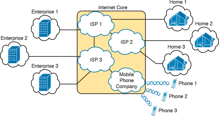
As a network of networks, the Internet is actually owned by countless companies and people. The Internet includes most every enterprise TCP/IP network and a huge number of home-based networks, as well as a huge number of individuals from their phones and other wireless devices, as shown in Figure 3-12.

The middle of the Internet, called the Internet core, exists as LANs and WANs owned and operated by Internet service providers (ISP). (Figure 3-12 shows the Internet core as a cloud, because network diagrams show a cloud when hiding the details of a part of the network.) ISPs cooperate to create a mesh of links between each other in the Internet core, so that no matter through which ISP a particular company or person connects, some path exists to every device.
Figure 3-13 shows a slightly different version of Figure 3-12, in this case showing the concept of the Internet core: ISP networks that connect to both their customers as well as each other, so that IP packets can flow from every customer of every ISP to every other customer of every other ISP.
Internet Access (WAN) Links
The Internet also happens to use a huge number of WAN links. All of those lines connecting an enterprise or home to one of the ISPs in Figure 3-13 represent some kind of WAN link that uses a cable, while the phones create their WAN link using wireless technology. These links usually go by the name Internet access link.
Historically, businesses tend to use one set of WAN technologies as Internet access links, while home-based consumers use others. Businesses often use leased lines, connecting a router at the business to a router at the ISP. The top of Figure 3-14 shows just such an example.

Consumers often use technologies like DSL and cable for Internet access links. These technologies use cabling that is already installed in most homes, making these services somewhat inexpensive for home users. DSL uses the analog phone lines that are already installed in homes, while cable Internet uses the cable TV (CATV) cable.
Note
While DSL and cable are popular with consumers, many businesses use these technologies for Internet access.
All three of the Internet access technologies in Figure 3-14 happen to use a pair of routers: one at the customer side of the WAN link and one at the ISP side. The routers will continue to think about network layer logic, of sending IP packets to their destination by forwarding the packets to the next router. However, the physical and data link layer details on the WAN link differ as compared to leased lines. The next few pages examine both DSL and cable Internet to show some of those differences.
Digital Subscriber Line
Digital subscriber line (DSL) creates a relatively short (miles long, not tens of miles) high-speed link WAN between a telco customer and an ISP. To do so, it uses the same single-pair telephone line used for a typical home phone line. DSL, as a technology, does not try to replace leased lines, which run between any two sites, for potentially very long distances. DSL instead just provides a short physical link from a home to the telco’s network, allowing access to the Internet. First, to get an idea about the cabling, think about typical home telephone service in the United States, before adding DSL service. Each home has one phone line that runs from a nearby telco CO to the home. As shown on the left side of Figure 3-15, the telephone wiring splits out and terminates at several wall plates, often with RJ-11 ports that are a slightly skinnier cousin of the RJ-45 connector.

Next, think about the telephone line and the equipment at the CO. Sometime in the past, the telco installed all the telephone lines from its local CO to each neighborhood, apartment, and so on. At the CO, each line connects to a port on a telco switch. This switch supports the ability to set up voice calls, take them down, and forward the voice through the worldwide voice network, called the public switched telephone network, or PSTN.
To add DSL service at the home in Figure 3-15, two changes need to be made. First, you need to add DSL-capable devices at the home. Second, the telco has to add DSL equipment at the CO. Together, the DSL equipment at each side of the local telephone line can send data while still supporting the same voice traffic.
The left side of Figure 3-16 shows the changes. A new DSL modem now connects to a spare phone outlet. The DSL modem follows the DSL physical and data link layer standards to send data to/from the telco. The home now has a small LAN, implemented with a consumer-grade router, which often includes an Ethernet switch and possibly a wireless LAN access point. (Note that the telephones may now also need a short extra cable with a filter in it, installed at the wall jack, to filter out the sounds of the higher electrical frequencies used for DSL.)
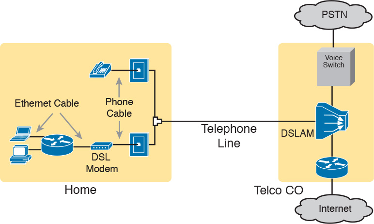
The home-based router on the left must be able to send data to/from the Internet. To make that happen, the telco CO uses a product called a DSL access multiplexer (DSLAM). The DSLAM splits out the data over to the router on the lower right, which completes the connection to the Internet. The DSLAM also splits out the voice signals over to the voice switch on the upper right.
DSL gives telcos a useful high-speed Internet service to offer their customers. Telcos have had other offerings that happen to use the same telephone line for data, but these options ran much slower than DSL. DSL supports asymmetric speeds, meaning that the transmission speed from the ISP toward the home (downstream) is much faster than the transmissions toward the ISP (upstream). Asymmetric speeds work better for consumer Internet access from the home, because clicking a web page sends only a few hundred bytes upstream into the Internet, but can trigger many megabytes of data to be delivered downstream to the home.
Cable Internet
Cable Internet creates an Internet access service which, when viewed generally rather than specifically, has many similarities to DSL. Like DSL, cable Internet takes full advantage of existing cabling, using the existing cable TV (CATV) cable to send data. Like DSL, cable Internet uses asymmetric speeds, sending data faster downstream than upstream, which works better than symmetric speeds for most consumer locations. And like DSL, cable Internet does not attempt to replace long leased lines between any two sites, instead focusing on the short WAN links from a customer to an ISP.
Cable Internet also uses the same basic in-home cabling concepts as does DSL. Figure 3-17 shows a figure based on the earlier DSL Figure 3-16, but with the DSL details replaced with cable Internet details. The telephone line has been replaced with coaxial cable from the CATV company, and the DSL modem has been replaced by a cable modem. Otherwise, the details in the home follow the same overall plan.

On the CATV company side of the cable Internet service, the CATV company has to split out the data and video, as shown on the right side of the figure. Data flows to the lower right, through a router, while video comes in from video dishes for distribution out to the TVs in people’s homes.
Cable Internet service and DSL directly compete for consumer and small-business Internet access. Generally speaking, while both offer high speeds, cable Internet typically runs at faster speeds than DSL, with DSL providers keeping their prices a little lower to compete. Both support asymmetric speeds, and both provide an “always on” service, in that you can communicate with the Internet without the need to first take some action to start the Internet connection.
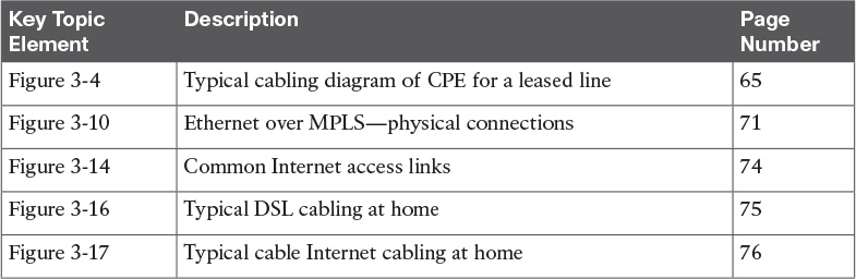
Chapter Review
One key to doing well on the exams is to perform repetitive spaced review sessions. Review this chapter’s material using either the tools in the book, DVD, or interactive tools for the same material found on the book’s companion website. Refer to the “Your Study Plan” element section titled “Step 2: Build Your Study Habits Around the Chapter” for more details. Table 3-4 outlines the key review elements and where you can find them. To better track your study progress, record when you completed these activities in the second column.