
Part Three. MPEG International Standards
| 7 MPEG 2 Systems |
| 8 MPEG 2 Video Compression |
| 9 MPEG 1 Audio Compression |
Foreword
The second work item of the Moving Picture Experts Group (MPEG), popularly known as MPEG 2, was developed to deal with full-resolution pictures and multichannel audio. The Direct Broadcast Satellite (DBS) was certainly one of the major target applications.
In July 1990 at the MPEG meeting in Porto, Portugal, we began the effort to develop the MPEG 2 standard. It was at this meeting that I first met Don Mead, who was representing Hughes Electronics. Hughes had begun a program called Sky Cable (later named DIRECTV) and had issued a request for information (RFI) to the industry to provide information about the DBS requirements. Because of the technical relevance of the RFI it was agreed that this document should be entered as an official MPEG document for the Porto meeting so that the MPEG members could take into account that throughout the three years of very intense effort to develop the MPEG 2 standard, Dr. Mead was intimately involved. He made particular contributions to the program management aspects. He was in perfect agreement with me about the need to ensure that the standard stayed on track for meeting its scheduled obligations, particularly on the requirements and systems subgroups.
The three chapters of Part Three of this book show the particularization of MPEG 2 to the DBS requirement. In them you will find all the information required to understand the application of MPEG to DBS.
Clearly, MPEG 2 and DBS were synergistic: DBS created a market for digital television (i.e., for MPEG 2), while MPEG 2 was the enabling technology for DBS.
I am confident that you will find this part of the book both stimulating and instructive.
Leonardo Chiariglione
MPEG Convenor, ISO/IEC
JTC1/SC29/WG11
The Need for Standards
Most people are not aware of the effect technical standards have on their everyday lives. Consumers in the United States can go to a store and buy a television set from any number of manufacturers and be assured that when they take it home, both the set and the terrestrial broadcast or cable signals will be received and understood by the set they bought. This is because long ago an organization called the National Television Systems Committee established the standard that goes by its name—NTSC. Similarly, fax transmission was around for many years but was prohibitively expensive. In 1979, I remember wanting to send an electronic schematic from New York to a field engineer in Ireland, and Western Union was more than happy to do so for $2,500. It was cheaper to take the schematic in hand, fly to Ireland, and hand it to the field engineer than to send it by fax. It was not until the Group 3 facsimile standard was established and faxes could be received on any Group-3-compatible machine that faxing really took off. Quick standardization also permitted the rapid growth of the compact disc.
Standards Bodies
Standards are established by a very large number of bodies. However, three of them are important for the purposes of this book.
1. The International Telecommunications Union (ITU) is a United Nations chartered body. The ITU has two main arms: the ITU-R, which is the standards-setting body for radio, and the ITU-T, which is the standards-setting body for telecommunications. The members of the ITU are the national ministries of telecommunication and posts. Since the United States does not have a ministry of telecommunication and posts, the State Department serves as the U.S. representative.
2. The second major international standards-setting body is the International Standards Organization (ISO), which has its headquarters in Geneva, Switzerland. While the ITU has specialized in telecommunications standards, the ISO has tended to specialize in information technology (although ISO 9000, the standard for quality control, is probably its most famous standard).
3. The American National Standards Institute (ANSI) represents the United States in the ISO. Also, the State Department usually delegates ANSI as its representative for ITU functions. ANSI has the responsibility for developing U.S. national positions on standards activities and, in the case of ISO, of providing the delegate rosters.
International Standards Organization
Figure P3.1 shows the organization of ISO with regard to the Moving Picture Experts Group (MPEG). In conjunction with the International Electrotechnology Commission (IEC), ISO has formed the Joint Technical Committee 1 (JTC 1) for information systems. This is the top organization within the ISO standards-making hierarchy.
Figure P3.1 The Moving Picture Experts Group in the ISO

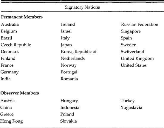
Table P3.1 shows the membership of JTC 1. Note that the 26 P members are official voting members, whereas the 10 O members are observers. Reporting to JTC 1 is Subcommittee 29 (SC 29), which is responsible for picture coding efforts. In the early days of MPEG, what is now SC 29 was Subcommittee 2. Finally, the Moving Picture Experts Group is Working Group 11 of SC 29. It should be noted that the Working Group 11 took its number when it was part of SC 2. Thus, not all of the numbers between 1 and 12 exist.
Table P3.1 Permanent and Observer Members of JTC 1
MPEG History
In the mid-to-late 1980s it became apparent that video was going to go digital. It also was clear that if international standards were not developed for digital video, there would be a ‘Tower of Babel’ as proprietary standards proliferated; therefore, in 1988 ISO chartered MPEG, Working Group 11, to develop standards for digital video. The following three work items were defined:
1. Video and associated audio at rates up to about 1.5 Mbps (later called MPEG 1)
2. Moving pictures and associated audio at rates up to about 10 Mbps (later called MPEG 2)
3. Moving pictures and associated audio at rates up to about 60 Mbps (later reduced to 40 Mbps and then cancelled)
MPEG 1 was oriented toward digital video stored on digital storage media (DSM). MPEG 2 was oriented toward broadcast media. MPEG 3 was for high-definition television (HDTV). As work progressed on the development of the standards, especially about the time that MPEG 1 was being completed and MPEG 2 was really in the mainstream, it became clear that the techniques employed in the standards could be used at any bitrate. While it was optimized around 1.5 Mbps, MPEG 1 could be used at very high bitrates. MPEG 2 could be used at virtually any bitrate.
Then a significant debate arose within the MPEG community as to whether to change the title of MPEG 2 by eliminating the 10 Mbps statement in its title. The U.S. delegation was able to convince its MPEG colleagues to do this, and the 10 Mbps was dropped from the MPEG 2 title. At the same time it was clear that the MPEG 2 could satisfy the needs of what originally had been thought would be a separate standard required for HDTV. Therefore, MPEG 3 was dropped and will never exist.
When the consortia of companies in the United States called the Grand Alliance selected a Video Compression standard for the U.S. HDTV service, they picked MPEG 2 video. This justifies the decision that MPEG 2 could provide the compression for HDTV.
MPEG Background
In 1988 the MPEG, Working Group 11, was formed under the convenorship of Dr. Leonardo Chiariglione of CSELT in Italy. The efforts of this group culminated in November 1992 when ISO Standard 11172, Parts 1, 2, and 3 were approved. The parts of the standard are as follows:
Part 1—Systems. This is the transport and multiplex layer, which provides for synchronization of the audio and video bitstreams.
Part 2—Video compression
Part 3—Audio compression
It should be noted that the three parts of the ISO standard are published in a stand-alone fashion so that each can be used by itself as well as with the other two parts.
The MPEG 2 effort was kicked off in July 1990 at the MPEG meeting in Portugal. It became ISO Standard 13818, Parts 1,2, and 3, in November 1994 at the meeting in Singapore. The first three parts of MPEG 2 cover the same subjects as MPEG 1.
The first two chapters of Part Three of this book are based on MPEG 2. For reasons explained in Chapter 9, the Audio Compression Standard described is from MPEG 1. Copies of ISO Standards 11172 and 13818 can be obtained by contacting either of the following:
International Standards Organization, 1 Rue de Varembe, Case Postale 56, CH-1211, Geneva 20, SWITZERLAND (Tel: 22-749-0111). Document Engineering Co., Inc. (DECO), 15210 Stagg Street, Van Nuys, CA 91405-1092 U.S.A.
Chapter Seven. MPEG 2 Systems
Part 1 of both ISO 11172 (MPEG 1) and ISO 13818 (MPEG 2) is called ‘Systems.’ It is easy to see the need for Video Compression (Part 2 in each standard) and Audio Compression (Part 3 in each standard); however, what is Systems, and why is it needed?
7.1 The Role of MPEG Systems
The video, audio, and other data for an MPEG-coded service must be multiplexed into a single bitstream. This is the first task of MPEG 2 Systems.
Next, the question is, when the multiplexer is receiving separately compressed video and audio bitstreams, how are they to be multiplexed so that the decoder can present them in a synchronized manner (for example, lip synchronization between audio and video)? A second role of Systems is to provide the means for such synchronization.
Even though MPEG bitstreams represent a continuous stream of bits, the bits need to be organized into groups (packets) so that bit errors cannot propagate beyond the borders of a single packet. In general, the longer the packet length, the more susceptible it is to bit errors. On the other hand, grouping the bits into packets creates overhead to accommodate the packet headers. In general, the shorter the packet length, the higher the overhead. There is, thus, a tradeoff in selecting a packet length between error resiliency and efficiency. In any event, forming the packets is a third function of MPEG Systems.
In most cases, decoders require Program Specific Information (PSI) to decode the arriving bitstream. Providing this PSI is MPEG Systems’ fourth role. In summary then, MPEG Systems:
1. Multiplexes individual bitstreams into a single bitstream
2. Provides the means to synchronize the component bitstreams that create an audio and/or video service
3. Packetizes the bits into groups
4. Provides PSI
In MPEG 2 Systems, a program is defined as a set of meaningful Elementary Streams, such as audio and video, that have the same time base.
7.2 Transport Stream
Transport Streams are composed of Transport Stream packets with headers containing information that specifies the time when each byte is intended to enter a Transport Stream Decoder from the channel.
Through an additional multiplex-wide operation, a decoder is able to establish what resources are required to decode a Transport Stream. The Transport Stream contains information that identifies the pertinent characteristics and relationships between the Elementary Streams that constitute each program. Such information may include the language spoken in audio channels, as well as the relationship between video streams when multilayer video coding is implemented.
Figure 7.1 illustrates how a Transport Stream is constructed in two layers: a system layer and an elementary stream (ES) layer. The Transport Stream encoder wraps a system layer about an ES layer.
Figure 7.1 MPEG 2 Systems Transport Stream Encoding

The structure of a Transport Stream packet creates a number of design decisions. On one hand, the length of the packer header wants to be as small as possible in order to minimize the header overhead. On the other hand, the control features want to be as rich as possible, which implies a long header.
MPEG 2 Systems is able to achieve both of these seemingly contradictory objectives in the following manner:
• For the delivery of payload data, a fixed four-byte header is used. However, 2 bits (out of the 32) identify whether the information in the packet is payload data, or an Adaptation field.
• If an Adaptation field is indicated, a number of special parameters can be included in the packet payload. Since Adaptation fields are sent infrequently, the effect on the overall header efficiency is minimal. The Adaptation field itself is hierarchical in that it contains several additional sublayers of Adaptation fields.
Transport Streams are an envelope for constituent ESs. However, the Elementary Streams are usually not independent of each other. For example, an audio and/or video service will have an audio ES and a video ES. These two Elementary Streams are associated and are called a program, not unlike the language we would use for a ‘TV program.’ The constituent ESs of each program must have the same time base.
Elementary Stream data is carried in Packetized Elementary Stream (PES) packets. A PES packet consists of a PES packet header followed by data. Packetized Elementary Stream packets are inserted into Transport Stream packets. The first byte of each PES packet header is located at the first available payload location of a Transport Stream packet. A discussion of the PES packet structure is contained in a separate section that follows.
The Program Specific Information tables are carried in the Transport Stream. There are four PSI tables:
• Program Association Table
• Program Map Table
• Conditional Access Table
• Network Information Table
These tables contain information needed to demultiplex and present programs. The Program Map Table specifies other information about which packet IDs (PIDs), and, therefore, which Elementary Streams are associated to form each program.
7.2.1 Packet Length
Because its main use was intended to be with digital storage media (DSM) with attendant very low error rates, MPEG 1 Systems permitted very large (and variable) packet lengths. MPEG 2 Program Streams are designed for the same type of applications. On the other hand, one of the main applications for MPEG 2 was broadcast and other error-prone transport. Thus, the Transport Stream part of MPEG 2 Systems is appropriate for DBS and is covered in the remainder of this chapter.
The Transport Stream is comprised of a sequence of fixed-length packets of 188 bytes each. Note that 188 bytes is not an obvious length unless several special factors are considered. In a shortened Reed-Solomon block error-correction code, 188 is a natural size for the number of information bytes. To see this, recall that a t error-correcting Reed-Solomon code is defined by
Block length: n = q - 1
Number of parity check digits: n – k = 2 * t
Minimum distance: d min = 2 * t + 1
If we let q - 28 = 256, then n = 255. If we further let t = 8 so that eight bytes worth of errors can be corrected, a (255, 239) code results. This has been a U.S. National Aeronautics and Space Administration (NASA) standard Reed-Solomon code for a number of years. We can form a code with n´ = n - 1 and k´ = k - 1, which is known as a shortened Reed-Solomon code. By letting l = 51, a shortened Reed-Solomon code (204,188) results.
A (204,188) Reed-Solomon code is used for the Digital Video Broadcast (DVB) standard, for example. It will correct eight byte errors in each 204-byte packet. Thus, there is no overhead (other than the parity bytes) from the 188 information bytes to the 204 total bytes after application of the outer code.
The second reason for the 188 arises from the length of Asynchronous Transfer Mode (ATM) packets. Figure 7.2 shows the ATM packet structure. The structure consists of a 5-byte header, a 1-byte ATM Adaptation Layer (AAL), and a 47-byte payload. Since 4 * 47 = 188, an MPEG 2 Transport Packet maps into four ATM packets with no overhead.
Figure 7.2 ATM Packet Structure

7.2.2 Transport Stream Rate
The Transport Stream defines a bitstream that is optimized for communicating or storing one or more programs of MPEG 2 coded data and other data for error-prone environments. The Transport Stream rate is defined by the values and locations of Program Clock Reference (PCR) fields.
Generally, there are separate PCR fields for each program. A single Transport Stream may contain a number of such programs, each with a different time base. Note that this is necessary for DBS because the program materials that are multiplexed into a Transport Stream for a particular transponder arrive at the uplink site in a wide variety of ways. Each DBS transponder has a fixed bandwidth, so the Transport Stream bit rate is constant for each transponder.
7.2.3 Transport Stream Packet Header
![]()
The Transport Stream Packet Header contains all of the information required by a decoder to decode the various packet structures. Figure 7.3 shows the overall structure. Referring to this figure, the Transport Stream packets can contain three types of payloads: Packetized Elementary Streams, Program Specific Information, and Adaptation fields. Only one of these packet types can be the payload at any one time (there is one exception, but it is of minor importance). The PSI packets are composed of four different types of packets. Once again, only one is present in a particular Transport Stream packet. Each of the three payload types can carry private data.
Figure 7.3 Transport Stream Header Structure

It is instructive to follow through on how a decoder can parse the Transport Stream Header. First, the adaptation_field_control field is checked to see if it is 2 or 3. If it is, the decoder knows that the packet contains an Adaptation field, and starts to further parse it. If the adaptation_field_control is 1 or 3, the decoder continues to parse the Transport Stream Header to determine whether PES or PSI data is contained in this packet. If, at this point in the decoding, the adaptation_field_control is not 1 or 3, the packet is discarded as not containing useful data.
Assuming then that the adaptation_field_control is 1 or 3, the decoder determines whether the PID value is for PES or PSI. Either the PES or PSI payload types can carry Private data. If the packet is an Adaptation field, the transport_private_data_flag is checked. If it is a’1’, the packet is carrying Private data. If ‘0’, the packet is carrying another type of Adaptation field.
The following list discusses the constituents of the Transport Stream Packet Header.
All packets contain sync bytes which allow the decoder to synchronize to the bitstream. The sync_byte value is ‘0100 0111’ (0x47)—remember that the notation Ox means hexadecimal. Sync byte emulation in the rest of the bitstream should be avoided.
When the bitstream contains at least one uncorrectable bit error, the transport_error_indicator is set to ‘1’.
The payload_unit_start_indicator is a 1-bit flag that has a specific meaning for Transport Stream packets that carry PES packets or PSI data. When this flag is set (a ‘1’), this packet contains the first byte of a PES packet, or the first byte of a PSI section. If not set, it does not carry such a byte. When a Transport Packet contains PSI data and the packet_unit_start_indicator is ‘1’, the first byte after the header is a pointer_field.
The pointer_field (PSI payload only) is an 8-bit field whose value is the number of bytes immediately following the pointer_field until the first byte of the first section in the payload of that packet (so a value of 0x00 in the pointer_field indicates that the section starts immediately after the pointer_field).
Packets with the transport_priority set to‘1’ indicate that the packet is of greater priority than other packets with the same PID that has this flag set to‘0’.
The PID is a 13-bit field that identifies the packet payload. PID values for the Program Association Table and the Conditional Access Table are specified. Other PID values are reserved.
The transport_scrambling_control (a better name would be transport_ encryption_control), 2-bit field indicates the encryption mode of the Transport Stream Packet payload. Transport Stream Packet Headers, including the Adaptation field when present, cannot be encrypted.
The adaptation_field_control indicates whether this Transport Stream Packet Header is followed by an Adaptation field and/or a payload.
Packets with the same PID are counted by a 4-bit counter and presented in the Transport Stream Header as the continuity_counter. The 4-bit counter wraps around to ‘0’ after it reaches ‘1111’. The continuity_ counter cannot be incremented when the payload is an Adaptation field.
When the discontinuity_counter state is true in any Transport Stream packet, the continuity_counter in the same packet may be discontinuous with respect to the previous Transport Stream packet of the same PID.
7.2.4 Timing Model
MPEG 2 Systems, Video, and Audio all have a timing model in which the end-to-end delay from the signal input to an encoder, to the signal output from a decoder, is a constant. This delay is the sum of all the delays from encoding to presentation. The inter-Picture interval and audio sample rate are the same at the decoder as at the encoder.
7.2.5 Conditional Access
Chapter 6 noted the importance of Conditional Access (CA) for a DBS system, so MPEG 2 Systems must support CA. Encryption for Conditional Access to programs is encoded in the Transport Stream in MPEG 2 Systems. Elements of the standard provide specific support for such systems.
7.2.6 Multiplex-wide Operations
Multiplex-wide operations include the coordination of data retrieval off the channel, clock adjustment, and buffer management. In general, for the broadcast case, Elementary Stream decoders must slave their timing to the data received from the channel to avoid overflow or underflow of decoder buffers.
7.2.7 Transport Stream System Target Decoder
A hypothetical decoder known as the Transport Stream System Target Decoder (T-STD) is used to define timing. Byte arrival and decoding event timing are set out in MPEG 2 Systems. A detailed discussion of the timing model of the T-STD is beyond the scope of this book. For more details, refer to section 2.4.2 of ISO/IEC 13818-1.
Payload (non-Adaptation field): The payload of a Transport Packet consists of data from the PES packets, PSI sections, or Private data that are labeled in the standard data_bytes.
7.3 Individual Stream Operations (PES Packet Layer)
Demultiplexing and synchronizing playback of multiple Elementary Streams are the principal stream-specific operations.
7.3.1 Demultiplexing
Elementary Streams are multiplexed into Transport Streams. Audio and video streams are the primary ESs. Only one Elementary Stream may be in a PES packet. PES packets are normally relatively long. Packet ID codes in the Transport Stream permit the decoding and demultiplexing required to reconstitute ESs.
7.3.2 Synchronization
Time stamps allow synchronization among multiple Elementary Streams. The System Clock Reference (SCR), the Program Clock Reference (PCR), and the optional Elementary Stream Clock Reference (ESCR) have extensions with a resolution of 27 MHz. Because presentation time stamps apply to the decoding of individual ESs, they reside in the PES packet layer of Transport Streams.
The PCR time stamp allows synchronization of a decoding system with the channel. The PCR time stamp encodes the timing of the bitstream itself and is derived from the same time base used for the audio and video. Because each program may have its own time base, there are separate PCR fields for each program in a Transport Stream that has multiple programs. A program can have only one PCR time base associated with it.
7.3.3 Relation to Compression Layer
While compressed audio and video Elementary Streams contain their own information for decoding, these streams are the payloads for PES packets. The PES packets do not concern themselves with the nature of the payload. For example, video start codes can occur in the middle of a PES packet. However, time stamps encoded in PES Packet Headers apply to presentation times of compression layer constructs (namely, presentation units).
7.3.4 PES Packets
Packetized Elementary Stream
Transport Streams for multimedia content are logically constructed from Packetized Elementary Stream packets, as indicated in Figure 7.1. Elementary Stream Clock Reference fields and Elementary Stream Rate (ES_Rate) fields must be included in PES packets. PES packets are the dominant form of Transport Packet payload. The structure of these packets is discussed in the following section.
PES Packet Structure
PES packets start with a Packet Header. The header for PES packets is much longer and more involved than the other headers in MPEG 2 Systems because they must provide a great deal of information regarding the constituent elementary streams. This book discusses the more important header parameters and summarizes the remainder. For full details the reader is referred to the ISO standard.
As with most packets, the first parameter is a sync or start_code.
The packet_start_code_prefix is the bit string—’0000 0000 0000 0000 0000 0001’ (0x000001). As usual, care should be taken not to emulate the start code in the remainder of the packet.
The stream_id specifies the type and number of the Elementary Streams and may take values in the range OxBC to OxFF. The value OxBC signifies the Program_Stream_Map. All IDs that start with OxC and OxD are used for audio streams. OxE IDs are used for video streams and OxFO and OxFl IDs are used for Entitlement Control Messages (ECM) and Entitlement Management Messages (EMM).
The PES_packet_length is a 16-bit field specifying the number of bytes in the PES packet. Thus, a PES packet could be 65,536 bytes long.
The PES_scrambling_control is a 2-bit field that indicates the scrambling mode of the PES packet payload. Once again, encryption control would have been a better name.
The next 11 parameters in the header are the flags: PES_priority, data_ alignment_indicator, copyright, original_or_copy, PTS_DTS_flags, ESCR_ flag, ES_rate_flag, DSM_trick_mode_flag,1 additional_copy_info_flag, PES_CRC_flag, and PES_extension_flag. All these parameters are 1-bit flags, indicating the presence or absence of a condition, except for PTS_DTS_ flags, which is 2 bits. Table 7.1 explains PTS_DTS_flags.
1 In MPEG a ‘trick mode’ is a mode usually associated with a digital storage medium. Thus, fast forward, slow motion, rewind, and so on, are trick modes.
Table 7.1 What PTS_DTS_flags Mean

If the PES_extension_flag is ‘1’, the PES_header_data_length 8-bit field specifies the total number of bytes occupied by the optional fields and any stuffing bytes contained in this PES Packet Header. The marker_bit is a 1-bit flag that always has the value ‘1’.
The next three parameters are the various time stamps (if present): PTS (presentation_time_stamp), DTS (decoding_time_stamp), and ESCR (elementary_stream_clock_reference). The PTS and DTS indicate the time for presentation and decoding. They are 33-bit numbers that are measured in the number of 27-MHz clock periods divided by 300. The ESCR is a 42-bit value comprised of a 33-bit base (ESCR_base) and a 9-bit extension (ESCR_ext). The base is measured in periods of a 90-kHz clock.
The ES_rate (elementary_stream_rate) field is a positive integer specifying the PES stream rate.
trick_mode_control is a 3-bit field that indicates which trick mode is applied to the associated video stream. Since trick modes are not applicable for DBS, they are not discussed further here.
field_id is a 2-bit field that indicates which field(s) are to be displayed in trick modes. This is not relevant for DBS.
In MPEG 2 Video, a Macroblock is a 16-by-16 pixel Block (Y axis). If some Macroblocks may be missing, intra_slice_refresh is set to ‘1’. This knowledge can be used for error concealment.
The 2-bit frequency_truncation field can indicate that a restricted set of coefficients may have been used in coding the video data.
field_rep_cntrl is a 5-bit field that indicates certain display parameters in Video trick modes. Not applicable for DBS.
The additional_copy_info is a 7-bit field that contains Private data relating to copyright information.
The previous_PES_packet_CRC is a 16-bit CRC (see Appendix E).
There then follow five 1-bit flags: PES_private_data_flag, packet_ header_field_flag, program_packet_sequence_counter_flag, P-STD_buffer_ flag, and PES_extension_flag_2. These flags indicate the presence or absence of the indicated condition.
Private data in a PES packet is carried in PES_private_data, a 16-bit field. This data must not emulate the packet_start_code_prefix (0x000001).
The length, in bytes, of the packet_header_field is indicated by the 8-bit field packet_field_length.
The PES packets of a particular program are counted by the 7-bit program_packet_sequence_counter.
The remainder of the header parameters—MPEGl_MPEG2_identifier, original_stuff_length, stuffing_byte, P-STD_buffer_scale [Program Stream only], and PES_extension_field_length—are not important for DBS.
PES Data Packets
The PES_packet_data_bytes are contiguous bytes of data from the ES indicated by the packet’s stream_id or PID. The padding_byte is a fixed 8-bit value equal to ‘1111 1111’. The decoder discards it.
7.4 Program Specific Information
![]()
Program Specific Information includes both MPEG 2 Systems required data and Private data that enable demultiplexing of programs by decoders. programs or Elementary Streams, or parts of them, may be conditionally accessed. However, Program Specific Information cannot be encrypted.
In Transport Streams, PSI consists of four table structures. The tables that comprise PSI packets have a very similar structure, as shown in Table 7.2. Common fields are in bold. Fields unique to a particular table are in regular type.
Table 7.2 PSI Table Parameters with Common Items Indicated (in Bold)

7.4.1 Common Field Types
Because a number of field types are common to all four tables, 2 they will be described first. Then, the fields unique to each table are discussed.
2 In discussing common fields, the description uses the language for the Program Association Table (PAT). In this common section, it applies to all of the relevant tables.
The table_id is an 8-bit field that identifies the content of a Transport Stream PSI section, as follows: 0x00 defines the program_association_ section; 0x01 defines the conditional_access _section; 0x03 to 0x3F are reserved; 0x40 to 0xFE are User Private; and 0xFF is forbidden.
The section_syntax_indicator is a 1-bit field that must be set to ‘1’.
The section_length is a 12-bit field, the first two bits of which are ‘00’. It specifies the number of bytes of the section, starting immediately following it, including the CRC.
The version_number is a 5-bit field that is the version number of the Program Association Table. Whenever the definition of the Program Association Table changes, the version number is incremented by one. When the value 31 is reached, it wraps around to ‘0’. The current_next_ indicator determines whether the version_number is that of the currently applicable Program Association Table or that of the next applicable PAT.
The current_next_indicator is a 1-bit field that, when set to ‘1’, indicates that the PAT sent is currently applicable. When the bit is set to ‘0’, it indicates that the table sent is not yet applicable and will be the next table to become valid.
The section_number is an 8-bit field that gives the number of the current section. The last_section_number is an 8-bit field that specifies the number of the last section (the section with the highest section_number) of the complete Program Association Table.
CRC_32—This field is 32-bit with various CRC values (see appendix E).
7.4.2 Program Association Table
![]()
All Transport Streams contain one or more Transport Stream packets with a PID value of 0x0000. These Transport Stream packets together contain a complete list of all programs within the Transport Stream. Any changes in the programs carried within the Transport Stream are described in an updated version of the Program Association Table carried in Transport Stream packets with PID value 0x0000. These sections use table_id value 0x00. Only sections with this value of table_id are permitted within Transport Stream packets with a PID value of 0x0000.
The maximum number of bytes in a section of an MPEG 2 Systems-defined PSI table is IK (1,024 bytes). The maximum number of bytes in a private_ section is 4K (4,096 bytes). There are no restrictions on the occurrence of start codes, sync bytes, or other bit patterns in PSI data, whether MPEG 2 Systems or Private.
The Program Association Table provides the correspondence between a program_number and the PID value of the Transport Stream Packets that carry the program definition. The program_number is the numeric label associated with a program. Program number 0x0000 is reserved to specify the network PID. This identifies the Transport Stream packets that carry the Network Information Table.
Definition of Unique Fields in PAT Section
A Transport Stream can be separated from any other multiplex within a network by the transport_stream_id, a 16-bit field.
The program to which the program_map_PID is applicable is set by the 16-bit program_number. If this is set to 0x0000, then the following PID reference must be the network PID. The program_number may be used as a designation for a broadcast channel, for example.
The network_PID (optional) is a 13-bit field that specifies the Network Information Table.
The Transport Stream packets that must contain the program_map_ section applicable for a program is specified by the 13-bit program_ map_PID field.
7.4.3 Program Map Table
![]()
All Transport Streams must contain one or more Transport Stream packets with PID values that are labeled under the Program Association Table as Transport Stream packets containing Program Map sections. Every program listed in the PAT is described in a single Transport Stream Program Map section.
The most recently transmitted version of the TS_program_map_section with the current_next_indicator set to a value of ‘1’ always applies to the current data within the Transport Stream. Any changes in the definition of any of the programs carried within the Transport Stream are described in an updated version of the corresponding section of the Program Map Table carried in Transport Stream packets with the PID value identified as the program_map_PID for that specific program. During the continuous existence of a program, including all of its associated events, the program_ map_PID cannot change.
Sections with a table_id value of 0x02 contain Program Map Table information. Such sections may be carried in Transport Stream packets with different PID values.
A program definition is a mapping between a program number and the Elementary Streams that comprise it. The Program Map Table provides the complete collection of all program definitions for a Transport Stream. The table may be segmented into one or more sections, before insertion into Transport Stream packets.
Definition of Unique Fields in Transport Stream Program Map Section
program_number (see Program Association Table description).
The PCR fields valid for the program specified by program_number must be identified by a 13-bit PCR_PID.
The number of bytes of the descriptors are indicated by the 12-bit program_info_length, 3 the first two bits of which must be ‘00’.
3 For information on the ES_info_length field, see program_info_length.
The type of ES or payload specified by the elementary_PID is indicated by the 8-bit stream_type field.
The PID of the Transport Stream packets that carry the associated Elementary Stream or payload is indicated by the 13-bit elementary_PID.
Elementary Stream Descriptors
Elementary Stream Descriptors provide additional information about the ESs. All stream descriptors have a format that begins with an 8-bit tag value. The tag value is followed by an 8-bit descriptor length and data field.
Stream Descriptors
The 8-bit fields—descriptor_tag, which identifies each descriptor, and descriptor_length, which specifies the number of bytes of the descriptor immediately following the descriptor_length field—are common to all stream descriptors.
Although the 8-bit structure of the stream tag would allow for 256 descriptors, only 13 are used. Tag values 2 (video_stream_descriptor), 7 (target_ background_grid_descriptor), and 8 (video_window_descriptor) all describe attributes of Video streams.
Video Stream Descriptors
The video_stream_descriptor identifies key parameters of the video ES. In particular, the frame rate code is identified. The profile and level are also indicated (see Chapter 8), along with other parameters.
The target_background_grid_descriptor describes how to place the video display when the display area is larger than the video being transported.
The video_window_descriptor is used to describe the window characteristics of the associated ES. Its values reference the target_background_ grid_descriptor for the same stream.
Audio Stream Descriptor (tag value 3)
The audio_stream_descriptor provides basic information that identifies the coding version of an audio ES.
Registration Descriptor (tag value 5)
The registration_descriptor provides a method to uniquely and unambiguously identify formats of private data. It includes a 32-bit value obtained from a registration authority as designated by ISO.
Conditional Access Descriptor (tag value 9)
If any systemwide Conditional Access management information exists within a Transport Stream, a CA_descriptor must be present in the appropriate map section. This descriptor is used to specify both systemwide CA management information—EMMs and ES-specific information such as ECMs.
When the CA_descriptor is in the TS_program_map_section (table-id = 0x02), the CA_PID points to packets containing program-related access control information such as ECMs. When the CA_descriptor is found in the CA_section (table-id = 0x01), the CA_PID points to packets containing systemwide and/or access control management information such as EMMs.
ISO 639 Language Descriptor (tag value 10)
ISO 639 Part 2 defines a 3-character code for languages. The ISO_639_ language_descriptor can be used to specify the language of the associated ES.
System Clock Descriptor (tag value 11)
This descriptor conveys information about the system clock that was used to generate the time stamps. The clock frequency accuracy is
clock_accuracy_integer * 10-clock_accuracy_exponent ppm
where clock_accuracy_integer is 6 bits and the clock_accuracy_exponent is 3 bits.
If an external clock reference was used, the external_clock_reference_ indicator is set. If the system clock is more accurate than the 20-ppm accuracy required, then the accuracy of the clock can be communicated by encoding it in the clock_accuracy fields.
If clock_accuracy_integer = 0, the system clock accuracy is 20 ppm. When both parts of the descriptor are used, the clock accuracy pertains to the external reference clock.
Copyright Descriptor (tag value 13)
The copyright_descriptor contains a copyright_identifier that is a 32-bit value obtained from a Registration Authority as designated by ISO.
Maximum Bitrate Descriptor (tag value 14)
The maximum_bitrate_descriptor is coded as a 22-bit positive integer in the field expressing the maximum bit rate in units of 50 bytes per second.
7.4.4 Conditional Access Table
Transport Stream packets must convey the appropriate CA_descriptors whenever one or more ESs within a Transport Stream are encrypted. Transport Stream packets with a PID value 0x0001 contain these descriptors. A complete version of the Conditional Access Table must be maintained in the decoder. When the current_next_indicator is ‘1’, that table is applied to the encrypted files in the Transport Stream. Any changes in encryption making the existing ISO table invalid or incomplete are described in an updated version of the Conditional Access Table. All these sections use a table_id value of 0x01. Only sections with this table_id value are permitted within Transport Stream packets with a PID value of 0x0001.
The Conditional Access Table provides the association between one or more CA systems, their EMM streams, and any special parameters associated with them. Conditional Access fields only use the common fields.
7.4.5 Network Information Table
The Network Information Table is optional and its contents are Private. If present, it is carried within Transport Stream packets that have the same PID value, called the network_PID. The network_PID value is defined by the user and, when present, is found in the Program Association Table under the reserved program_number 0x0000. If the Network Information Table exists, it takes the form of one or more private_sections.
7.4.6 Syntax of the Private Section
![]()
In addition to defined PSI tables, it is possible to carry Private data tables. These may be structured in the same manner used for defined PSI tables so that the syntax for mapping this Private data is identical to that used for the mapping of a defined PSI table. For this purpose, a Private section is defined. If the Private data is carried in Transport Stream packets with the same PID value as Transport Stream packets carrying Program Map Tables (as identified in the PAT), then the private_section syntax and semantics are used.
A Private table may be made of several private_sections, all with the same table_id.
7.5 Adaptation Field
Recall that the Adaptation field is signaled by a 2-bit flag in the Transport Packet Header. By sending infrequently changing parameters in this manner, rich collateral information can be conveyed without substantially reducing overall header efficiency.
The first parameter in the Adaptation field is the adaptation_field_ length, an 8-bit field specifying the number of bytes in the Adaptation field immediately following it.
The discontinuity_indicator is a 1-bit field that, when set to ‘1,’ indicates that the discontinuity state is true and that the PCR, which is a sample of the system_clock_frequency for that program, is about to change. When the discontinuity state is true for a Transport Stream packet that contains a PCR_PID, the next PCR in a Transport Stream packet with the same PID represents the new clock frequency.
These are the 8 1-bit flags that follow: discontinuity_indicator, random_ access_indicator, elementary_stream_priority_indicator, PCR_flag, OPCR_ flag, splicing_point_flag, transport_private_data_flag, and adaptation_ field_extension_flag. As usual with such flags, they indicate the presence or absence of a particular condition.
The discontinuity_indicator being set means the PCR is going to be updated.
The random_access_indicator being set means that the next PES packet contains either the first byte of a video sequence header or the first byte of an audio frame.
When the PCR_flag is set, a new, two-part PCR is contained in this Adaptation field. This PCR is a 42-bit field coded in two parts.
program_clock_reference_base is a 33-bit field in units of 1/300 multiplied by the system clock frequency (90 kHz).
The program_clock_reference_extension is a 9-bit field in units of system clock frequency (27 MHz).
The following are not important for DBS: original_program_clock_ reference_base and original_program_clock_reference_extension.
splice_countdown is not important for DBS.
The private_data_length is an 8-bit field specifying the number of private_data bytes immediately following it.
The private_data_byte is an 8-bit field that shall not be specified by ISO/IEC.
The adaptation_field_extension_length is an 8-bit field that indicates the length of the extended Adaptation field data that follows it.
There then follow 4 more 1-bit flags: ltw_flag (legal_time_window_ flag), piecewise_rate_flag, seamless_splice_flag, and ltw_valid_flag (legal_ time_ window_valid_flag). As usual, these flags indicate the presence or absence of a condition.
ltw_offset (legal_time_window_offset) is a 15-bit field that is part of T-STD timing.
piecewise_rate is a 22-bit field that is a positive integer specifying the bit rate over all transport packets of this PID, starting with the packet containing this field and continuing until the next occurrence of this field. The value of the piecewise_rate is measured in units of 50 bytes per second. A value of ‘0’ is forbidden.
splice_type is not important for DBS.
The DTS_next_au (decoding_time_stamp_next_access_unit) is a 33-bit field that indicates the value of the DTS of the next access unit. The value is derived using the system time clock valid before the splice occurred.
stuffing_byte is a fixed 8-bit value equal to 0xFF that can be inserted by the encoder. It is discarded by the decoder.