Chapter Three An Overview of the DBS Communication System
3.1 Overview
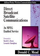
Figure 3.1 is a simplified schematic/block diagram of the DBS communication system. There is a separate identical system for each transponder. Starting at the left of Figure 3.1, source materials from a variety of sources are delivered to the uplink facility, including analog satellite backhaul, cable, fiber, and packaged goods (analog or digital).
Figure 3.1 Overall DBS Communication System (for each transponder)
The incoming source materials are input to video and audio compressors. The outputs of the video and audio compressors are Packetized Elementary Streams (PES), which are input to the multiplexer. A number of separate services are Time Division Multiplexed (TDM) into a single bitstream for each transponder. Chapter 7 discusses the formation, multiplexing, and transport of PESs in detail.
As shown in Figure 3.1, other data can be multiplexed into the bitstream for each transponder. Program Guide information and Conditional Access entitlement messages are the most important sources in this category, but other functions, such as e-mail messages, also can be included.
The Forward Error Correction (FEC) then is applied to the bitstream from the multiplexer. As discussed in detail in Chapter 5, a Reed-Solomon block code is applied first, followed by interleaving and a convolutional code.
The final bitstream (information bits and FEC parity bits, sometimes called the chip stream) is input to the Quaternary (Quadrature) Phase Shift Keying (QPSK) modulator. In a digital communication system, digital modulation usually is employed, which means one of a finite set of waveforms is transmitted in a basic interval called the symbol time. In QPSK there are four possible waveforms, each of which represents two bits. This method is discussed in more detail in Chapter 4 and Appendix B.
The chip stream then is converted to the appropriate frequency for that transponder (between 17.3 and 17.8 GHz), amplified, and transmitted to a DBS satellite.
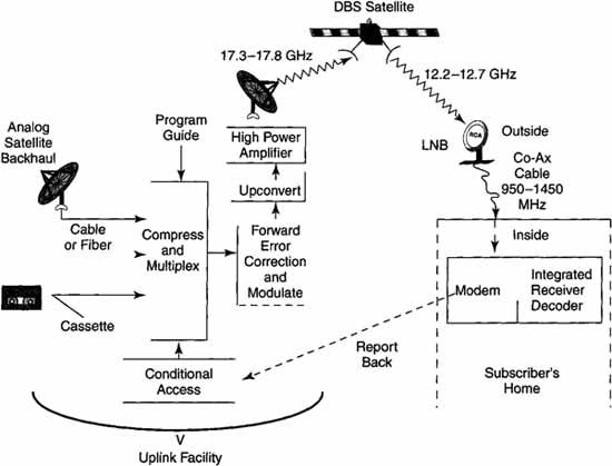
The DBS satellite “transponds” the signal and retransmits it to earth. Figure 3.2 shows that the transponder function consists of converting the uplink frequency to an output, or downlink, frequency (it also provides amplification) that is 5.1 GHz lower. Because the role of the DBS satellite is to translate the signal to a different frequency and then amplify it, the satellite is frequently referred to as a ‘bent pipe.’ It should be noted that, consequently, the signal is not regenerated in the satellite. Conceptually, this transponding can be performed by the heterodyne circuit shown in Figure 3.2.
Figure 3.2 Satellite Transponder Functional Diagram
The 12.2-12.7-GHz signal is received via an 18-inch reflector antenna and offset Low-Noise Block (LNB). The LNB translates the received signal to L-Band (950-1,450 MHz) and amplifies it to drive the coaxial cable to the Integrated Receiver Decoder (IRD). More than 500 feet of coaxial cable can be run from the LNB to the IRD without further amplification.
The IRD (see Chapter 11) basically reverses the uplink process and consists of the following:
Tuner—selects one of the 32 transponders
Demodulator—selects which of the four possible subcarrier waveforms was transmitted, putting out two bits per symbol
Forward error correction decode—removes the concatenated FEC
Demultiplexer—extracts the selected service from the overall TDM bit-stream
Buffer—small storage of demultiplexed bytes between demultiplexer and decompression engines
Decompression engines—decompressors for audio and video
A key feature of Hughes Electronics’ Digital Satellite System (DSS™) is that the uplink can individually request an IRD to initiate a telephone call back to the management center. This feature allows the viewing-history storage to be transmitted to the management center for billing purposes. Note that this allows true impulse pay-per-view operation. The subscriber just selects the service to watch. The viewing-history memory remembers this information and sends it to the management center when it is required.
3.2 Multiple Access and Multiplexing
Most studies have shown that to be economical, a DBS service in the United States must offer between 150 and 200 independent A/V channels. As pointed out in Chapter 1, each orbital slot for DBS has 32 transponders, each with 24 MHz of bandwidth; thus, between five and seven channels have to be allocated per transponder.
Two techniques exist for performing this allocation:
Frequency division multiplexing (FDM)—Each of the independent channels to be shared within a transponder can be assigned a specific frequency within the bandwidth of that transponder. Each of the services then shares the carrier power of that particular transponder.
Time division multiplexing (TDM)—An alternative to FDM is to have time slots for each of the services and to separate the services by allocating different time slots to them.
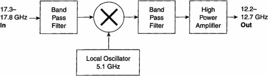
Each technique has advantages and disadvantages. FDM has the advantage that multiple uplinks can be employed with minimal coordination. However, FDM suffers from the basic physics of the satellite transmitter. The high-power amplifier has either a traveling wave tube amplifier (TWT-A) or a solid-state amplifier, both having the so-called s-curve when power out versus power in is plotted.
As shown in Figure 3.3, the sum of the different carriers in an FDM system must operate within the near-linear region of the s-curve. Thus, the FDM system has to have what is called backoff, whereby the power is backed off so that the operation is assured in the linear portion of the s-curve. Typical backoffs as high as 10 dB have been reported; thus, FDM suffers a major drawback compared to TDM.
Figure 3.3 S-Curve for High-power Amplifier
On the other hand, TDM requires that virtually all of the source signals be uplinked from a single location (at least for each transponder). The problem with multiple uplink sites in TDM is the fact that each uplink would have to time its transmission so that it arrived at the satellite at exactly the right time slot. While this can be done with appropriate use of guard bands and beacons back from the satellite, it creates a less-efficient use of the available bandwidth and potentially complicates the receiver, neither of which can be tolerated in a DBS system.
For these reasons, all of the known DBS systems employ time division multiplexing with a single uplink facility. While the uplinks could be separated by transponder with no negative effects, the DBS providers elected to have all of their transponder uplinks at the same location because of the infrastructure required to support the uplinking process. Chapter 10 describes a typical uplink facility.
3.3 Transponder Power and Configuration
The Hughes DBS satellites can be configured as either 16 transponders at 120 watts each (16/120) TWT amplifiers (TWT-A) or as 8 transponders at 240 watts each (8/240). With the three-DBS-satellite configuration of the Hughes DBS satellites at 101° W longitude, the odd transponders are 240 watts per 6/7 rate convolutional code and the even transponders are 120 watts per 2/3 rate convolutional code.
3.4 The Throughput
As covered in Chapter 2, the analog transponder bandwidth is 24 MHz. Section 4.3 of Chapter 4 will show that QPSK is used for all known DBS systems, which yields 2 bits per symbol.
Experience has shown that 20 megasymbols per second can be transmitted through the 24-MHz analog bandwidth. Thus, we have
20 megasymbols per sec * 2 bits/symbol = 40 megabits/sec
In the case of DIRECTV, the Reed-Solomon outer code is (146, 130),1 and there is one sync byte. The effective code rate for the outer code is thus 130/147. This Reed-Solomon code can correct up to 8 byte errors in each 147-byte packet.
1 The (146,130) Reed-Solomon code is really a shortened Reed-Solomon code (see Chapter 5).
DVB utilizes the MPEG 2 Systems packet structure, which is 188 bytes in length. It then utilizes a shortened (204,188) Reed-Solomon code. The inner code can be selected from five different values: ⅓, 2/3, 3/4, 5/6, and 7/8. The overall code rate can be selected from 188/204 times any of the five inner-code rates.
For DIRECTV the inner convolutional code can take on two values: 2/3 or 6/7, depending on the transponder power. Thus, the overall code rate is
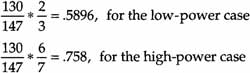
The corresponding information throughputs are 40 Mbps * 0.5896 = 23.58 Mbps for the low-power case, or 40 Mbps * 0.758 = 30.3 Mbps for the high-power case.
3.5 Overall Throughput
As of this writing, there are three DBS satellites at 101° W longitude. Two are configured as 8/240 and one is configured as 16/120. Thus, the throughput is
16 transponders * 30.3 Mbps/transponder = 484.8 Mbps
+ 16 transponders * 23.58 Mbps/transponder = 377.28 Mbps
Total = 862.08 Mbps
The 101° W longitude slot can accommodate a fourth satellite, at which time all four of the satellites would be configured as 8/240. At this point, the total throughput would be
![]()
Thus, the Hughes DBS satellites alone will be raining down on CONUS almost one gigabit per second (Gbps).
Since the compression ratio is between 40:1 and 60:1, the backhaul problem is obvious: between 40 Gbps and 60 Gbps must be input to the system every second of every day.
Now we can answer another question about the services that can be provided from a single DBS orbital slot. If an average service requires 4 Mbps, 213 services (channels) can be provided by DIRECTV and USSB now, with the total rising to 242 if a fourth satellite is launched.
3.6 More Services per Orbital Slot
As explained in Chapter 2, the full CONUS orbital slots are extremely valuable. Therefore, there is continuous pressure to increase the number of services that can be provided. Certainly such possibilities as packing the satellites closer together or utilizing satellites with higher frequencies (Ka for example) will enable continuing expansion. Such solutions will not be available in the near future and are currently very expensive, however. The near-term techniques being used to increase the number of services are statistical multiplexing and, ultimately, symbolic compression (MPEG 4).
Statistical Multiplexing (Stat Mux) takes advantage of the fact that the services that are time-division-multiplexed together into a single transponder are statistically independent. Thus, their bursts will happen at different times so that we can allocate bits to each service according to need. Stat Mux will be discussed in more detail in Chapter 10.
Symbolic compression permits the compression of each part of a service according to the service content. Chapter 13 discusses this in detail.
There are certain techniques in Near Video on Demand (NVOD) that can increase the apparent capacity of the system. These involve making the time between service starts smaller while actually reducing the bit rate requirements. These techniques generally require more memory in the IRD. Such techniques will be discussed in Chapter 11.
3.7 Link Analysis

Since a DBS system can make the uplink very powerful, it has a very small effect on the carrier-to-noise ratio. Thus, the downlink carrier-to-noise ratio can be made to depend only on the downlink parameters.
The basic link equation is

Equation (3.1) can be simplified by inserting known and fixed values.
First, dd can be calculated from the geometry as
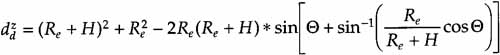
where
θ = elevation angle of IRD receiver
Re = radius of earth = 6,378 km
H = geostationary orbital height = 37,200 km
![]() Re + H = 43,580km
Re + H = 43,580km
Let
![]()
Continuing with the other parts of Equation (3.3a),
![]()
Throughout the continental United States, the elevation angle varies from 27° to 54°. For the minimum elevation angle,
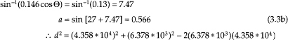
where a is defined in (3.3a).
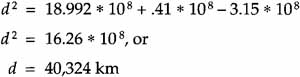
d2 = 18.992 * 108 + 40.679 * 106 – 55.6 * 107 * a
Using the value for a from Equation (3.3),
At the maximum elevation angle,

The entity ![]() from Equation (3.2) then can be calculated (using fd = 12.45 x 10⁹ as the average downlink frequency)
from Equation (3.2) then can be calculated (using fd = 12.45 x 10⁹ as the average downlink frequency)
![]()
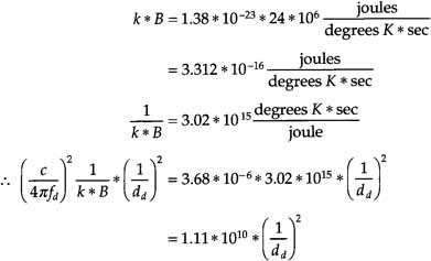
For the minimum elevation angle, dd = 4.0324 * 107 meters, so (l/dd)2 = 6.15 * 10-16, and Equation (3.6) becomes 6.83 * 10-6. For the maximum elevation, dd = 3.8275 * 107 meters, so (l/dd)2 = 6.826 * 10-16 and (3.6) becomes 7.58 * 10-6.
For the minimum elevation angle,
![]()
and for the maximum elevation angle,
![]()
Equation (3.7) will always give the lower result, and (3.7) and (3.8) will be very close in any event, so we will continue the calculation only for Equation (3.7).
For the DBS satellites, EIRP is 53 dBW to 56 dBW, so

or

where η is a combination of losses, η = η1η2η3η4η5η6. When typical values are used, η ![]() .5.
.5.
Since the U.S. DBS systems use an 18-inch (0.45-meter) diameter dish,
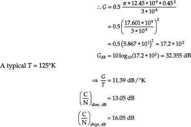
It will be shown in Chapter 5 that the threshold C/N is about 5 dB2 for the low-power case. Thus, there is a margin of more than 8 dB. This might seem to be a rather substantial overdesign, except for the fact that the DBS systems, located in Ku-Band, must deal with rain attenuation.
2 The requirement is really on Eb/No , but for the low-power case, C/N and Eb/No are almost identical.
3.8 Degradation Because of Rain
Above 10 GHz, electromagnetic waves are attenuated by rain. Rain impairs performance in three ways:
1. Attenuation of the desired signal
2. Increase in sky noise temperature
3. Interference from depolarization of an opposite polarization transponder if frequencies are reused as in DBS
Each of these effects must be evaluated separately and the overall effect on carrier-to-noise ratio evaluated. Because of the complexity, these calculations are contained in Appendix A.
3.9 Energy Dispersal
If the transport packets have long runs of Is or Os, it becomes difficult or impossible to synchronize the receiver with the incoming bitstream. Thus, there is a step in the processing chain that disperses energy, to ensure that there are no long strings of the same bit type.
This operation is performed on the transport stream before any subsequent processing (FEC, modulation, and so on). In the receiver, the output of the outer (Reed-Solomon) decoder is the input to an energy-dispersal inverse, which then delivers transport packets to the downstream parts of the receiver.
Figure 3.4 shows the circuit that is used in the DVB Standard for energy dispersal. The generator polynomial for the Pseudo Random Binary Sequence (PRBS) is
Figure 3.4 Energy Dispersal Circuit for DVB

g(x) = 1 + X14 + X15
as can be seen in Figure 3.4.
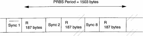
Note that the first byte is the logical complement of the MPEG 2 Systems sync byte. In other words, the MPEG 2 Systems sync byte is 47 hex. The one’s complement of this is B8 hex. This is transmitted before the PRBS is started. The PRBS then runs for the next 187 bytes of the first packet and the next seven packets for a total of 1,503 bytes. Figure 3.5 shows this framing structure.
Figure 3.5 Energy Dispersal Framing for DVB
Note that the circuit in Figure 3.4 is symmetric. In the transmitter, the data input is from the TDM multiplexer. In the receiver, the data is from the Reed-Solomon decoder.
References
[ETSI95] ETSI, ‘Digital Video Broadcast-Satellite,’ European Technical Standards Institute Standard ETSI 300-421,1995.
[Ha90] Ha, Tri, Digital Satellite Communication, New York: McGraw-Hill, 1990.
[Ippolito86] Ippolito, Louis, Radiowave Propagation in Satellite Communication, New York: Van Nostrand Reinhold, 1986.
[Roddy95] Roddy, Dennis, Satellite Communications, 2nd ed., New York: McGraw-Hill, 1995.