Chapter Ten DBS Uplink Facilities
The DBS uplink was introduced in Chapter 3. In this chapter, the components of the uplink facility are discussed in more detail.
The DBS uplink facilities are very complicated electronic systems. The broadcast facilities for a transponder are roughly equivalent to those of a television station. Since the typical uplink facility provides for 20 to 30 transponders, it has the complexity of more than 20 television stations. What’s more, the uplink must continuously provide for 200 television channels. Each of these must be compressed and time-division multiplexed (TDM) into bit-streams for transmission to the satellite transponders.
Another way to view the complexity of a DBS uplink facility is to examine the bit rates involved. When a DBS orbital slot is fully populated, 32 transponders will be operating at 30.3 Mbps (information bit rate) for a total of 970 Mbps. Since the compression ratios are 40-60:1, 40 to 60 gigabits per second (or the equivalent) must be fed into the system every second of every day.
10.1 Existing Uplink Facilities
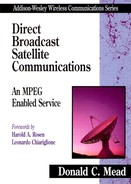
As of December 1996, there were four operating uplink facilities, as shown in Table 10.1. Figure 10.1 is a photograph of the DIRECTV uplink facility at Castle Rock, Colorado.
Table 10.1 Operating Uplink Facilities
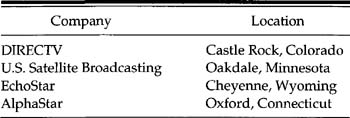
Figure 10.1 Castle Rock, Colorado, Uplink Facility, From Jim C. Williams, ‘Airborne Satellite Television,’ Avion, Fourth Quarter:44, 1994, Used with permission.
Organization of uplink facilities by transponder (or group of transponders) would solve the TDM versus FDM issue; that is, the system would be FDM by transponder and TDM within a transponder. However, the investment in common features, such as broadcast automation, plus the issues of synchronizing a common program guide and so on, have led all the companies listed in Table 10.1 to have a single uplink facility for all their transponders.
10.2 Constituents of an Uplink Facility
The following information is excerpted from a paper presented at the 30th SMPTE Conference in February 1996 [Echeita96]. The equipment in an uplink facility includes:
• A fully automated Sony broadcast system for 200 video and audio channels
• A 512-by-512 output Sony digital routing system that carries four audio signals for each video signal
• Fifty-six Sony Flexicart robotic videotape playback systems
• Two 1,000-cassette Sony Library management systems
• More than 300 Sony Digital Betacam videotape machines
• State-of-the-art scheduling hardware and software
• Fifty-six Multichannel Compression Systems (see next section)
• Four 13-meter transmitting antennas plus multiple receive antennas
The uplink facility includes, among other things, the following:
• Three 1.5-megawatt generators
• An Uninterruptible Power System (UPS)
• A 100,000-gallon fire-suppression system
• Computerized environmental monitoring and control
10.3 Key Uplink Subsystems
Much has been written about uplink facilities and equipment. The two subsystems of particular interest for digital communications are the compressor/multiplexer and the QPSK modulator.
10.3.1 Compressor/Multiplexer
Several companies develop and manufacture uplink equipment, including Compression Laboratories Inc. (CLI), a division of General Instrument (GI), and DiviCom. The following discussion emphasizes the CLI/GI system called the Magnitude™ [CLI96] solely because the author is more familiar with it.
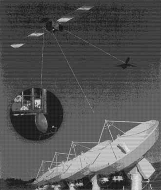
Figure 10.2 is a block diagram of a compression/multiplexer system. The multiplexer block contains the common elements, including the mounting rack, power supplies, and so forth. The blocks marked video compressors accept the incoming video formats (S-Video or D-l are preferred) and compress the service according to MPEG 2 MP@ML as described in Chapter 8. There is no theoretical limit to the number of such video compressors in a single multiplex, although 6 to 8 is a practical range.
Figure 10.2 Compressor-Multiplexer Block Diagram
The audio encoders accept digital audio in the form of 48 Ksamples per second, 16 bits per sample, and compress it according to MPEG 1 (ISO 11172-3) Layer II at 192 Kbps (Chapter 9). The encoders offer a range of bit rates but 192 Kbps is used by all known DBS systems.
User data also can be an input to the multiplexer in compliance with MPEG 2 Systems (ISO 13818-1,1994), as discussed in Chapter 7. Data may come in many forms. In Chapter 6, it was shown that the delivery of ECMs and EMMs, along with other authentication and signature data, must be transmitted as User Data. Similarly, Electronic Program Guide data must be sent as other data.
One interesting use of User Data involves audio services. When MPEG 2 Audio (ISO 13818-3) established its six-channel audio, it did so in a backward-compatible way. This means that an MPEG 1-compliant decoder can derive a stereo audio from an MPEG 2 audio bitstream. This is accomplished by coding the left front and right front audio inputs as the left and right inputs from MPEG 1. The center, right surround, left surround, and subwoofer channels are compressed and sent as User Data.
An MPEG 1 audio decoder decodes the left and right signals to create normal stereo. A more sophisticated receiver can use the User Data plus the audio data to create a six-channel sound for a home theater. Note that such an implementation can be done without making an installed base obsolete. It is only an encoder change.
The Conditional Access input provides encryption keys for the Multiplexer, which applies them to the service streams as well as to other data that will be used by IRDs for accessing services.
The Electronic Program Guide is provided by another PC that provides its information as User Data with a specific PID (see Chapter 7). The current time resolution of Electronic Program Guides is 30 minutes, although this probably will decrease in the future.
The System Executive PC performs a number of functions, including overall supervision of the system. Through it, various services are assigned PIDs. It also manages the statistical multiplexing and system clock distribution.
10.3.2 The Modulator
To call this unit a modulator is a serious understatement. Both of the systems with which I am familiar use Comstream modulators: CM2000 for DSS waveform systems and CM3000 for DVB systems. The CM2000 is discussed in this section.
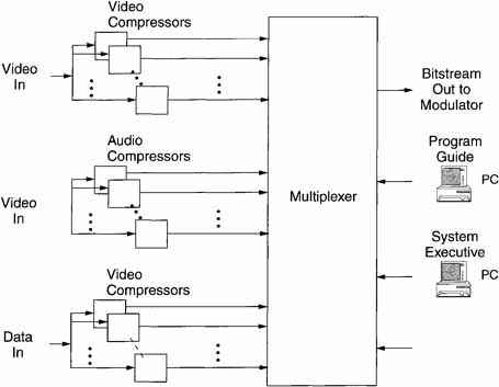
The functions of the Reed-Solomon Coder/Interleaver/Convolutional Coder were covered in Chapter 5. Energy dispersal, raised cosine filter, and QPSK modulator were discussed in Chapter 3. Figure 10.3 is a simplified diagram of the modulator that shows how all these functions come together. They will not be dealt with further here. Instead, the role of the frequency synthesizer and its interaction with the multiplexer will be explained.
Figure 10.3 Modulator Block Diagram

For DIRECTV, the frequency synthesizer puts out a frequency 2/3 (40) = 26.67 Mbps or 6/7 (40) = 34.29 Mbps, depending on which code rate is being employed. DVB outputs comparable bit rates for its code rates. This clock is used by the multiplexer to clock out the serial bitstream. If an external 10-MHz clock is present, the frequency synthesizer will lock to this reference (to the nearest integer symbol).
For DIRECTV, the compressor/multiplexer organizes the data into packets of 1,176 bits each (147 * 8). These consist of 1,040 bits of information, 128 bits of stuffed zeros where the Reed-Solomon parity bits will be added, and 8 bits of stuffed zeros where a sync word will be added. The sequence of 1,176 bits repeats every 44.1 seconds for the low-rate code and every 34.3 seconds for the high-rate code.
The modulator receives the 1,176 bits, inserts 128 Reed-Solomon parity bits in place of the stuffed zeros, and adds an 8-bit sync word. It then adds the convolutional code bits (at a code rate of 2/3 or 6/7) and outputs the constant 40-Mbps serial bitstream to the QPSK modulator. Note that the 40-Mbps rate is constant regardless of code rate. Because the QPSK modulator codes two bits per symbol, the symbol rate is 20 mega symbols per second.
10.4 Statistical Multiplexing
All known DBS systems use time-division multiplexing within a transponder. Further, natural video is very bursty in nature. In compressing CCIR 601-1 video, MPEG 2 can require as low as 1 Mbps and as high as 10 Mbps to create good-quality encoded video.
Thus, a dilemma exists. If the bit rate for a service is set at the minimum required to give good quality, say 10 Mbps, this will be very wasteful because this rate will be required only a small fraction of the time. On the other hand, if a low rate is set, there will be times when the quality is too low.
The solution to this dilemma is called statistical multiplexing. Recall from Chapter 8 that MPEG 2 video compressors have a rate-control mechanism.
Essentially, this consists of controlling the quantization levels within certain limits so that the buffers stay within certain limits.
If this control (for all services within a multiplexer) is given to the multiplexer, it can allocate bits to each service according to its requirements. Thus, the individual compressors become variable bit rate, constant quality.
What happens if all (or a large number) of the services within a multiplex all burst up simultaneously? This will happen, although infrequently. In this case, all the services will have to suffer some temporary quality degradation. This usually will be of such short duration that the average viewer will not even notice.
Statistical multiplexing is an active area of research, and advancements are still being made.
References
[Bursky96] Bursky, Dave, Full Feature MPEG 2 Encoder Needs Just Five Logic ICs, Electronic Design, April 1996.
[CITEL94] CITEL Inter-American Telecommunication Commission, Final Report, First Meeting of Permanent Consultative Committee II: Radiobroadcasting (PCC.II), August 1994.
[CLI96] Magnitude Technical White Paper, Compression Laboratories Inc., Internet Document, 1996.
[Echeita96] Echeita, Richard J., Challenges in a Digital, Server-Based Broadcasting Environment. In Proceedings of the 30th SMPTE Advanced Motion Imaging Conference (Session 5), February 1996.
[Williams94] Williams, Jim C, Technologies for Direct Broadcast to Airliners, AVION (Fourth Quarter), 1994.