Chapter Six. Conditional Access
The providers of program materials and the distributor of the programs (the DBS operator) understandably want to be paid for their intellectual property and services. To ensure that the broadcast of program materials can be viewed only by those who are authorized for such viewing (and who have agreed to pay for such services), conditional access (CA) systems have been developed. As the name implies, access to the materials is conditional, based on the viewers being authorized to view them.
6.1 Objectives of a CA System for DBS
A DBS CA system should be able to provide the following:
1. Access control
2. Copy control (antitaping)
3. Regional control (regional blackout)
4. User control (parental lockout)
5. Addressing capabilities to handle 100 million subscribers
Part of the CA system should permit a backlink from the subscriber to the management center so that a viewing history can be retrieved from the Integrated Receiver Decoder (IRD), thus permitting impulse pay-per-view. This link should provide a digital signature or authentication that the correct IRD is responding.
The CA system also must be capable of recovering from security compromise.
6.2 Types of Attackers
In the popular media, those who try to breach CA systems in an effort to view the materials for free are called pirates. Those who succeed are actually thieves, but in this book they will be called attackers.
There are two basic types of attackers: the graduate student who attacks the CA system because of the challenge and the commercial attacker who hopes to sell illegal access. The first, or ‘lone-wolf’ variety, poses little threat because there are so few of them (fewer than 1 or 2 percent of those involved). The commercial attacker is another story.
Make no mistake—piracy is potentially a big business. To illustrate, suppose a DBS provider has 10 million users, but 10 percent of them, or one million, are provided access by an attacker. If the average subscriber pays $40 per month, or $480 per year, the loss to the DBS provider is $480 million per year! Even if the attacker charges only half that of the legitimate provider, his revenues for the year are still $240 million, almost all of which is pure profit. It is not surprising that serious attacks are made on the DBS CA system and that DBS operators make a major effort to defeat the attackers.
6.3 Some Encryption Preliminaries
Because all DBS systems involve the transmission of digital bit streams, the corresponding CA systems are best implemented by encryption/decryption technology (as opposed to scrambling, and so on). Thus, DBS systems can take advantage of the huge effort that has gone into the cryptography field.
The creation and breaking of codes is probably as old as human history. For a fascinating review of this history, see David Kahn’s book, The Code-breakers [Kahn67].
All modern encryption algorithms employ a key, denoted by k. Using E to denote encryption, D to denote decryption, P to denote the plaintext message to be sent, and C for the coded message, we can write
![]()
![]()
In words, the coded or cipher message C is created by encrypting the plaingtext message P with the key k. The plaintext message P is recovered from C by decrypting it with the same key k.
6.4 Mathematical Preliminaries
The following sections require an understanding of modulo arithmetic. The basic notation is
![]()
where k is an integer,
k = 0,1,2,3, …,
and * denotes multiplication.
Another way of saying this is that a is the remainder after b is divided by n. It is easy to show the following modulo arithmetic operations:
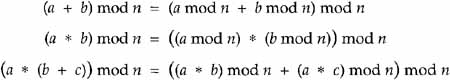
Powers in modulo arithmetic are just extensions of multiplication.
The most important property of modulo arithmetic used in the following sections is that
![]()
For example, let b = 7, n = 5, and y = 4. Working on the left side of (6.5),
[b mod n] y mod n = [7mod5]4 mod 5 = 24 mod 5 = 1
The right-hand side is
74 mod 5 = 2401 mod 5 = 1
In modulo arithmetic, division is defined as a multiplicative inverse. That is, if (a * c) mod n = 1, then c is the multiplicative inverse of a and is written c = a-l. As opposed to finding multiplicative inverses with real or rational numbers, multiplicative inverses in modulo arithmetic may not exist.
Even when multiplicative inverses exist, they are not easy to calculate. It is interesting that an extension of an algorithm attributed to Euclid in 300 BC (although it may be several hundred years older) can be used to find modulo multiplicative inverses.
6.4.1 The Euclidean Algorithm
The Euclidean Algorithm finds the greatest common divisor of two numbers, say r0 and r1, noted gcd (r0, r1), where r0 > rl. The Euclidean Algorithm then forms

Then, gcd (r0, r1) = rm.
It can be shown that an element has a multiplicative inverse modulo r0 if and only if gcd (r0, r1) = 1. Thus, in Euclid’s Algorithm, r1 has a multiplicative inverse if and only if rm = 1.
Euclid’s Algorithm shows whether an inverse exists but does not calculate the inverse. The following Extended Euclid’s Algorithm [Stinson95] actually calculates the inverse.
6.4.2 Extended Euclid’s Algorithm
Define a sequence of numbers t0, t1, … tm according to the following recursion:

where the qj are defined above. Then it can be shown for 0 ≤ j ≤ m, that rj = tjr1 mod r0. If gcd (r0, r1) then tm = r1-1 mod r0. This can be put into the following algorithmic form:
1. n0 = n
2. b0 = b
3. t0 = 0
5. ![]()
6. r = n0 – q * b0
7. While r > 0, do
8. temp = t0 – q * t
9. If temp = 0, then temp = temp mod n
10. If temp ≤ 0, then temp = n – ((-temp)mod n)
11. t0 = t
12. t = temp
13. n0 = b0
14. b0 = r
15. ![]()
16. r = n0 – q * b0
17. If b0 ![]() p1, then b has no inverse mod n.
p1, then b has no inverse mod n.
Else, b-1 = t mod n.
Example Calculate 28-1 mod 75
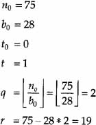
Start recursion:
| 1. | 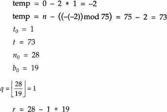 |
| 2. |  |
| 3. | 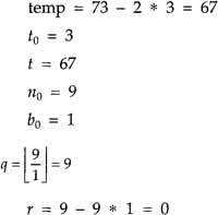 |
Since r = 0, the recursion terminates. Since b0 = 1, an inverse exists and t is that inverse. Thus, 28-1 mod 75 = 67. For the doubters, calculate 26 * 67 = 1876, 1876/75 = 25 with r = 1.
6.5 Cryptographic Algorithms
A DBS/CA system will typically use four or five different cryptographic techniques to perform the various required functions. A symmetric key technique, such as the Data Encryption Standard (DES) discussed in the following section, can provide high-speed encryption that can be used to encrypt the individual services. However, the key distribution can be a problem. A public key system such as RSA solves the key-distribution problem but is too slow to encrypt services. Digital Signature algorithms can prove that the source of a communication is valid, and message authentication codes (MAC) can be used to ensure that a message has not been tampered with.
In this section the key algorithms are described. Section 6.7 presents a generic CA system that employs these algorithms.
6.5.1 The Data Encryption Standard
DES is a U.S. national encryption standard based on original input from IBM. The National Security Agency (NSA) consulted with the National Bureau of Standards (NBS), now the National Institute of Standards and Technology (NIST), on the development of the standard.
In considering cryptographic algorithms for DBS/CA, there are three criteria:
1. The algorithm must not cause an expansion of the data.
2. The algorithm must be capable of very fast operation.
3. The decryption must be capable of implementation in very inexpensive hardware.
The DES algorithm satisfies all of these criteria.
DES is a block cipher. It takes in 64 bits, encrypts the 64 bits with a 56-bit key, and outputs 64 bits of cipher text. Thus, we see that the first criterion is met; the cipher text length is exactly the same as the plaintext length (zero overhead).
Note: The ciphertext length can never be less than the plaintext because the plaintext could never be recreated. It is a basic theorem of linear algebra that an n-to-less-than-M mapping cannot be inverted.
The DES algorithm puts the 64 bits of input through 16 identical iterating rounds of processing. The processing is shown in Figures 6.1 and 6.2.1
1 Figures 6.1 and 6.2 and Tables 6.1 through 6.5 were adapted from B. Schneier, Applied Cryptography [Schneier94], as has been documented in the applicable U.S. standard.

Referring to Figure 6.2, the 56-bit key is divided into two 28-bit halves. The halves are shifted left one or two bits, depending on the round. Table 6.1 shows the number of shifts per round. After being shifted, 48 of the 56 bits are selected according to Table 6.2. This is called the compression permutation.
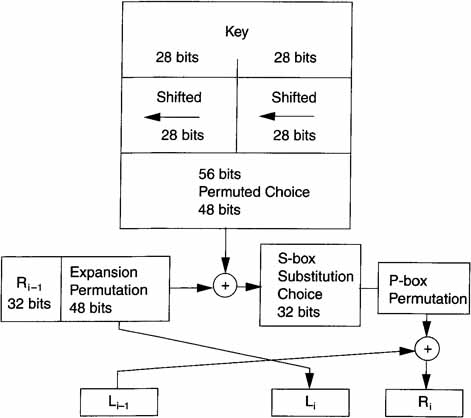
Table 6.1 Key Shifts per Round
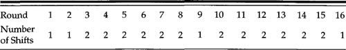
Table 6.2 Compression Permutation

Referring to Figure 6.2, the 32 bits of the right half of the data are expanded to 48 bits in an expansion permutation. The mapping is shown in Table 6.3.
Table 6.3 Expansion Permutation

Much of DES’s design revolves around reaching—as quickly as possible—the condition of having every bit of the cipher text depend on every bit of the plaintext and every bit of the key. The expansion permutation contributes to this.
After the compressed key is exclusive ORed with the expanded block, the 48-bit result moves to a substitution operation. The substitution is performed by eight substitution boxes or S-boxes.
The 48 bits are divided into eight blocks of six bits each. Each of the blocks is associated with one of the S-box tables. Each table consists of four rows and 16 columns. Table 6.4 shows all eight boxes.

If the six bits in a block are labeled b1, b2, b3, b4, b5, and b6, then b1 and b6 form a two-bit row address. The four bits b2, b3, b4, and b5 form a four-bit column address. The output is the corresponding four-bit entry from the S-box. The eight four-bit entries from the S-box outputs are concatenated to form a new 32-bit output.
The 32-bit output of the S-boxes becomes the input to the permutation or P-box. Table 6.5 shows the one-for-one permutations of the P-box. Before the first round and after the sixteenth round, there is an initial permutation and a final permutation. Since these do not add to the cryptographic security of the algorithm, they are not discussed here.
One of the remarkable aspects of the DES algorithm is that the same algorithm works for decrypting and encrypting if the order of the keys used for each round is reversed.

6.5.2 Public Key Cryptography
For an economically viable DBS service, a number of different services must be offered. Each service costs extra and requires a different encryption key. Further, it is desirable to frequently change the keys for each service.
Public Key Cryptography provides a means for delivering these keys to the subscriber. In public key cryptograph there are two keys: the public key and the private key. Neither can be calculated from the other.
Suppose the conditional access center has a database of the public key associated with each subscriber’s IRD. Suppose further that there are two very large integers, n and g, with n > g. Both n and g can be publicly known without compromising security. Suppose x is the subscriber’s public key and y is the subscriber’s private key, which is embedded in the IRD.
The CA center forms X = gx mod n, and transmits it through the satellite to the subscriber’s IRD. The IRD calculates k = Xy mod n, or
![]()
Using Equation (6.5), this reduces to
![]()
Thus, even though an attacker knows g, n, and X, he still cannot determine k.
A practical public key algorithm for the distribution of DES keys is the RSA algorithm, named for its three inventors: Ronald Rivest, Adi Shamir, and Leonard Adelman.
Choose two large prime numbers, p and q (which must remain secret), and compute
![]()
Then randomly choose the public key e such that e and (p – 1)*(q – l)are relatively prime. Compute the private key d = e-1 mod ((p – 1) * (q – 1)).
The encryption formulas are then
![]()
which is transmitted. To decode,
![]()
This can be derived by the following:
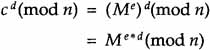
from Equation (6.5).
Now, e * d = k * (p – l) * (q-l) + 1 from the definition of modulo arithmetic and Equation (6.5).
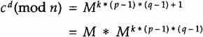
However, since Mk(p-1)(q-1) = l,cd (mod n) = M.
Note that we can continue to send messages to the IRD as fast as the RSA algorithm can decode them. These messages may be the DES keys or other instructions, such as ‘call in on the modem.’
6.5.3 One-Way Hash Functions
In many cases, particularly when dealing with long messages, it is important to determine whether the messages are authentic without dealing with the messages themselves. These functions generally are compactions of the messages. They have many names, including message digest and message authentication.
A one-way hash function H(M) operates on an arbitrary-length message M and produces a fixed-length hash value h of fixed-length n. One-way hash functions have the following properties:
• Given M, it is easy to compute h.
• Given h, it is hard to compute M.
Note that because h is a many-to-one mapping, in general more than one M can create h. Given M, it is hard to find another message M’ such that H(M’) = H(M), even though we know they exist.
Most one-way hash functions are designed to take in two n-length inputs and produce a single n-length output. Usually, the inputs are a block of text, and the hash of the previous block of text, that is,
hi = f(Mi,hi-l)
The hash of the last block is the hash for the entire message.
Professor Ronald Rivest (of RSA fame) has developed one-way hash functions called MD4 and MD5 (as in Message Digest), both of which produce 128-bit hash outputs. MD5 is proposed in the generic CA system discussed in section 6.7. However, the Secure Hash Standard, which is the United States national standard, has 160-bit hash outputs and, thus, is cryptographically stronger at the cost of more processing.
The reader interested in more information on one-way hash functions is referred to Schneier’s excellent book [Schneier94], which is not only readable, but has an excellent bibliography of original source materials.
6.5.4 Digital Signatures
In certain electronic communication situations, it is desirable to have a digital signature, which plays the same role in electronic communication that a written signature plays in written communication. The digital signature of a message is a bit string attached to the message. Digital signatures are almost always implemented with public-key cryptographic techniques.
It is frequently more practical to sign a one-way hash of the message rather than signing the message itself.
Uriel Feige, Amos Fiat, and Adi Shamir (the S of RSA fame) developed an algorithm called a zero-knowledge proof of identity, which is an authentication/digital signature scheme. The basic concept of this scheme is covered by U.S. Patent 4,748,668. It is used in DBS/CA to prove that an inserted smart card is valid.
6.6 Generic CA System
Because information is a valuable tool for information thieves, we must not divulge the details of any specific CA system. What follows is a description of a generic CA system that is a variant of one that was proposed to the Digital Audio Video Council (DAVIC) in May of 1995 by Scientific Atlanta [DAVIC95].
Figure 6.3 shows a simplified block diagram of this generic CA system. At the transmitter, a random DES key is selected. Note that this is not a
Figure 6.3 Generic CA Encoder
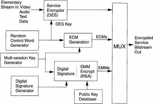
pseudorandom number but, rather, a truly random number that should be derived from a physical process, such as the noise in a diode, and so on. It is used to encrypt the video and audio for a service. The DES key becomes the message for encryption by the multisession key as part of the ECM generation process. The multisession key is signed with a digital signature and then encoded with the public key of an RSA public encryption system. The ECMs and the EMMs are multiplexed together to form the encrypted service bitstream.
Figure 6.4 shows the block diagram for the ECM generation. The DES key is encrypted with the multisession key using triple DES encryption. The multisession key, the DES key, and up to 320 bits of stream description information are combined as the “message” and authenticated by the MD5 message authentication code (MAC). The encrypted DES key, the MAC, and the stream description bits become the ECM.
Figure 6.4 ECM Generator

Figure 6.5 shows triple DES encryption. The plaintext is first DES encrypted with key Kl. It is then inverse DES encrypted with key K2. Finally, it is DES encrypted with key Kl. In the decoder, the process is reversed. The motivation for triple DES is that it effectively increases the key length from 56 bits to 112 bits.
Figure 6.5 Encoding with Triple DES

CA Decoding
1. The encrypted service bitstream is demultiplexed and the EMMs are selected.
2. The EMM is decrypted with the private part of the RSA key.
3. Check the digital signature of the multisession key. If valid, proceed to 4.
4. Select ECM Check ECM MAC. If valid, stream description information is stored in appropriate places in IRD.
5. Use the multisession key to triple DES decrypt the DES key.
6. Use the DES key to decrypt the individual services.
References
[DAVIC95] Paper presented by Scientific Atlanta at the Digital Audio Video Council meeting, Rome, May 1995.
[Kahn67] Kahn, David, The Code Breakers. New York: Macmillan, 1967.
[Schneier94] Schneier, Bruce, Applied Cryptography. New York: John Wiley & Sons, 1994.
[Stinson95] Stinson, Douglas R., Cryptography Theory and Practice. Boca Raton, FL: CRC Press, 1995.