Chapter Eleven. Integrated Receiver Decoder
The key to a successful DBS service is an inexpensive integrated receiver decoder (IRD). After all, if consumers cannot afford the IRD, they cannot subscribe to the DBS service! This was considered so important that the first contract for IRDs required that the retail price be $700 or less.
The inexorable march of Moore’s law, coupled with the learning curve and production volumes in excess of a million units a year, drove the IRD price down to zero (with one service provider’s $200 rebate) as of July 1997.
11.1 IRD Components
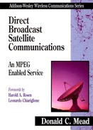
The IRD consists of an outdoor unit (ODU) and an indoor unit (IDU). These two units are connected by a coaxial cable. Figure 11.1 is from a photograph of an ODU, which consists of a reflecting antenna plus an LNB (see section 4.4 in Chapter 4). Note that the LNB is offset from the focus of the parabaloid reflector, thus minimizing the blockage of the incoming signal.
Figure 11.1 IRD Outdoor Unit
Two types of LNBs are commercially available. One has a single coax connector. The center conductor carries the received signal from the IDU back to the LNB in addition to a DC voltage of either 13 volts or 17 volts. Based on which channel is selected, the IDU determines which of the two voltages to put on the cable, which then selects the proper polarization for the channel.
The second type of LNB has two coax connectors. In the simplest case, the dual LNB can service two IDUs. With some additional components, however, the dual LNB can be used to service a large number of IDUs (see section 11.5).
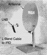
Figure 11.2 is from a photograph of a typical IDU, with its remote control on top. Figure 11.3 is a photograph of a typical remote control. Both the remote control and the IRD are designed to be especially user-friendly.
Figure 11.2 IRD with Remote Controi
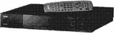
Figure 11.3 Typical Remote Control
11.2 The IRD Architecture
The LNB architecture is shown in section 4.4 , so this section discusses the IDU. Figure 11.4 is a block diagram of the IDU. The L-Band signal from the ODU is the input to the tuner.

The tuner selects one of the 32 transponder signals for further processing. A 5-bit select signal from the microprocessor controller (MC) determines this selection. The tuner is a voltage-controlled oscillator (or a frequency synthesizer) that is called the local oscillator (LO). This is mixed with the incoming L-Band signal to form sum-and-difference frequencies.
The LO frequencies are set so that the difference between the selected transponder center frequency is 12 MHz. Thus, the transponder output occupies the band 0 MHz to 24 MHz and is isolated by a low-pass filter. Another way to view this is that the tuner forms a second heterodyne step: The LNB steps the signal down from Ku-Band to L-Band, and the tuner steps the signal down to low-passed 24 MHz. Of course, the tuner is variable in frequency, so different parts of the L-Band signal can be selected.
The tuner output is input to the demodulator. The QPSK demodulator converts the incoming signal to digital: 2 bits per incoming symbol. The bit-stream from the demodulator becomes the input to the decoders of the concatenated code, shown as FEC-1 in Figure 11.4.
First, the inverse of the Energy Dispersal is performed. Then, the Viterbi decoder decodes the convolutional code (see section 5.6 in Chapter 5). The Viterbi decoder is followed by the deinterleaver. Finally, the Reed-Solomon decoder creates the original information bitstream.
The first generation of IRDs located the tuner, demodulator, and inverse forward-error-correction circuitry on a daughterboard that is connected to the IRD motherboard. The signal flow was byte parallel from the output of the Reed-Solomon decoder to the motherboard.
The information bytes from the FEC-1 function are time-division demultiplexed into individual service byte streams. Note that the selection is one of n, where n is the number of services that have been time-division multiplexed together on the selected transponder. The output of the demultiplexer is stored in buffer memories until it can be used by the appropriate decryptors and decoders, which provide the output for display.
Control of the IDU is provided by the microprocessor controller (MC). It receives user inputs from the front panel or remote control. Based on these inputs, the MC selects the desired channel for decompression (via the tuner and demultiplexer) and provides the conditional access (CA) controller with this information. The CA controller then provides the correct decryption keys for the selected services.
When requested by an over-the-air command, the MC connects to an access telephone number via modem. When this connection is made, the viewing history memory is transmitted to the Management Center. For valid subscribers, new keys are then sent to the IDU for the subsequent period.
Note that by having the viewing history remember the pay-per-view (PPV) services used and then downloading this to the Management Center for billing, true impulse PPV is obtained. All the consumer has to do is watch the desired service. There are no calls to make, no corresponding frequent busy signals, and so forth.
11.3 Electronic Program Guide
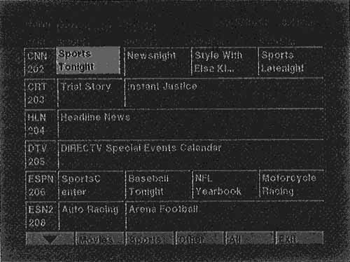
The Electronic Program Guide (EPG) differentiates DBS services from broadcast TV and C-band services, both of which require a separate paper pamphlet as a guide to the services offered. Also, the EPG allows IDU manufacturers to differentiate their services, because the graphical form of the EPG usually is not specified by the service provider.
Figure 11.5 is a screen image of the first-generation RCA-brand IRD Program Guide.1 Note that the format is very similar to a newspaper listing with the service vertical (in increasing numerical order), and the time horizontal. Note that because of the large number of services and limited storage, only programs three hours in advance are shown. Published reports indicate that this is an area in which future improvements will be made.
1 This and all subsequent screen images in this chapter were obtained by connecting the S-Video output into a Macintosh 8500, then using the video viewer to capture the image.
Figure 11.5 Program Guide Screen
11.4 Menu Selections
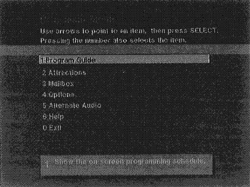
Figure 11.6 is a screen image of the main menu. Item 1 is the Program Guide previously discussed. Each of the menu items that follow permit the selection of other functions. This section is not intended to be a complete listing of all of the possible services. Instead, it illustrates how a modern system can simplify consumer operation.
Figure 11.6 Main Menu
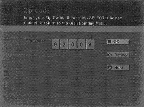
If Options is selected from the main menu shown in Figure 11.6, Figure 11.7 results. The selection of setup results in Figure 11.8. Selecting item 1, Zip Code, results in Figure 11.9. At this point, enter the zip code where the antenna is located. Figure 11.10 shows this done for Carlsbad, California.
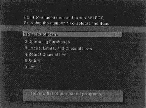
Figure 11.8 Dish Pointing


Figure 11.10 Zip Code Entered for Carlsbad, California
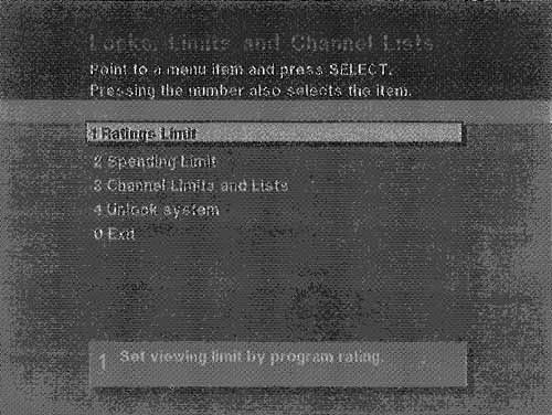
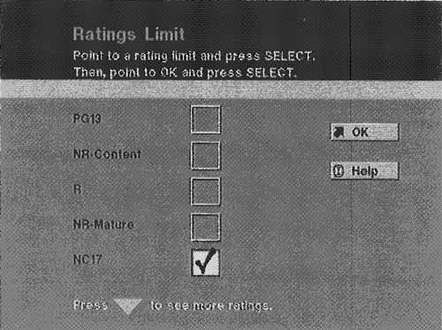
The system responds with the correct elevation and azimuth angles, as shown in Figure 11.11. The antenna has registration marks that indicate the elevation. Thus, with the base of the antenna flat (measure it with a level), set the elevation to the correct angle. Select Signal Meter from the menu (Figure 11.12). Adjust the azimuth angle using an inexpensive compass until the signal meter creates a loud continuous tone. Finally, Figures 11.13 and 11.14 detail some of the control the customer has over content by showing the Locks and Limits menu and the Ratings Limit menu.
Figure 11.11 Elevation and Azimuth Angles for Carlsbad, California
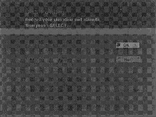
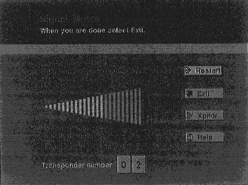
Figure 11.13 Locks and Limits
11.5 Multiple TV Sets
One of the most frequently asked questions in DBS is, I have more than one TV set. How do I get DBS for all of them? First, you have to have a decoder box for each TV set because there is only one decompress system in each of today’s IRDs. Second, you have to use a dual LNB, with one LNB assigned to each of the two polarizations.
The dual LNB has two independent LNBs, one for each of the two polarizations. The first step is to force each of the two LNBs to select one of the polarizations by supplying 13 volts on the center conductor of the coax connection to the LNB and 17 volts to the other. This is done by the dual LNB power-supply injector shown in Figure 11.15. The capacitors shown in each leg keep the DC voltages from getting into the multiswitch shown in Figure 11.16.
Figure 11.15 Dual LNB Power-Supply Injector
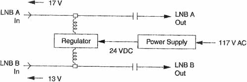
Figure 11.16 Multiswitch
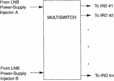
The multiswitch receives the AC component from the LNB injector, ft outputs this signal to the number of IRDs that are connected to it. Common multiswitch configurations are for 2,4,8, and 16 IRDs, The IRDs attach to the multiswitch and provide a 13- or 17-volt signal to the multiswitch, which then provides one of the two polarizations to the IRD. Each IRD operates as if it had the entire antenna and LNB to itself, although they are really sharing them.
References
[Bursky95] Bursky, Dave, Single Chip Performs Both Audio and Video Decoding, Electronic Design, April 1995.
[Goodman96] Goodman, Robert L., Digital Satellite Service. New York: McGraw-Hill, 1996.
[Schweber95] Schweber, Bill, Direct Satellite Broadcast Brings Downlink Directly to Your Set-top Box, EDN, December 1995.