
Appendix E. Cyclical Redundancy Code
In most packetized communication systems, it can be valuable to know if a transmission error has occurred. If a return link is available, a Negative Acknowledge (NAK) can be sent back to the transmitter so the packet can be resent. In broadcast audio/visual services, it is usually possible to conceal errors if it is known that an error has occurred. Thus, both the Systems and Audio parts of MPEG incorporate a Cyclical Redundancy Code (CRC) to detect errors in the bitstream.
In Chapter 5, simple Elias codes were introduced. It was shown that by breaking a message into 4-bit nibbles and calculating row- and column-parity checks that were appended to the message, all single bit errors in the message could be corrected. If only the column-parity bits were calculated and appended to the message, all single bit errors in the message could be detected. The CRC provides this type of error detection and operates in the same way: A set of parity bits is calculated for the message and appended to the message bits. However, as we shall see, the CRC is much more powerful than simple parity checks.
The problem with simple parity checks is that they are based on addition. Each incoming byte affects only one byte in the parity bits. It turns out that a form of division can be used to calculate the CRC, which is much more powerful. It can be shown that the probability of an undetected error for the CRC-32 (32 bits) is 1/232.
The idea behind the CRC is to treat the message as a very large binary number and divide it by another binary number. The quotient is thrown away and the remainder is used as the set of parity bits, sometimes called the checksum. The divisor is usually presented in the form of a polynomial called the generating polynomial. For the 16-bit CRC used for MPEG 1 Audio, the generator polynomial is G(x) = x16 + x15 + x2 + 1. Basically, this means that the divisor has a ‘1’, where the power of x is nonzero and zeroes elsewhere.
The division to form the CRC parity bits is a bit unusual. First, it uses the following binary arithmetic:

Also, when performing the division, if the part of the dividend that is being divided by the divisor for a particular quotient bit starts with a ‘1’, the quotient bit is a ‘1’; if ‘0’, the quotient bit is a ‘0’.
This is illustrated by the following example.
Generator polynomial:
![]()
which can be represented by ‘110101’.
Message: ‘1010001101’. The generating polynomial uses 6 binary positions. One less than this, or 5 zeroes, are appended to the message to form the dividend. The division is then shown in Figure E.1.
Figure E.1 Division to Form CRC
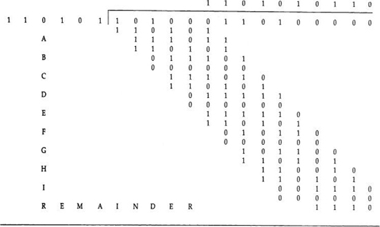
Several items about the figure should be noted. First, the column of capital letters—A through I on the left—will be used later. Next, note the first step. The quotient bit is a ‘1’, even though ‘110101’ is larger than ‘101000’ because ‘101000’ starts with a ‘1’. Finally, the line labeled REMAINDER is the CRC value, ‘1110’. The message transmitted then is ‘10100011011110’—the original message with the 4 CRC bits appended.
In the decoder, the message bits are divided by the same divisor. If the result is ‘1110’, the probability is very high that there have been no errors.
One of the interesting aspects of the CRC is that the division to find the CRC value can be performed by a shift register and Exclusive OR circuits. Consider the circuit of Figure E.2. Note in the figure that the Exclusive OR circuits are associated with the outputs of the fifth stage (the one at the input), the fourth stage, and the second. These are the powers of x in the generating polynomial that are nonzero. The stages are flip-flops or delay elements. Table E.1 shows the process as the input message (shown in the right column) is shifted into the shift register. The register starts with all zeroes. The output of each stage after the shift is the value of its input before the shift. Compare the rows labeled A through I in the table with the steps in the division in Figure E.1. They are the same. Thus, the simple shift register is implementing the division.
Figure E.2 Shift Register Implementation of CRC Example
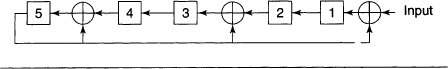
Table E.1 Steps in Shift Register Generation of CRC

An obvious question is ‘What makes a good generator polynomial?’ Perhaps the best answer is that the CRCs have been around a long time and have been studied extensively. Some well-known standards have chosen specific generating polynomials.
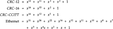
MPEG 2 Systems utilizes the 32-bit Ethernet CRC. In MPEG 1 Audio, the 16-bit CRC-16 is used. The protected fields are bits 16 to 31 of the header, the bit allocation, and scalefactor selection information.