
APPENDIX
Electronics Construction Primer
THIS APPENDIX PROVIDES a few useful hints and tips for electronic construction used in the majority of the projects in this book.
Circuits
The author likes to start a project with a vague notion of what he wants to achieve and then start designing from the perspective of the electronics.
The way to express an electronic circuit is to use a schematic diagram. The author has included schematic diagrams for all the projects in this book, so even if you are not very familiar with electronics, you should now have seen enough schematics to understand roughly how they relate to the stripboard diagrams also included.
Schematic Diagrams
In a schematic diagram, connections between components are shown as lines. These connections will use the copper strips of a piece of stripboard and the wires connecting one strip to another.
Schematic diagrams (Figure A-1) have a few conventions that are worth pointing out. For instance, it is common to place GND lines near the bottom of a diagram and higher voltages near the top of a diagram. This allows someone reading the schematic to visualize the flow of charge through the system from higher voltages to lower voltages.
When there is not enough room to draw all the connections to GND, another convention in schematic diagrams is to use the little bar symbol to indicate a connection to GND.
Schematic diagrams can be drawn with many different tools. Some of them are integrated electronics CAD (computer-aided design) products that will go on to lay out the tracks on a printed circuit board for you. By and large, these create fairly ugly-looking diagrams, and because of this the author prefers to use pencil and paper or general-purpose drawing software. All the diagrams for this book were created using Omni Group’s excellent but strangely named OmniGraffle software, which is only available for Macs. OmniGraffle templates for drawing breadboard layouts and schematic diagrams are available for download from www.dangerouslymad.com.

Figure A-1 A schematic diagram example
Component Symbols
Figure A-2 shows the circuit symbols for some common electronics.
Various standards exist for circuit diagrams, but the basic symbols are all recognizable between standards. The set used in this book does not closely follow any particular standard. I have just chosen what I consider to be the most easy-to-read approach to the diagrams.

Components
In this section, we look at the practical aspects of components: what they do, and how to identify, choose, and use them.
Datasheets
All component manufacturers produce datasheets for their products. These act as a specification for how the component will behave. They are not of much interest for resistors and capacitors, being much more useful for semiconductors and transistors, and especially integrated circuits. They will often include application notes that contain example schematics for using the components.
These are all available on the Internet. However, if you search for “BC158 datasheet” in your favorite search engine, you will find many of the top hits are for organizations cashing in on the fact that people search for datasheets a lot. These organizations surround the datasheets with pointless advertising and pretend they add some value to looking up datasheets by subscribing to their service. In reality, such web sites usually just lead to a frustration of clicking and should be ignored in favor of any manufacturer’s web sites. So, scan down the search results until you see a URL like www.fairchild.com.
Alternatively, many of the component retail suppliers such as Farnell provide free-of-charge and nonsense-free datasheets for pretty much every component they sell, which is to be much applauded. It also means that you can price and buy the components while finding out more about them.
Resistors
Resistors are the commonest and cheapest electronic components around. Their typical uses are:
![]() To prevent excessive current flowing (see any projects that use an LED)
To prevent excessive current flowing (see any projects that use an LED)
![]() In a pair or as a variable resistor, to divide a voltage
In a pair or as a variable resistor, to divide a voltage
In the “Theory” section of Chapter 12, we looked at Ohm’s law and used it to decide on a value of series resistor for an LED.
Resistors have colored bands around them to indicate their values. However, if you are unsure of a resistor, you can always find its resistance using a multimeter. Once you get the hang of it, it’s easy to read the values using the colored bands.
Each band color has a value associated with it, as shown in Table A-1.
TABLE A-1 Resistor Color Codes

There will generally be three of these bands together, starting at one end of the resistor, which is then followed by a gap, and finishes with a single band at the other end of the resistor. The single band indicates the accuracy of the resistor value. Since none of the projects in this book require very accurate resistors, there is no need to select your resistors on the basis of accuracy.
Figure A-3 shows the arrangement of the colored bands. The resistor value uses just the three bands. The first band is the first digit, the second the second digit, and the third “multiplier” band is how many zeros to put after the first two digits.

Figure A-3 A color-coded resistor
So a 270Ω resistor will have first digit 2 (red), second digit 7 (violet), and a multiplier of 1 (brown). Similarly, a 10kΩ resistor will have bands of brown, black, and orange (1, 0, 000).
Most of our projects use resistors in a very low-power manner. A quick calculation can be used to work out the current flowing through the resistor, and multiplying that by the voltage across it will tell you the power used by the resistor. The resistor burns off this surplus power as heat, so resistors will get warm if a significant amount of current flows through them.
You only need to worry about this for low-value resistors of less than 100Ω or so, because higher values will have such a small current flowing through them.
As an example, a 100Ω resistor connected directly between 5V and GND will have a current through it of I = V/R or 5/100, or 0.05 amps. The power it will use will be I × V or 0.05 × 5 = 0.25 W.
A standard power rating for resistors is 0.5 W or 0.6 W, and unless otherwise stated in the projects, 0.5-W metal film resistors will be fine.
Transistors
Browse through any component catalog and you will find literally thousands of different transistor types. In this book, the list has been simplified to the entries in Table A-2.
If it proves difficult to find a particular component, you can usually find alternatives by comparing datasheets.
The basic switch circuit for a transistor is shown in Figure A-4.
The current flowing from base to emitter (b to e) controls the larger current flowing from the collector to the emitter. If no current flows into the base, then no current will flow through the load. In most transistors, if the load has zero resistance, the current flowing into the collector will be 50 to 200 times the base current. However, we will be switching our transistor fully on or fully off, so the load resistance will always limit the collector current to the current required by the load.
TABLE A-2 Transistors Used in This Book
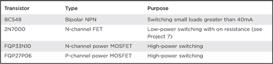
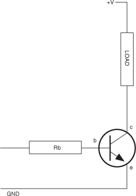
Figure A-4 Basic transistor switch circuit
Too much base current will damage the transistor and also rather defeat the objective of controlling a bigger current with a smaller one. So, the base will have a resistor connected to it.
When switching from an Arduino board, the maximum current of an output is 40mA, so we could choose a resistor that allows about 30mA to flow when the output pin is high at 5V. Using Ohm’s law:
R = V/I
R = (5 – 0.6)/30 = 147Ω
The “–0.6” is because one characteristic of bipolar transistors is that there is always a voltage of about 0.6V between the base and emitter when a transistor is turned on.
Using a 150Ω base resistor, we could therefore control a collector current of 40 to 200 times 30mA, or 1.2A to 6A, which is more than enough for most purposes.
In practice, we would probably use a resistor of 1kΩ, or perhaps 270Ω.
Transistors have a number of maximum parameter values that should not be exceeded, otherwise the transistor may be damaged. You can find these by looking at the datasheet for the transistor.
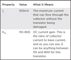
For example, the datasheet for a BC548 will contain many values. The ones of most interest to us are summarized in Table A-3.
TABLE A-3 Transistor Datasheet
Diodes
In addition to LEDs, there are also “normal” diodes. These act a bit like one-way valves, only allowing current to flow through them in one direction.
We have used them in a few of the projects in this book to prevent unwanted currents from damaging components, or when driving inductive loads like the coil in the levitator or the motors in the surveillance robot.
This “one-way” property of diodes is also what allows them to rectify a signal (see the “Theory” section of Chapter 9).
Buying Components
Thirty years ago, the electronic enthusiast living in even a small town would be likely to have the choice of several radio/TV repair shops where they could buy components and receive friendly advice. These days, a few retail outlets still sell components, like RadioShack in the U.S. and Maplin’s in the UK, but the Internet has stepped in to fill the gap, making it easier and cheaper than ever to buy components.
With international component suppliers such as RS and Farnell, you can fill a virtual shopping basket online and have the components arrive in a day or two. Shop around, because prices vary considerably between suppliers for the same components.
You will find eBay to be a great source of components. Also, if you don’t mind waiting a few weeks for your components to arrive, great bargains can be had from China. You often have to buy large quantities, but you may find it cheaper to get 50 of a component from China than 5 locally. That way, you have some spares for your component box.
Tools
When making your own projects, the following tools will be needed as a bare minimum.
![]() Multi-core wire in a few different colors; something around 0.6mm (23 SWG) wire diameter
Multi-core wire in a few different colors; something around 0.6mm (23 SWG) wire diameter
![]() Pliers and wire snips
Pliers and wire snips
![]() A multimeter
A multimeter
![]() A soldering iron
A soldering iron
![]() Solder
Solder
![]() Assorted screwdrivers
Assorted screwdrivers
Component Boxes
When you first start designing your own projects, it will take you some time to gradually build up your stock of components. Each time you are finished with a project, a few more components will find their way back to your stock.
It is useful to have a basic stock of components so you don’t have to keep ordering things when you just need a different-value resistor. You have probably noticed that most of the projects in this book tend to use values of resistors like 100Ω, 1kΩ, 10kΩ, and so on. You actually don’t need that many different components to cover most of the bases for a new project.
Boxes with compartments, which can be labeled, save a lot of time in selecting components, especially when it comes to resistors that don’t have their values written on them.
Snips and Pliers
Snips are for cutting, and pliers are for holding things still (often while you cut them).
Figure A-5 shows how you strip the insulation off wire. Assuming you are right-handed, hold your pliers in your left hand and the snips in the right. Grip the wire with the pliers close to where you want to start stripping the wire from, and then gently pinch around the wire with the snips, pulling sideways to strip the insulation away. Sometimes you will pinch too hard and cut or weaken the wire, and other times you will not pinch hard enough and the insulation will remain in tact. It’s all just a matter of practice.
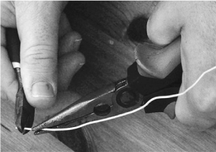
You can also buy an “automatic” wire stripper that grips and removes insulation in one action. In practice, these often only work well for one particular wire type, and sometimes just plain don’t work.
Soldering
You do not have to spend a lot of money to get a decent soldering iron. Temperature-controlled solder stations are better (Figure A-6), but a fixed-temperature mains electric iron is fine. Buy one with a fine tip and make sure it’s the kind intended for use with electronics, not plumbing.
Use narrow lead-free solder. Anyone can solder things together and make them work; however, some people just have a talent for neat soldering. Don’t worry if your results don’t look as neat as a machine-made printed circuit. They never will.
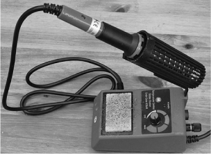
Figure A-6 A soldering iron and solder
Soldering is one of those jobs that you really need three hands for. One hand to hold the soldering iron, one to hold the solder, and one to hold the thing you are soldering. Sometimes the thing you are soldering is big and heavy enough to stay put while you solder it; other times, you will need to hold it down. Heavy pliers are good for this, as are mini vices and “helping hand”–type holders that use little clips to grip things.
The basic steps for soldering are:
![]() Wet the sponge in the soldering iron stand.
Wet the sponge in the soldering iron stand.
![]() Allow the iron to come up to temperature.
Allow the iron to come up to temperature.
![]() Tin the tip of the iron by pressing solder against it, until it melts and covers the tip.
Tin the tip of the iron by pressing solder against it, until it melts and covers the tip.
![]() Wipe the tip on the wet sponge—this produces a very satisfying sizzling sound, but also cleans off the excess solder. You should now have a nice bright silver tip.
Wipe the tip on the wet sponge—this produces a very satisfying sizzling sound, but also cleans off the excess solder. You should now have a nice bright silver tip.
![]() Touch the iron to the place where you are going to solder (in order to heat it), then after a short pause (a second or two) touch the solder to the point where the tip of the iron meets the thing you are soldering. The solder should flow like a liquid, neatly making a joint.
Touch the iron to the place where you are going to solder (in order to heat it), then after a short pause (a second or two) touch the solder to the point where the tip of the iron meets the thing you are soldering. The solder should flow like a liquid, neatly making a joint.
![]() Remove the solder and soldering iron, putting the iron back in its stand, and being very careful that nothing moves in the few seconds that the solder takes to solidify. If something does move, touch the iron to it again to re-flow the solder; otherwise, you can get a bad connection called a “dry joint.”
Remove the solder and soldering iron, putting the iron back in its stand, and being very careful that nothing moves in the few seconds that the solder takes to solidify. If something does move, touch the iron to it again to re-flow the solder; otherwise, you can get a bad connection called a “dry joint.”
Above all, try not to heat sensitive (or expensive) components any longer than necessary, especially if they have short leads.
Practice soldering old bits of wire together or solder wires to an old section of circuit board before working on the real thing.
Multimeters
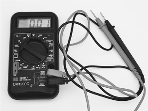
A big problem with electrons is that you cannot see them. A multimeter lets you view what they are up to. It allows you to measure voltage, current, resistance, and often other features, too, like capacitance, frequency, and more. A cheap $10 multimeter is perfectly adequate for most purposes.
Multimeters (Figure A-7) can be either analog or digital. You can tell more from an analog meter than you can from a digital, because you can see how fast a needle swings over, and how it jitters—something that isn’t possible with a digital meter, where the numbers just change. However, for a steady voltage, it’s much easier to read a digital meter since an analog meter will have a number of scales, and you have to work out which scale you should be looking at before taking the reading.
You can also get autoranging meters which, once you have selected whether you are measuring current or voltage, will automatically change ranges for you as the voltage or current increases. This is useful, but some would argue that thinking about the range of voltage before you measure it is actually a good thing.
To measure voltage using a multimeter:
![]() Set the multimeter range to voltage (start at a range that you know will be higher than the voltage you are about to measure).
Set the multimeter range to voltage (start at a range that you know will be higher than the voltage you are about to measure).
![]() Connect the black lead to GND. A crocodile clip on the negative lead makes this easier.
Connect the black lead to GND. A crocodile clip on the negative lead makes this easier.
![]() Touch the red lead to the point whose voltage you want to measure. For instance, to see if an Arduino digital output is on or off, you can touch the red lead to the pin and read the voltage, which should be either 5V or 0V.
Touch the red lead to the point whose voltage you want to measure. For instance, to see if an Arduino digital output is on or off, you can touch the red lead to the pin and read the voltage, which should be either 5V or 0V.
Measuring current is different than measuring voltage because you want to measure the current flowing through something, not the voltage at a particular point. So you put the multimeter in the path of the current you are measuring. This means that when the multimeter is set to a current setting, there will be a very low resistance between the two leads, so be careful not to short anything out with the leads.
Figure A-8 shows how you could measure the current flowing through an LED.
To measure current:
![]() Set the multimeter range to a current range higher than the expected current. Note that multimeters often have a separate high-current connector for currents as high as 10A.
Set the multimeter range to a current range higher than the expected current. Note that multimeters often have a separate high-current connector for currents as high as 10A.
![]() Connect the positive lead of the meter to the more positive side from which the current will flow.
Connect the positive lead of the meter to the more positive side from which the current will flow.

![]() Connect the negative lead of the meter to the more negative side. Note that if you get this the wrong way around, a digital meter will just indicate a negative current, but if you’ve connected an analog meter the wrong way around, it may damage it.
Connect the negative lead of the meter to the more negative side. Note that if you get this the wrong way around, a digital meter will just indicate a negative current, but if you’ve connected an analog meter the wrong way around, it may damage it.
![]() In the case of an LED, the LED should still light as brightly as before you put the meter into the circuit, letting you read the current consumption.
In the case of an LED, the LED should still light as brightly as before you put the meter into the circuit, letting you read the current consumption.
Another feature of a multimeter that is sometimes useful is the continuity test feature. This will usually beep when the two test leads are connected together. You can use this to test fuses and so on, but also to test for accidental short circuits on a circuit board, or broken connections in a wire.
Resistance measurement is occasionally useful, particularly if you want to determine the resistance of an unmarked resistor.
Some meters also have diode and transistor test connections, which can be useful in finding and discarding transistors that have burned out.
Oscilloscopes
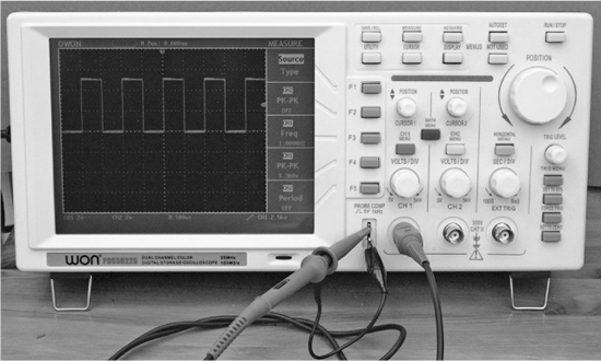
Oscilloscopes (Figure A-9) are an indispensable tool for any kind of electronics design or test where you are looking at a signal that changes over time. They are a relatively expensive bit of equipment and there are various types. One of the most cost-effective types does not have any display at all, but connects to your computer over USB. If you don’t want to risk blobs of solder on your laptop, or wait for it to boot up, then a dedicated oscilloscope is probably the answer for you.
Entire books have been written about using an oscilloscope effectively, and since every oscilloscope is different, we will just cover the basics here.
As you can see from Figure A-9, the waveform is displayed over the top of a grid. The vertical grid is in units of some fraction of volts, which on this screen is 2V per division. So the voltage of the square wave in total is 2.5 × 2 or 5V.
The horizontal axis is the time axis, which is calibrated in seconds—in this case, 500 microseconds (mS) per division. So the length of one complete cycle of the wave is 1000 mS, or 1 millisecond, indicating a frequency of 1 kHz.
Summary
Many resources are available to help you learn electronics. On the Internet, electronics forums abound, where you can post your questions and receive high-quality answers.
Books and hobby electronics magazines offer you useful projects with some words of explanation about their designs. As time goes on, you will find yourself understanding more and more.
Also, seek out clubs in your area. Radio amateur “Ham Fests” (nothing to do with pork) are a great way to meet other enthusiasts and pick up interesting bargain components.