
CHAPTER 14
Light-Seeking Microbot

SOMETIMES THE EVIL GENIUS GROWS tired of the company of his minions and needs something more stimulating and intelligent. At these times, he turns his attention to a little electronic companion: “Snailbot.”
As you can see, when compared to a AA battery (as shown in Figure 14-1), this robot is very small.
This tiny snail will slither towards a flashlight held in front of it—this in contrast to minions who will generally just freeze in terror when a light is shone in their eyes.
The project uses a small number of components and is simple to construct. It employs the recycled electric motors from disposable toothbrushes to drive the robot, and its power is supplied from a tiny snail shell–like rechargeable battery.

What You Will Need
You will need the following components to build this project. They are listing in the Parts Bin.
The last seven components are only required if you need to make a small charger for the robot. If you have a variable current power supply, you don’t need to build this part of the project.
You will also need the following tools:
![]() Soldering equipment
Soldering equipment
![]() A hot glue gun or self-adhesive pads
A hot glue gun or self-adhesive pads
![]() A hacksaw
A hacksaw
![]() A bright flashlight
A bright flashlight
Assembly (Robot)
Figure 14-2 shows the schematic diagram for the robot. See the “Theory” section at the end of this chapter for more information about how this circuit works. The basic idea is that the phototransistors control the power to the motors. The more light falling on the left phototransistor, the more power goes to the right motor. This “cross-over” arrangement will naturally cause the robot to home in on a light source.
The following step-by-step instructions lead you through making the robot. Everything apart from the motors is built onto a small piece of stripboard.
Step 1. Charge the Battery
We will not be able to test Snailbot if its battery is empty. So we should first charge it up.
If you have a bench power supply with variable current, then set the current to 10mA, clip the leads to the battery’s terminals (positive to positive), and let it charge for ten hours.
If you don’t have one, then you need to read the later section in this chapter called “Assembly (Charger)” and build the battery charger first.
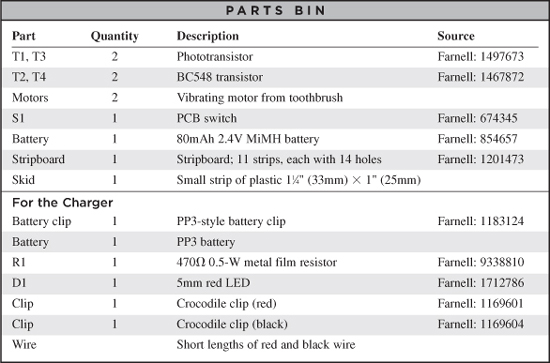
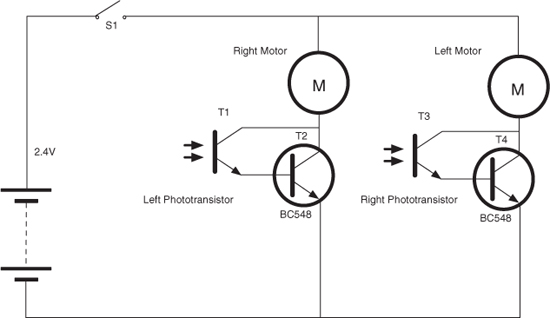
Figure 14-2 The schematic diagram
Step 2. The Stripboard
Figure 14-3 shows the stripboard layout.
Cut the stripboard into an area of 11 strips, each with 14 holes. You can do this with a strong pair of scissors or by scoring both sides of the board with a craft knife and then breaking it over the edge of a table.
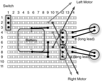
Figure 14-3 The stripboard layout
There is only one linking wire to fit to the stripboard, and this should be soldered in place first (Figure 14-4).
Next, solder in the switch and the battery. The negative lead of the battery is attached to the link, and the positive lead to a small wire passing through the board to the track below. The battery should be positioned as centrally as possible (Figure 14-5).
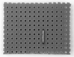
Figure 14-4 The stripboard with the link in place

Figure 14-5 The switch and battery in place
Make sure the switch is in the off position. Remember, from now on we are soldering a board that has a charged battery attached to it, so it would be quite easy to accidentally short the battery while soldering, which would likely damage it.
The transistors can now be soldered into place. The phototransistors are soldered in place, leaving their leads as long as possible to allow them to be bent into a snail-eye’s position (Figure 14-6).
Step 3. Salvage the Motors
The Evil Genius is a considerate employer and buys low-cost disposable electric toothbrushes for his minions to use when they are cleaning his teeth. Throwing these away, just because the bristles are a little frayed, seems very wasteful to any Evil Genius who likes to do a bit of recycling.
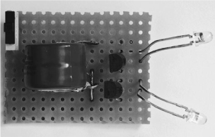
Figure 14-6 The completed board

These toothbrushes contain tiny lightweight electric motors (Figure 14-7) with a semicircular weight that makes the whole thing vibrate when the toothbrush is turned on. A typical example of such a brush is shown in Figure 14-8.

Figure 14-8 Disposable electric toothbrush
You should select toothbrushes that are of a thin design and are powered by a single AAA battery.
Extracting the motor requires a good deal of care, as it is all too easy to break off the leads that connect to the motor.
The first step is to remove the battery and then chop out the middle section from the switch assembly to the beginning of the brush. You can just hacksaw straight through, leaving a middle section.
Now comes the delicate bit. Figure 14-9 shows this middle section carefully sawn open along its length and the switch and motor assembly removed. The motor can be de-soldered and the rest of the toothbrush discarded.
Step 4. Attach the Motors
The two motors are attached to a strip of plastic 1 inch (25mm) wide (Figure 14-10). Before gluing the motors into place, bend the plastic slightly so it forms a gentle arc. This will let Snailbot slide across surfaces more easily.

Figure 14-9 Removing the switch and motor assembly
The weights on the motors are not going to be in direct firm contact with the ground, but rather the vibrations and occasional glancing contact by the weights on the motors with the ground will propel Snailbot forwards.
Notice that in Figure 14-10 one of the motor leads has been extended. You may well need to do this so the leads will easily reach their points of connection on the underside of the stripboard.
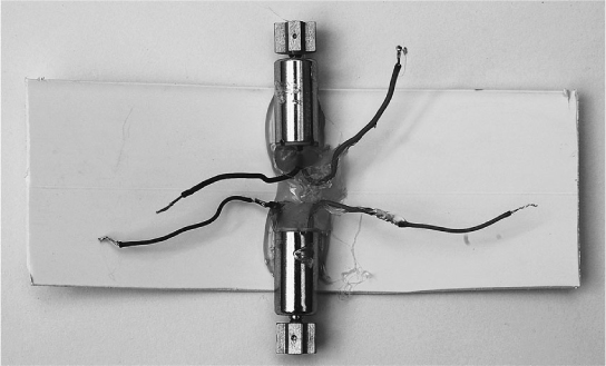
Figure 14-10 Attaching the motors
Step 5. Final Wiring and Test
Using Figure 14-3 as a guide, solder the leads of the motors to the underside of the stripboard.
We can now carry out a test to make sure everything is right before we glue it all together.
Flip the switch to the “on” position. Both motors should be still. If either or both of them are turning a little, put your hand over the phototransistors and the motors should stop. This just means your workbench is getting too much illumination, so find a darker place.
Now take a flashlight and shine it in Snailbot’s left eye. This should make the right motor whir. It should whir faster the closer you move the flashlight to it. The other motor will probably pick up some of the stray light and spin a little, too. You should, however, be able to tell that each phototransistor controls the opposite motor.
Finally, check that the motors are turning the right way to propel Snailbot forwards. If they are not, you may be able to turn the board through 180 degrees without having to re-solder the connections. If the leads are not long enough to do this, you will have to re-solder all the leads, switching the red and blue leads around for each motor.
If one of the motors is not working, go back and carefully check the wiring and make sure the phototransistor for that motor is the right way around.
Step 6. Glue Everything into Place
The stripboard is glued by its rear edge to the plastic so it is more or less centered over the motors (Figure 14-11). The excess plastic can then be cut off to the right length with a pair of scissors.
Using Snailbot
Snailbot works best on a table top or other flat surface. It does not work so well on carpet. Take a flashlight and shine it directly in the face of Snailbot and it should whir to life, chasing after the flashlight as you move it round the table top.
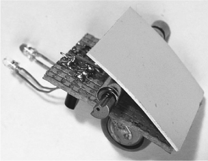
Figure 14-11 Fixing the stripboard to the plastic
Assembly (Charger)
If you have a variable current power supply, you probably do not need to make this charger. It charges Snailbot from a 9V battery and is shown in Figure 14-12.
Figure 14-13 shows the schematic diagram for Snailbot’s charger, and as you can see, it is a very simple design, comprised of a battery clip, an LED, a resistor, and two crocodile clips.
The charger has few enough components that you can just solder all the components to each other, as shown in the wiring diagram of Figure 14-14.
To use the charger, first turn the switch off. The crocodile clips attach directly to the battery.
This charger operates at about 10mA, which means a full charge will require an overnight charging of about ten hours. But once charged, you should find you get hours of fun from your Snailbot.

Figure 14-12 A simple charger for Snailbot
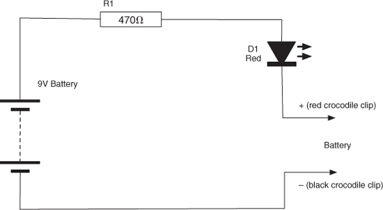
Figure 14-13 The schematic diagram for Snailbot’s charger

Figure 14-14 Snailbot charger wiring diagram
Theory
Refering back to Figure 14-2, this is a very simple design.
The phototransistors do not have sufficient amplification to drive the motors directly and so each phototransistor has a second transistor connected to it in an arrangement called a Darlington-Pair.
The smaller current flowing through the collector of the phototransistor is fed directly into the base of the second transistor, providing “double” amplification of the current.
Summary
This is a small and very simple robot. In the next and final chapter, we will scale up to make a much bigger and more capable robot—in fact, a robot with a brain, albeit a small microcontroller-based brain.