
CHAPTER 9
Covert Radio Bug

THE EVIL GENIUS LIKES TO KNOW what his enemies are saying. And what better way to discover that than to plant a bug. On the other hand, the Evil Genius considers any spying on him as an unacceptable breach of his privacy, and for this reason, this chapter also includes a “bug detector” that will let him locate bugs that may have found their way into his lair. (Figure 9-1 shows the bug and Figure 9-2 the bug detector.)


Rather than build a bug from scratch, this project cunningly uses a cheap FM transmitter of the type employed in cars to play music from an MP3 player. These devices can be acquired very cheaply and can be set to transmit at any frequency on the FM band. Ideally, this should be at a frequency not in use by a radio station, but the Evil Genius will occasionally confuse his minions by deliberately setting it to the frequency of their favorite station and barking commands at them over the transmitter.
The shocked looks on their little faces when they hear their radio addressing them personally, and in such aggressive terms, is priceless to the Evil Genius.
The Bug
FM transmitters for MP3 players expect to receive a signal from an MP3 player that is already amplified to a reasonable level. Unfortunately, microphones only produce a small electrical signal that must be amplified before anything useful can be done with it. So we have to make a little amplifier to feed the transmitter. Figure 9-3 shows the schematic diagram for the bug.
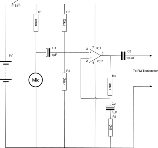
Figure 9-3 The schematic diagram
What You Will Need
You will need the components listed in the Parts Bin to build the bug.
You will also need the following tools:
![]() Soldering equipment
Soldering equipment
![]() A hot glue gun or self-adhesive pads
A hot glue gun or self-adhesive pads
![]() A hacksaw
A hacksaw
Assembly
The project is all assembled on a single piece of stripboard. The following steps will lead you through the construction.
Step 1. Prepare the Stripboard
Figure 9-4 shows the stripboard layout for the microphone amplifier.
The first step is to cut a piece of stripboard that has ten strips, each with 22 holes. Seven breaks should be made in the tracks. Make these using a drill bit, employing the bit as a hand tool by rotating it between your finger and thumb. Figure 9-5 shows the prepared board ready for the components to be soldered onto it.
Step 2. Solder the Links
Before starting on the real components, solder the four wire links into place. When this is complete, your board should look like Figure 9-6.
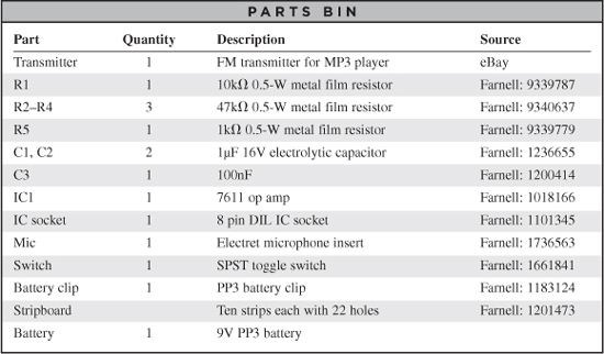

Figure 9-4 The microphone amplifier stripboard
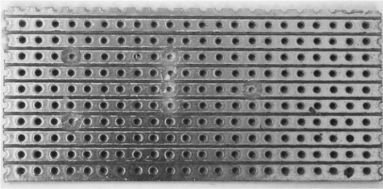
Figure 9-5 The stripboard for the bug
Step 3. Solder the Resistors
We can now solder all the resistors in place. Take special care with R5, which is soldered at an angle across one of the links. The leads of the resistor should be kept away from the wire of the link. However, it does not matter if the body of the resistor touches the link.
When all the resistors are soldered into place, your board will look like Figure 9-7.
Step 4. Solder the IC
Place the IC in position (see Figure 9-8), ensuring that it is the right way around—the little dot indicating pin 1 should be on the top left. Solder the IC into place, using the same caution as with the receiver’s construction. Like with the receiver, you may decide to use an IC socket rather than solder the IC directly.

Figure 9-6 The bug stripboard with links

Figure 9-7 The bug board with resistors
Step 5. Solder the Remaining Components
The rest of the components can now be soldered onto the board. Solder the transistor first (making sure it is the right way around), followed by the capacitors and the electret microphone insert.
The microphone that the author used was designed to be soldered to a PCB. However, you may have to solder short leads to the contacts on the microphone. Position the microphone as shown in Figure 9-8 so it is pointing away from the rest of the electronics.
The microphone also must be connected the correct way around. The contact that is connected to the case should be the negative lead, which should be the lower contact on the stripboard. You may need to test this with a multimeter. If the transmitter does not work, try the microphone the other way around.
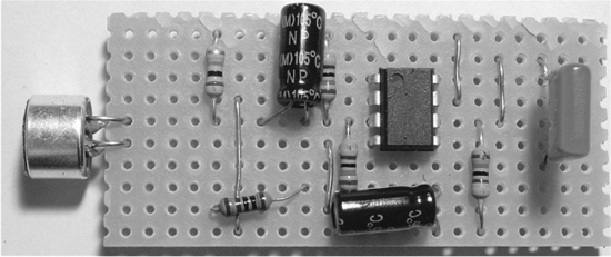
Figure 9-8 The completed transmitter stripboard
Step 6. Prepare the Transmitter
Figure 9-9 shows the FM transmitter in its unmodified state. These things are designed to fit into your car’s cigarette lighter socket and have a trailing lead that plugs into your MP3 player. The unit has a screen and some buttons that allow you to select the frequency on which it broadcasts. You would then tune your car radio to that frequency to be able to hear your MP3 player through the car’s speaker system.
These devices can be bought very cheaply, and many types are available on eBay for a few dollars.
Although designed to operate from the car’s 12V power supply, these units normally contain a voltage regulator that drops the voltage to 5V. This means they are equally happy operating from a 9V PP3 battery.
If you take your FM transmitter apart, it should look something like Figure 9-10.
On the left-hand side, you can see the power leads connected to the car accessory plug. These can be cut off, leaving leads of two or three inches that can be stripped and tinned, and made ready for soldering. This unit also had wires that lead to a backup battery (toward the bottom of Figure 9-10), a setup that was designed to remember the radio’s frequency setting in between uses of the device. This feature was deemed an unnecessary complication and those leads can be cut off. Finally, the audio lead can be shortened, stripped, and tinned, leaving a raw module like that in Figure 9-11.
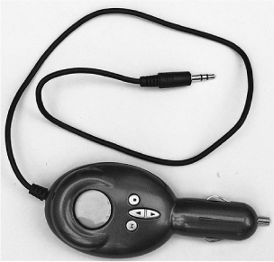
Figure 9-9 FM MP3 car transmitter

Figure 9-10 FM transmitter disassembled

Figure 9-11 FM transmitter with leads trimmed
The design of this unit used an LCD screen that was simply pressed against a connector leading to the circuit board. This required the board to be attached to the case, to hold the display in place. If your unit’s screen is attached more strongly, you can leave the case off entirely. In this instance, we attached the case but cut off the long plug part with a hacksaw (Figure 9-12).
In Figure 9-12, you can also make out crocodile clips that were connected to a 9V supply to make sure our transmitter wasn’t damaged during its surgery. The audio lead has also been stripped and tinned. Note that the left and right internal wires have been soldered together. Our bug will not be in stereo.
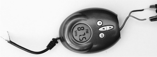
Figure 9-12 FM transmitter reduced to basics
Step 7. Wire Everything Together
Referring back to Figure 9-4, wire up the project so we can test it before fitting it into a project box.
Solder the red lead of the battery clip to the stripboard, and then solder the black negative lead from the battery clip to the negative connection on the stripboard.
Next, attach the power leads of the FM transmitter to the stripboard and finally the audio input of the transmitter to the stripboard. The shielding of the audio lead does not need connecting as it will already be connected to ground. Both the left and right audio wires inside the shielding should be connected together before attaching them to the stripboard (Figure 9-13).
Step 8. Test the Bug
Attach the battery and set the FM transmitter to an unused frequency. Place it near the TV or another sound source, and retire to a neighboring room with a portable FM radio tuned to the same frequency.
You should be able to hear the sound coming from the bug.
Using the Bug
Unlike you, the reader, the Evil Genius has no qualms about listening to other people’s conversations. He will conceal his bug in a small box—perhaps a pack of cards—and retire to another room with his transistor radio and a flask of warm milk. His minions have learned that their master likes to operate in this fashion, and so they always say nice things about him. This pleases the Evil Genius.
A Bug Detector
One of the interesting things about this bug is that because of its short range and low power, it broadcasts at a strength that is no stronger than the radio signals received from commercial radio stations in the FM band. This makes it almost impossible to build a detector to find out if you are being bugged using this kind of device.
A lot of modern bugs are based on cell phone technology. They are basically a phone that can be concealed somewhere and turned on remotely either by a phone call or SMS message. It is much easier to detect such bugs—at least when they are on.
So, we are going to build a detector for these kinds of bugs. The Evil Genius also finds it a good way to detect minions using their cell phones when they should be doing their minion homework. This particularly annoys the Evil Genius, especially when their phones are better than his. So having detected such errant behavior, the Evil Genius can enjoy a good cell phone stomping session.
The detector looks like a detector should look (Figure 9-14), with a proper analog meter, whose needle swings over to indicate the strength of the microwave frequencies that cell phones use.
The antenna is attached using screw terminals to allow easy switching between different antenna designs. This will allow you to experiment with different designs to work with the different frequencies at which mobile phones operate.
Figure 9-15 shows the schematic diagram for the bug detector.
The design uses a germanium diode as a detector and amplifies the weak signal from the phone using an operational amplifier. For a more detailed description, see the “Theory” section that follows.
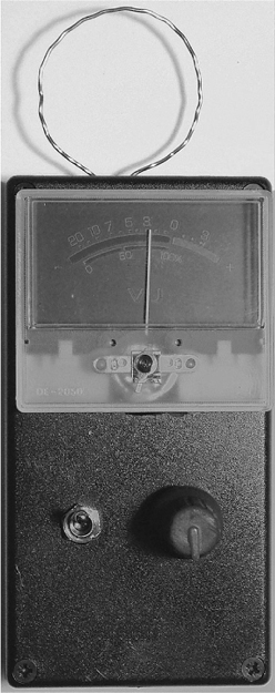
Figure 9-14 Cell phone bug detector
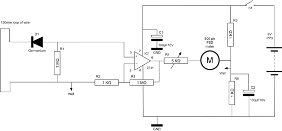
Figure 9-15 Schematic diagram for the cell phone detector
What You Will Need
You will need the components listed in the Parts Bin to build the cell phone detector.
You will also need the following tools:
![]() Soldering equipment
Soldering equipment
![]() A drill and assorted drill bits
A drill and assorted drill bits
![]() A hot glue gun or self-adhesive pads
A hot glue gun or self-adhesive pads
Assembly
The bug detector is built onto a small piece of stripboard, with the meter variable resistor and switch mounted in the lid of the plastic case. The instructions below will lead you step by step through the process of building the detector.
Step 1. Prepare the Stripboard
Figure 9-16 shows the stripboard layout for the cell phone detector.

Figure 9-16 The stripboard layout for the cell phone detector

The first step is to cut a piece of stripboard that has 12 strips, each with 12 holes. Five breaks must then be made in the tracks. Make these using a drill bit—that is, just using it as a hand tool and rotating it between your finger and thumb. Figure 9-17 shows the prepared board ready to have the components soldered to it.
Step 2. Solder the Links and Resistors
Before starting on the real components, solder the six wire links into place (Figure 9-18). Note that you will need to bend some of the links to fit them all on the board.
We can now solder all the resistors in place and also solder in the diode. Be careful to get the diode the correct way around.
When all the resistors and the diode are soldered into place, your board will look like Figure 9-19.
Step 3. Solder the IC
Solder the IC next. Make sure that pin 1 is at the top of the board. Pin 1 is marked by a little circle on the IC package. If you are worried about soldering the IC directly onto the stripboard, you can use an eight-pin IC socket.
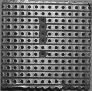
Figure 9-17 The cell phone detector stripboard ready for soldering

Figure 9-18 The board with links

Figure 9-19 The board with resistors and diode
Note how the IC sits on top of one of the links. Make sure that none of the links are touching the IC pins.
When the IC is in place, the board should look like Figure 9-20.

Figure 9-20 The board with the IC in place
Step 4. Solder the Capacitors and Terminal Block
We can now solder in the terminal block and the capacitors. Make sure the capacitors are the correct way around. They should both have the longer positive lead toward the bottom of the stripboard.
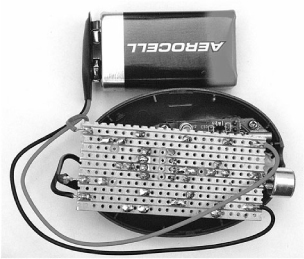
The board with all the components in place is shown in Figure 9-21.
Step 5. Make an Antenna
The antenna is just a loop of wire 150mm in length. The author used 20-AWG enamel-coated wire. The thickness is not critical, but the wire should be thick enough to hold its shape. If you use enameled wire, you will have to strip off the enamel at the wire ends. Use a pair of snips or a knife to do this before inserting it into the terminal block (Figure 9-22).
Step 6. Test the Bug Detector
Before fixing everything into a box, we need to test out the circuit and make sure everything works as it should. So, connect up the components as shown in the wiring diagram of Figure 9-23.

Figure 9-21 The board with all the components in place
Start by soldering short leads to the center and one end of the variable resistor. One of these leads will be connected to the negative terminal of the meter. Another short lead should be soldered from the positive lead of the meter to the Vref connection track on the stripboard next to C1.
The other lead from the variable resistor should be soldered to the R4 strip on the breadboard.
We now just need to connect up the switch and battery clip. Cut the positive (red) lead of the battery clip about halfway along its length and solder in the switch, as shown in Figure 9-23. Then, solder the remainder of the positive battery clip lead between the switch and the +9V strip on the stripboard.
Turn the variable resistor to its halfway position, attach the battery, and turn on the switch. The meter should move slightly away from its zero position. If it does not move, or the meter pings hard over to the far side, then turn off the power immediately and carefully check your circuit.
Now get a mobile phone and, holding it close to the antenna, make a call to your voicemail. You should see the meter start to twitch and then move quite vigorously. You’ll find that the meter is sensitive enough to detect a phone call from a few meters away.

Figure 9-22 The antenna attached to the stripboard
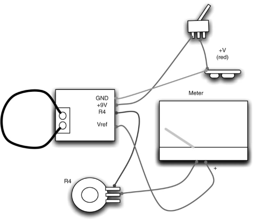
Figure 9-23 Wiring diagram for the cell phone detector
Step 7. Box the Project
Assuming everything is working, we can put the project in a box if we like. As with all the projects in this book, first find a box that is big enough, and then work out where the project parts will fit before drilling holes for the switch variable resistor and the meter.
Figure 9-24 shows the layout of the components in the box.
Fix the stripboard in place at the end of the box, with the terminal block pressed against the end of the box. Use self-adhesive pads or blobs of glue from a hot glue gun. Drill two small holes for the wire ends of the antenna. This is going to be outside of the box, so the holes need to line up with the terminal block.
Theory
Referring back to Figure 9-15, a small signal in the gigahertz frequency will be induced in the loop antenna. This is rectified (see Figure 9-25) by the germanium diode. A germanium diode is used because it has a much lower voltage drop than the usual silicon diode (0.3V compared to 0.6V). This makes it more sensitive.
To measure how strong the signal is, think about the average signal. If it is not rectified, then half the time it is positive and half the time it is negative, making the average signal always zero. By rectifying it, we chop off the negative bit, making our average signal positive in proportion to how big the waves are.
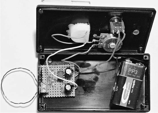
Figure 9-24 Fitting the cell phone detector into a box

Figure 9-25 Rectifying the signal
This signal is oscillating at over a billion times a second, so we do not need to consider smoothing it with a capacitor since the rest of the electronics won’t be fast enough to see anything more than an average anyway.
The next step is to amplify that weak signal and we use an amplifier IC to do this. The type of amplifier we use is called an operational amplifier, or “op amp” for short. This kind of amplifier has two inputs, one positive and one negative. It amplifies the difference between these two inputs. However, to make the amplifier stable, you always operate it with feedback. This passes a portion of the amplified signal back to the input, letting you control exactly how much it amplifies (its gain).
In the arrangement we’ve used here, which is called “non-inverting,” we employ the negative input just for feedback and pass the signal we want to amplify into the positive input.
The output will be the input multiplied by the gain. The gain is set by the degree of negative feedback and can be calculated as 1 + R3 / R2. Since R3 is 1MΩ, and R2 is 1K, the gain is 1001. Op amps are really designed to be operated with a split supply. For example, +9V, GND, and –9V. To do this would require two batteries, which we do not really want. So, instead we use the arrangement of R5, R6, and C2 to provide a reference voltage of about 4.5V, halfway between GND and 9V.
Summary
Now the Evil Genius has a means of bugging people, and also a means of detecting when he’s been bugged (albeit only if the bug is of the cell phone variety).
In the next project, we will make a system for sending sound over a laser beam. No radio waves means no way of eavesdropping with a radio receiver, and so the Evil Genius can once again communicate securely.