
CHAPTER 8
Persistence-of-Vision Display

ATOP THE EVIL GENIUS’ LAIR, there is a sign that is holographic in appearance and displays the slowly rotating message “Hello.” The sign uses a vertical line of multicolor LEDs that rotates rapidly, producing a persistence-of-vision effect (see Figure 8-1). The main purpose of such a display is to help the Evil Genius find his way back to the lair, exhausted after a hard day achieving world domination.
This project has two parts, an Arduino microcontroller-based LED unit that sits on top of the second part of the project: the motor and motor control unit. This controls the speed of the motor that spins the arm with the LEDs.

Figure 8-1 Persistence-of-vision display
WARNING!
This project has two potentially hazardous aspects.
![]() It spins around quite fast, so if you stick your fingers into the path of the wooden arm while it is spinning, it will hurt!
It spins around quite fast, so if you stick your fingers into the path of the wooden arm while it is spinning, it will hurt!
![]() The entire project is based on bright flashing lights. If you suffer from epilepsy, then steer clear of it.
The entire project is based on bright flashing lights. If you suffer from epilepsy, then steer clear of it.
Arduino
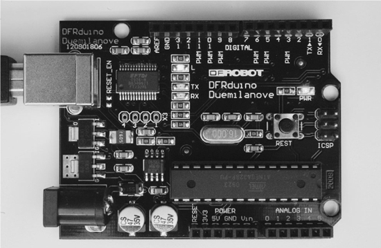
Central to this project is the Arduino microcontroller board (Figure 8-2). We will use these boards again in Chapters 13 and 15.
Arduino interface boards provide the Evil Genius with a low-cost, easy-to-use technology to create their evil projects.
Arduino is a small microcontroller board with a USB plug to connect to your computer and a number of connection sockets that can be wired up to external electronics such as motors, relays, light sensors, laser diodes, loudspeakers, microphones, and so on. They can either be powered through the USB connection from the computer, or from a 9V battery, and can be controlled from the computer or programmed by the computer and then disconnected and allowed to work independently.
At this point, the Evil Genius might be wondering which top secret government organization they need to break into in order to acquire an Arduino.
Alas, no evil deeds are necessary to acquire one of these devices. The Evil Genius need go no further than their favorite online auction site or search engine. Since the Arduino is an open-source hardware design, anyone is free to take the designs and create his own clones of the Arduino and sell them—thus, the market for the boards is competitive. An official Arduino costs about US$30 and a clone often less than US$20.
The name Arduino is reserved by the original makers of the Arduino. Clone Arduino designs often have the letters “duino” on the end of their name—for example, Freeduino or DFRduino.
The software for programming your Arduino is easy to use and also freely available for Windows, Mac, and LINUX computers, at no cost.
Although Arduino is an open-source design for a microcontroller interface board, it is actually more than that since it encompasses the software development tools you need to program an Arduino board, as well as the board itself. There is a large community of construction, programming, electronics, and even art enthusiasts willing to share their expertise and experience on the Internet.
In this book, we use the Arduino Duemilanove, sometimes called Arduino 2009; however, the recently released Arduino Uno will also work just fine.
When making a project with an Arduino, you need to download programs onto the board using a USB lead between your computer and the Arduino. This is one of the most convenient things about using an Arduino. Many microcontroller boards use separate programming hardware to get programs into the microcontroller. With Arduino, it’s all contained on the board itself.
On both edges of the board are two rows of connectors. The row at the top of the diagram is mostly digital (on/off) pins, and any marked with “pwm” can be used as analog outputs.
The bottom row of connectors has useful power connections on the left, and analog inputs on the right.
These connectors are arranged like this so that so-called “shield” boards can be plugged into the main board in a piggyback fashion. It is possible to buy readymade shields for many different purposes. The following are just a few of the things they are used for.
![]() Connection to Ethernet networks
Connection to Ethernet networks
![]() LCD displays and touch screens
LCD displays and touch screens
![]() XBee (wireless data communications)
XBee (wireless data communications)
![]() Sound
Sound
![]() Motor control
Motor control
![]() GPS tracking
GPS tracking
Searching the Internet for “Arduino Shields” should produce lots of interesting results if you want to go further into the world of Arduino. In fact, one book in the Evil Genius series by this author concentrates solely on the Arduino. Its title: 30 Arduino Projects for the Evil Genius.
Persistence-of-Vision Display
We are going to start by assembling the LED and Arduino module. The finished module is shown in Figure 8-3 and its schematic diagram in Figure 8-4.
The LED module uses nearly all the input/output pins available on the Arduino board in order to drive each of the LEDs separately. Each LED has a current limiting resistor, which is 150Ω for the red LEDs and 100Ω for the other colors.

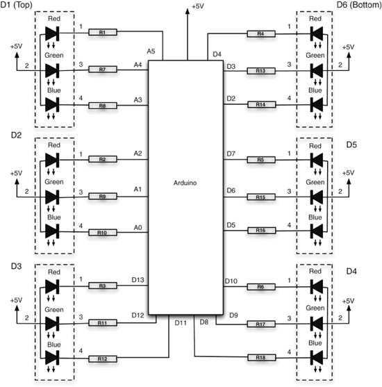
Figure 8-4 Schematic diagram for the LED module
What You Will Need
You will need the following components to build the Arduino-controlled LED module. They are listed in the Parts Bin.
Later in this chapter, you will find the component listing for the motor controller.
The LEDs can be quite expensive when bought from a regular component supplier. You can get a better deal on eBay. When buying them, make sure they are common anode (the positive connections of each of the three LEDs connected together) and that the pin connections are the same as indicated in the schematic diagram of Figure 8-4. It is always worth checking the LED’s data sheet.
LEDs with a diffuse lens produce a better effect than those with a clear lens. However, if only clear-lens LEDs are available, you can gently roughen the front of the LED with sandpaper to give it a frosted effect.
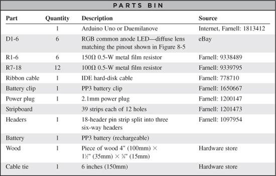
To connect the LEDs to the Arduino board, we will use ribbon cable. A great source of ribbon cable is an IDE-style hard-disk cable scavenged from an old computer. Even if you have to buy a new cable, the sheer volume of production of these cables means they are much cheaper than buying ribbon cable by itself.
You will also need the following tools:
![]() Soldering equipment
Soldering equipment
![]() An electric drill and assorted drill bits
An electric drill and assorted drill bits
![]() Wood saw
Wood saw
![]() A computer to program the Arduino
A computer to program the Arduino
![]() A USB-type A-to-B lead (as used for printers)
A USB-type A-to-B lead (as used for printers)
Step 1. Prepare the Stripboard
Figure 8-5 shows the stripboard layout for the LED module.
The first step is to cut a piece of stripboard that has 39 strips each of 12 holes. You must then make 18 breaks in the tracks. Do this by using a drill bit—that is, employing it as a hand tool—rotating it between finger and thumb. Figure 8-6 shows the prepared board, ready to be soldered with the components.
You will also need to drill two larger holes at the bottom of the stripboard to attach it to the wooden arm.

Figure 8-5 The stripboard layout for the LED module

Figure 8-6 The LED module stripboard ready for soldering
Step 2. Solder the Links and Resistors
Before starting on the real components, solder the four wire links into place.
Afterward, solder all the resistors in place. Once done, your board will look like Figure 8-7.

Figure 8-7 The board with resistors and links
Step 3. Solder the LEDs
Place the LEDs into position, ensuring they are the correct way around. Then, starting at one end of the board, solder each LED into place. To keep the LEDs as straight as possible, solder one lead of the LED, then reposition the LED from the front if required and solder the other leads into place.
When all the LEDs are soldered into place, the board should look like Figure 8-8.

Figure 8-8 The board with all components in place
Step 4. Solder the Ribbon Cable
We are going to use three lengths of ribbon cable, each with six wires. At the stripboard end, the cables will be soldered into place, and at the other end, the ribbon cable will be soldered to header pins so we can easily connect and disconnect the Arduino board.
Begin by cutting the ribbon cable into three lengths each of six wires; the lengths should be roughly 4½ inches (120mm), 3½ inches (90mm), and 2 inches (50mm). Then, strip the ends of all the wires. This is a tedious job as there are 36 ends to be stripped. When all the ends are stripped, they need tinning with solder.
Solder each lead to a header strip (Figure 8-9) and then push the wires on the other end of the board through from the front of the stripboard and solder the lead in place, using the diagram from Figure 8-5 as a guide.
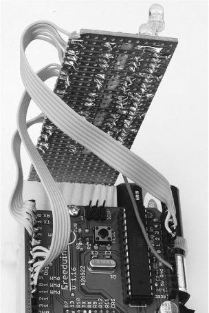
Figure 8-9 Connecting the header strip
Once all the cables are attached, it only remains to solder a wire for the +5V supply to the stripboard. We used solid core wire attached to the back of the stripboard for this. The other end of the wire can then be pushed into the Arduino board without the need for a header pin.
Step 5. Connect Up
We can now try out our hardware. Connect the pin headers and +5V lead to the Arduino board using Figure 8-9 as a guide.
While testing, we can power the unit from the USB connection to the computer, so attach the Arduino to your computer.
Step 6. Set Up Your Computer with Arduino
To be able to program our Arduino board with the control software for the LED module, we first need to install the Arduino development environment on our computer.
The exact procedure for installing the Arduino software depends on what operating system you use on your computer. But the basic principal is the same for all.
1. Install the USB driver, which allows the computer to talk to the Arduino’s USB port. It uses this for programming and sending messages.
2. Install the Arduino development environment, which is the program you run on your computer that enables you to write programs and download them to the Arduino board.
The Arduino web site (www.arduino.cc) contains the latest version of the software.
Installation on Windows
Follow the download link on the Arduino home page (www.arduino.cc) and select the download for Windows. This will start the download of the zip archive containing the Arduino software, as shown in Figure 8-10. You may well be downloading a more recent version of the software than the version 21 shown. This shouldn’t matter, but if you experience any problems, refer back to the instructions on the Arduino home page where you will find the most up-to-date information.
The Arduino software does not distinguish between different versions of Windows. The download should work for all versions, from Windows XP onwards. The following instructions are for Windows XP.
Select the Save option from the dialog and save the zip file onto your desktop. The folder contained in the zip file will become your main Arduino directory, so now unzip it into C:Program FilesArduino.
You can do this in Windows XP by right-clicking the zip file to show the menu of Figure 8-11 and selecting the Extract All… option. This will open the Extraction Wizard, shown in Figure 8-12.
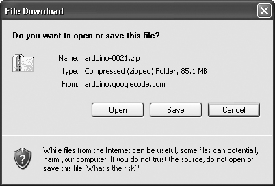
Figure 8-10 Downloading the Arduino software for Windows
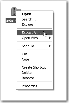
Figure 8-11 The Extract All menu option in Windows
Click Next and then modify the folder to extract files to be C:Program FilesArduino, as shown in Figure 8-13. Click Next again.
This will create a new directory for this version of Arduino (in this case, 21) in the folder C:Program FilesArduino. This allows you to have multiple versions of Arduino installed at the same time, each in its own folder. Updates of Arduino are fairly infrequent and historically have always kept compatibility with earlier versions of the software. So, unless there is a new feature of the software you want to use, or you have been having problems, it is by no means essential to keep up with the latest version.

Figure 8-12 Extracting the Arduino file in Windows
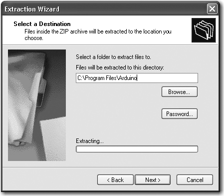
Figure 8-13 Setting the directory for extraction
Now that we have got the Arduino folder in the right place, we need to install the USB drivers.
If you are using the Arduino Uno, this process is a bit different from the older Duemilanove and Diecimila boards.
If you have an Uno board, plug in your board and wait for Plug and Play to fail. Afterward, open the Control Panel from the Start menu. Go to System and then Device Manager, and under COM and LPT ports, you will find the Arduino Uno. Right-click, selecting Update Driver, and navigate to the driver, which you will find in C:Program FilesArduinoarduino-0021drivers.
For the other boards, we can let Windows help us by plugging in the Arduino board to trigger the Windows Found New Hardware Wizard, shown in Figure 8-14.

Figure 8-14 Windows Found New Hardware Wizard
Select the option “No, not this time,” and then click Next.
On the next screen (Figure 8-15), click the option to install from a specified location, enter or browse to the location C:ProgramFilesArduino arduino-0021driversFTDI USB Drivers, and then click Next. If you download a newer version, you will have to change “0021”, in the path above, to the version you downloaded.
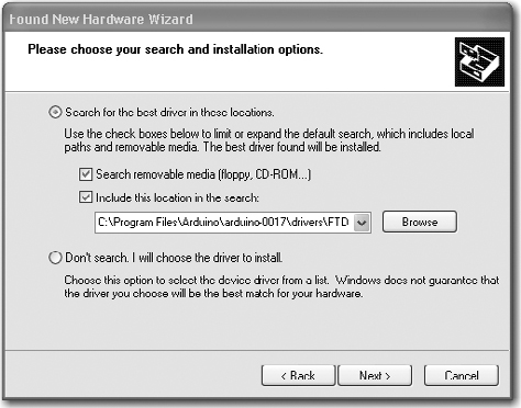
Figure 8-15 Setting the location of the USB drivers
The installation will then complete and you are ready to start up the Arduino software itself. To do this, go to My Computer, navigate to C:Program FilesArduinoarduino-0021, and click the Arduino icon, as shown in Figure 8-16. The Arduino software will now start.

Figure 8-16 Starting the Arduino software from Windows
Note that no shortcut is created for the Arduino program, so you may wish to select the Arduino program icon, right-click it, and create a shortcut you can then drag to your desktop.
The next two sections describe this same procedure for installing on Mac and LINUX computers, so if you are a Windows user, you can skip these sections.
Installation on Mac OS X
The process for installing the Arduino software on the Mac is a lot easier than on the PC.
As before, the first step is to download the file. In the case of the Mac, it is a disk image file. Once downloaded, it will mount the disk image and open a Finder window, as shown in Figure 8-17. The Arduino application itself is installed in the usual Mac way by dragging it from the disk image to your Applications folder.
The disk image also contains an installer package for the USB drivers. If you are using an Arduino Uno, you do not need this. For older boards, just perform the following instructions.
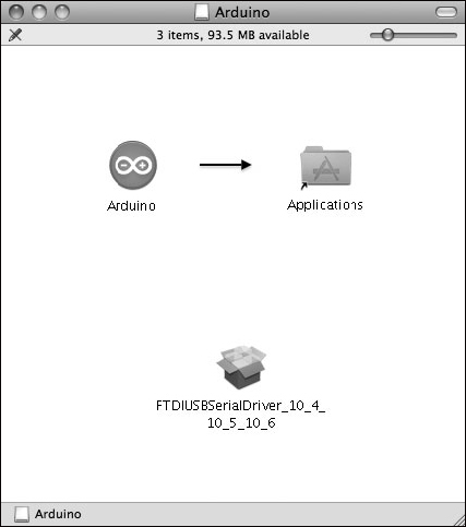
Figure 8-17 Installing the Arduino software on Mac OS X
When you run the installer, simply click Continue until you come to the select disk screen where you must choose the hard disk before clicking Continue again. (See Figure 8-18.)

Figure 8-18 Installing the USB drivers on Mac OS X
You can now find and launch the Arduino software in your Applications folder. Since you will use it frequently, you may wish to right-click its icon in the dock and set it to Keep In Dock.
You can now skip the next subsection, which is for installation on LINUX.
Installation on LINUX
Many different LINUX distributions exist, and for the latest information, refer to the Arduino home page. However, for most versions of LINUX, installation is very straightforward. Your LINUX will probably already have installed the USB drivers, the avr-gcc libraries, and the Java environment that the Arduino software needs.
So, if you are lucky, all you will need to do is download the tgz file for the Arduino software from the Arduino home page (www.arduino.cc), extract it, and this will be your working Arduino directory.
If, on the other hand, you are unlucky, then as a LINUX user you are probably already adept at finding support from the LINUX community for setting up your system. The prerequisites you will need to install are Java Runtime 5 or later and the latest avr-gcc libraries.
Googling the phrase “Installing Arduino on SUSE LINUX,” or whatever your distribution of LINUX is, will no doubt find you lots of helpful material.
Configuring Your Arduino Environment
Whatever type of computer you use, you should now have the Arduino software installed on it. You must next make a few settings. You need to specify the port that is connected to the USB port for communicating with the Arduino board and we must specify the type of Arduino board we are using. But first you need to connect your Arduino to your computer using the USB port or you will not be able to select the serial port.
The serial port is set from the Tools menu, as shown in Figure 8-19 for the Mac and Figure 8-20 for Windows—the list of ports for LINUX is similar to the Mac.
If you use many USB or Bluetooth devices with your Mac, you are likely to have quite a few options in this list. Select the item in the list that begins with dev/tty.usbserial.
On Windows, the serial port can just be set to COM3.
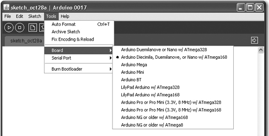
We can now select the board we will use from the Tools menu, as shown in Figure 8-21. Select the option for the board you are using.
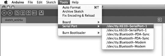
Figure 8-19 Setting the serial port on the Mac

Figure 8-20 Setting the serial port on Windows
Step 7. Program the Arduino Board
Without connecting the power supply to the board, connect a USB cable between your computer and the Arduino board. You should see the red power LED come on, and if it is a new board, a small LED in the middle of the board will be flashing slowly.
Two Arduino sketches for this project are provided at www.dangerouslymad.com: povtest and pov. Install povtest by launching the Arduino software and pasting the code for povtest, which can be found at the web site, into a new project window (see Figure 8-22). Save the project to a convenient location on your computer.
To actually upload the software onto the Arduino board so it can function without the computer, click the Upload button on the toolbar. There will now be a furious flashing of little lights on the board as the program is installed on the Arduino board.
Step 8. Test the LED Module
When the Arduino automatically starts after the sketch is uploaded, if all is well, it will start a test sequence. Each LED in turn will cycle through the seven possible colors it can display: red, green, yellow, blue, mauve, cyan, and finally white.
If any of the LEDs do not light or do not show all seven colors, make a note of the problem and refer back to the schematic diagram of Figure 8-3. Check your wiring and look for accidental solder bridges between tracks on the stripboard.
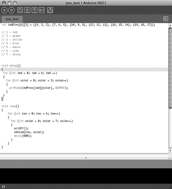
Figure 8-22 Loading the povtest sketch
If the colors or the LED order seem all mixed up, you probably have one of the header pins to the Arduino the wrong way around.
Step 9. Make the Battery Connector
To power the project from a PP3 9V battery, we need to make ourselves a small lead that has a PP3 battery clip on one end and a 2.1mm power plug on the other. Figure 8-23 shows the semi-assembled lead. The red positive wire from the battery lead is connected to the center connection of the plug and the back lead to the outside connection.
Keep the wires on the lead fairly short; otherwise, when the LED unit spins, the lead will fly out like a flail.
Step 10. Assemble the Woodwork
Well, woodwork rather overstates it. We just need a short strip of wood on which to mount the Arduino board and the LED stripboard. The length of the board is not critical, but it is a good idea to keep the overall weight of the module as low as possible. The arrangement of the components on the strip of wood is shown in Figure 8-24.
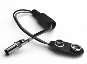
Figure 8-23 The battery clip for the LED unit
The stripboard is screwed to one end of the wood. Be careful not to screw the screws in too tight, as the stripboard will crumble if compressed too hard. The rechargeable PP3 battery is fixed to the side of the wood using a cable tie.
Apart from attaching the assembly to a motor, which we will deal with in the next section, that’s about it for the LED assembly.
Motor Controller
We need to be able to control the speed of the motor, because it must match the speed at which the LEDs switch from displaying one column to the next. There is no sensor to automatically synchronize the LEDs with the spinning motor. It’s actually more fun without this, as the letters can be made to process around the display by tweaking the motor’s speed.
You can buy readymade DC motor controllers, and if you do not want to make your own, this is probably the best option.
For those of you who want to make their own motor controller, please read on.
The motor controller uses our old friend, the 555 timer IC (Figure 8-25).

Figure 8-24 The components arranged on the wood
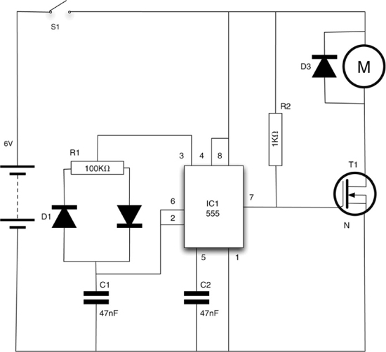
Figure 8-25 The schematic diagram of the motor controller
What You Will Need
To build the motor controller module, you will need the following components shown in the Parts Bin on the next page.
When sourcing a motor, try and find one with a mounting bracket, as this makes it much easier to fix it to the base. The motor the author used came in an educational kit.
Step 1. Prepare the Stripboard
Figure 8-26 shows the stripboard layout for the motor speed controller module.
The first step is to cut a piece of stripboard that has ten strips each of 20 holes. Six breaks must then be made in the tracks. Make these using a drill bit, which is used as a hand tool, rotating it between finger and thumb. Figure 8-27 shows the prepared board ready for the components to be soldered to it.
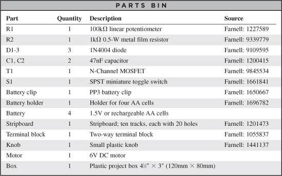
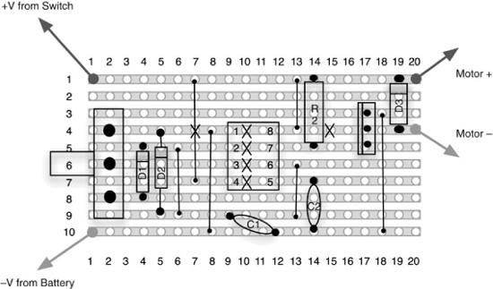
Figure 8-26 The stripboard layout for the motor controller module

Figure 8-27 The motor controller module stripboard ready for soldering
The three holes for the variable resistor may need enlarging with a drill.
Step 2. Solder the Links Resistor and Diodes
Before starting on the real components, solder the three wire links in place and then the resistors. Once done, your board should look like that in Figure 8-28.
Step 3. Solder the Remaining Components
We can now solder the rest of the components, starting with those lowest in profile. Solder the IC first, and then the capacitors and transistor.
Finally, fit the variable resistor. If enlarging the holes in the stripboard for the variable resistor has removed some of the track, then after putting the variable resistor in place, bend the leads over toward the center of the board so they can be soldered over a few holes worth of track.

Figure 8-28 The board with resistor, diodes, and links
We are also going to attach a screw terminal for connecting the motor leads. So, solder a pair of short half-inch (10mm) wires to the appropriate holes (see Figure 8-26). You should find that some of the snipped resistor leads should be about the right length.
The completed board is shown in Figure 8-29.
Step 4. Wire Up the Motor Controller
This step is straightforward, because the variable resistor is already mounted on the stripboard, so the only things that need wiring up are the switch, the battery clip, and the motor itself.
Figure 8-30 shows how the motor controller is wired up.
Platform
We now need to construct a base containing the motor and a motor controller to drive the small DC motor that will turn our LED module. The motor will vibrate when the LED arm is attached, so it is a good idea to build a solid base for the project.
The base the author used takes this to an extreme and is constructed from reclaimed two-by-four wood, crudely screwed together (Figure 8-31).
The dimensions of this are really not critical at all, as long as the motor can be mounted in such a way that its spindle is not impeded and there is access to the terminals of the motor to solder leads to them.
Putting It All Together
We can now test the motor controller before we fit it into a box. Attach the batteries and the motor. Turn the switch on and the motor should whir. The variable resistor should allow the speed of the motor to be altered from stationary to fast. Leave the knob at the slow end for now.
If everything is okay, we can fit the motor controller and batteries into a box (Figure 8-32). Holes will need to be drilled for the variable resistor and switch. It is a good idea to lay all the parts inside the box and make sure they all fit before you start drilling holes.
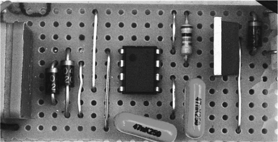
Figure 8-29 The completed motor controller stripboard
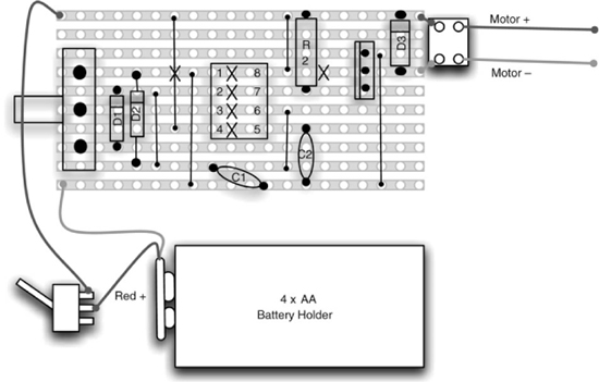
Figure 8-30 The motor controller wiring diagram
We are going to need a means of attaching a motor spindle to the bottom of the wood. This is quite tricky because it needs to keep the wood as flat as possible while giving a tight connection to the motor spindle. You will need your motor on hand to try out the size.
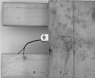
Figure 8-31 A wooden base for the motor
The author used the spindle from a broken CD drive. This had four screw holes that could be attached to the wooden arm, as well as a central hole that was a little too small for the motor spindle but that was carefully drilled to the correct size for a tight fit. (See Figure 8-33.)
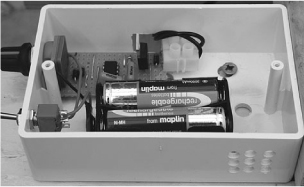
Figure 8-32 The motor controller and batteries boxed
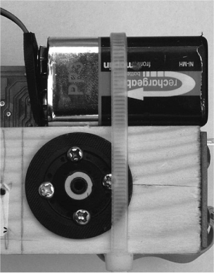
Figure 8-33 Attaching the arm to the motor
This is where, as Evil Geniuses, you must use your inventiveness and scour your junk boxes for a means of attaching your motor.
When attaching the motor, it is important for the spindle to enter the arm as close to the arm’s center of gravity as possible to minimize vibrations. You can determine this point by finding the line along the length of the arm at which it just balances. Balancing the arm on a nail works. The spindle should also be perpendicular to the wooden arm, otherwise the whole arm will vibrate up and down, spoiling the persistence-of-vision effect.
Before we turn it on, we need to install the real sketch onto the Arduino, rather than the sketch we were using to test the LEDs. So, go to www.dangerouslymad.com and copy the pov script into a new Arduino project and upload it to the board.
That’s it. Time to turn it on and try it out! Connect the battery of the arm to the socket of the Arduino board, and after a moment the LEDs should begin to flash. Now turn on the motor and slowly increase the speed. If things start to feel unstable, turn everything off and try balancing the arm better or use a different means of connecting the arm to the spindle. Be careful at this stage, because the vibrations may loosen the arm, causing it to fly off and potentially break or hurt someone.
You will start to pick out some fast-moving letters. Concentrate on one of the letters and adjust the speed of the motor until the letters stands still. You should then be able to set the letters to appear to progress around the cylinder of light by adjusting the speed slightly.
Changing the Message
In the “Theory” section later in this chapter, we explain just how the software works, but for now you are probably wondering how to change the message that is displayed. The only way to do this is by modifying the sketch and uploading it to the Arduino board again.
The relevant part of the sketch is shown highlighted in Figure 8-34.
If you look closely, you can see the letters HELLO in the program. Each number represents a color. The number 0 means completely off, 1 means red, and so on, as shown in the comments immediately above the highlighted area.
The line that says:
int n = 64;
specifies how many columns the message is in length. So you can construct a longer or shorter message than “hello,” but you will need to alter the value of “n” accordingly.
So, to change the message, just change the numbers in the highlighted area. This is quite a tedious process, so to make it easier the author has devised a web-based tool to help you convert text into the appropriate array of numbers. You can find this tool on the book’s web site at www.dangerouslymad.com.

Figure 8-34 Modifying the message
Theory
This project includes some interesting bits of theory. There is the psychological persistence-of-vision effect, and the software to achieve the effect, as well as the use of pulse width modulation (PWM) to control the speed of a motor.
POV
This project works for the same reason that movies work. If images are presented to the brain faster than around 25 frames per second, then we interpret the image as moving. In this case, we are not presenting a whole image at once, but rather constructing an image by turning LEDs on and off as they move past the observer’s field of view.
Figure 8-35 illustrates this point.
The Software
The Arduino sketch for the Persistence of Vision project in shown in Listing 8-1 on the next page.
The first line of the program, or “sketch” as they are known in the Arduino community, sets the “period” in microseconds between displaying each successive column. You can experiment with changing this value.
We then define a two-dimensional array to represent the Arduino pins used by the LEDs. The first dimension is the LED’s row and the second is the individual red, green, or blue element within the LED. So, as we know from the wiring diagram, the red LED of the first row is connected to Arduino pin 4, the green to pin 3, and the blue to pin 2.
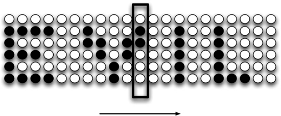
Figure 8-35 Persistence of vision
LISTING 8-1
long period = 400;
int ledPins[6][3] = {{4, 3, 2}, {7, 6, 5}, {10, 9, 8}, {13, 12, 11},
 {16, 15, 14}, {19, 18, 17}};
int n = 128;
char *message[6] = {
"000000000000000000000000000000000000000000000000000000000000000000000000000000000
   00000000000000000000000000000000770000000000000",
"111111100220000022000333300044000000000000000000555555006666666001100011000222200
   03300033000444440000000000000000770000000000000",
"110000000022000220000033000044000000077770000005500000006600000001110011000022000
   03300033004400000000000000000000770000000000000",
"111110000002202200000033000044000000077770000005555550006666600001111011000022000
   03300033000444440000000000000000770000000000000",
"110000000000222000000033000044000000000000000005500055006600000001100111000022000
   03300033000000044000000000000000770000000000000",
"111111100000020000000333300044444000000000000000555550006666666001100011000222200
   00333330004444440000000000000000770000000000000"
};
void setup()
{
 for (int led = 0; led < 6; led ++)
 {
    for (int color = 0; color < 3; color++)
    {
      pinMode(ledPins[led][color], OUTPUT);
    }
 }
}
void loop()
{
        for (int col = 0; col < n; col++)
        {
          for (int row = 0; row < 6; row++)
          {
            int color = (int)(message[5-row][col] - '0'),
            setLed(row, color);
          }
          delayMicroseconds(period);
          allOff();
          delayMicroseconds(period / 16);
        }
}
void setLed(int led, int color)
{
digitalWrite(ledPins[led][0], !(color & 1));
digitalWrite(ledPins[led][1], !(color & 2));
digitalWrite(ledPins[led][2], !(color & 4));
}
void allOff()
{
        for (int led = 0; led < 6; led ++)
  {
        for (int color = 0; color < 3; color++)
        {
           digitalWrite(ledPins[led][color], HIGH);
        }
  }
}
Next, we have the data for the message to be displayed. If you look carefully, you can see the message in the numbers rather like the film The Matrix, only not quite as cool. Each number represents a color.
The “setup” function simply initializes all the LEDs to be output pins. This function is called automatically just once, when the Arduino board starts up.
The “loop” function is called continuously and it is here that we put the code to switch between the columns. It contains two nested loops. The outer loop steps through each column in turn, then inner loop each LED. At the center of the loop, it then sets the appropriate LED color using the setLed function.
After the LEDs for each column have been displayed, it pauses for a time specified in the period variable and then turns off all the LEDs using the allOff function before pausing again for ![]() of the period. This leaves a short gap between the columns, making the display more readable.
of the period. This leaves a short gap between the columns, making the display more readable.
The setLed function sets the three colors of a particular LED on or off depending on the color number between 1 and 7. The number between 0 and 7 is a three-bit number (three binary digits). Each of these digits can be 1 or 0, which is on or off. So a number 7 in decimal is actually 111 in binary, which means that all three colors would be on, making the LED appear white.
The expression:
!(color & 2)
will evaluate to 0 if the second bit of the color number is set (green), and 2 if it is not. This may seem the wrong way around, but the LEDs are common anode, which means they turn on when the output pins are at 0V rather than at 5V.
The allOff function simply iterates over every LED pin, setting it to 5V.
Motor Controller
PWM stands for pulse width modulation, and refers to the means of controlling the amount of power delivered to a motor in this case. We use a simple PWM controller built using a 555 timer IC. We will meet the 555 timer again in Chapter 12.
PWM controls the power to a motor by lengthening or shortening pulses of power that arrive at the motor. You could imagine this as a child sitting on a swing. If you just give the child short pushes, they will not swing as high as if you give the child a longer push.
In a motor, the motor either receives full power or no power, in pulses that arrive at perhaps a thousand times per second. The motor has no time to fully stop when the power is off, so the overall effect is that the speed of the motor is controlled smoothly.
Summary
This project could be scaled up to use a bigger number of LEDs, although you would probably have to use the Arduino’s bigger brother, the Arduino Mega, as this has a lot more input/output pins on it.
If you search the Internet for “persistence of vision,” you will find many interesting ideas. People have even displayed video using this approach.
In the next chapter, we switch our attention to spying.