
CHAPTER 5
Balloon-Popping Laser Gun

CONTINUING WITH THE GUN THEME, this project will allow the Evil Genius to shoot tin cans off a wall and burst balloons with a tiny but super-powerful laser gun, essentially your stock sci-fi “ray gun” (see Figure 5-1).
Well, actually, as you might have come to expect from the Evil Genius, there is a bit of trickery going on here.
The gun itself is just a low-power laser, and if you wish, you can simply use a standard laser pointer. The clever bits are in the “can” or the “balloon popper.” Both of these have a sensor that detects the laser light and an electronic circuit that turns on a high-power transistor.
In the case of the “can,” this transistor powers an electric motor with a weight attached. The weight is swung around and hits the inside of the can causing it to jump.
The balloon popper is very similar, but this time the transistor passes a large current through a small resistor, heating it up until it is hot enough to pop the balloon attached to it. The power flowing through the resistor is likely to eventually destroy it. Fortunately, the resistors are cheap and for this project can be considered disposable.
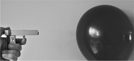
Figure 5-1 The ray gun in action
Though this is not a real gun, and is actually a low-power laser, you should still be aware of certain things:
![]() Never shine a laser into your eyes or anyone else’s.
Never shine a laser into your eyes or anyone else’s.
![]() Resist the temptation to check if the laser is on by peering into it. Always shine it onto a sheet of paper or some other light surface.
Resist the temptation to check if the laser is on by peering into it. Always shine it onto a sheet of paper or some other light surface.
![]() The balloon-popper resistor will get very hot. Plenty hot enough to burn you, so do not touch it while it is on.
The balloon-popper resistor will get very hot. Plenty hot enough to burn you, so do not touch it while it is on.
![]() Some resistor types can produce flame when used in this way, so keep the balloon popper far from anything flammable.
Some resistor types can produce flame when used in this way, so keep the balloon popper far from anything flammable.
Assembly
The project construction is split into three parts, with three separate parts lists and sets of instructions:
![]() The ray gun
The ray gun
![]() The balloon popper
The balloon popper
![]() The can jumper
The can jumper
The Ray Gun
For the “ray gun,” you can just use a laser pen, or build a more gun-like module using the following components.
What You Will Need
You can buy laser modules from standard component suppliers like Farnell and RS, but they tend to be very expensive. So look online, where they should cost no more than two or three dollars. You’ll need the parts shown in the Parts Bin.
In addition, you will also need the following tools:
![]() An electric drill and assorted drill bits
An electric drill and assorted drill bits
![]() A metal file
A metal file
![]() Epoxy resin glue or a hot glue gun
Epoxy resin glue or a hot glue gun
![]() Soldering equipment
Soldering equipment
Assembling the Gun
The first thing to say about the gun is that you don’t actually have to make it. You could just use a ready-made laser pointer. Laser pointers do not look very gun-like, so as an alternative to this design you could modify a pointer by adding a handle and trigger.
The gun (Figure 5-2) is deliberately made as small and unimpressive as possible to increase the impact of its balloon-popping and can-jumping capabilities. Figure 5-3 shows the schematic diagrams for the gun. It has only a few components and they can easily be soldered together without the need for a circuit board.
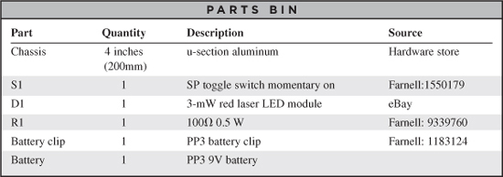


Figure 5-3 The schematic diagram for the ray gun
The components are mounted inside a u-section aluminum strip. Lengths of this can be obtained from hardware stores. The components could just as easily have been used on a strip of plastic or even built into a toy gun.
The battery clip terminals fit through holes made in the aluminum so that when a PP3 battery is attached, it forms the handle of the gun.
The resistor limits the current to the laser diode module. Resist the temptation to buy just a laser diode; instead, look for a laser diode module. The difference is that the “laser diode” will not have a lens, so you will not get the tight beam of a laser.
Step 1. Drill the Aluminum Chassis
The u-section aluminum that the author used is shown drilled and filed in Figure 5-4. Be careful to make the holes for the battery clip big enough to ensure that they will not make contact with the aluminum and cause a short circuit.
Lay out the components as they will fit onto the chassis and mark with a pencil where you need to drill. You will need a drill bit that’s the correct diameter for the toggle switch and a larger bit to make the holes for the battery clip.
After drilling, file off any burrs in the aluminum and file the holes drilled for the battery clip into a square so the clips can fit in place without the contacts touching the aluminum. Try it on for size (Figure 5-5).
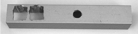
Figure 5-4 Drilling the chassis
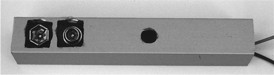
Figure 5-5 Checking that the battery clip fits
Step 2. Solder Everything Up
It is easiest to solder together all the components before fitting them into place. It also means that you can check that it works okay before you glue everything down.
Using the wiring diagram of Figure 5-6 as a guide, shorten the leads of the laser module, battery clip, and resistor to the right lengths. Strip the ends of the insulated wires and solder the components together as per the wiring diagram.
After everything is connected up, try operating the switch to make sure the laser lights up before moving on to the next step.
Step 3. Final Assembly
Fit the retaining screw over the switch and tighten it with pliers. Then, using either epoxy resin glue or a hot glue gun, glue the laser module and battery clip into place. Figure 5-7 shows the parts soldered and glued into place.
Testing the Ray Gun
The Evil Genius likes to test laser guns with the aid of a pet.
Shine the laser in front of your pet (avoid the eyes) and watch them try to catch the red spot on the floor or on the walls.
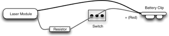
Figure 5-6 The wiring diagram for the ray gun

Figure 5-7 The assembled ray gun from above
Cats are much better for testing than dogs, because most dogs will abandon the chase once they have worked out that they cannot eat the little red dot. Cats, on the other hand, will happily chase the elusive dot around the room for some considerable time. In this respect, they are somewhat similar to minions.
The Balloon Popper
In this section, we will describe how to make the balloon-popping part of the project. If you are more interested in shooting cans than in popping balloons, skip this section.
The balloon popper (Figure 5-8) is a small box containing a battery, a light sensor, and some other electronics. When light from the ray gun hits the light sensor, it turns on a transistor that allows a large current to flow through a resistor. The resistor is fixed to a terminal block and taped to the balloon. The resistor gets hot enough to burst the balloon after 10 or 15 seconds.
The balloon popper has a control knob that sets the sensitivity of the sensor, and a switch that can be set to “live,” “off,” or “test.” When set to “test,” the resistor does not get hot; instead, an LED lights up. This lets you set the correct sensitivity.
The electronics for the balloon popper are contained in a plastic box. Most of the components are mounted onto the lid of the box. Figure 5-9 shows the schematic diagram for the balloon popper.

Figure 5-9 The schematic diagram for the balloon popper
What You Will Need
You will need the components listed in the Parts Bin for the balloon popper.
The balloon popper will eat batteries, so it is a good idea to use rechargeable cells.
In addition, you will also need the following tools:
![]() An electric drill and assorted drill bits
An electric drill and assorted drill bits
![]() Epoxy resin glue or a hot glue gun
Epoxy resin glue or a hot glue gun
![]() Soldering equipment
Soldering equipment
Step 1. Drill the Front Panel and Mount the Components
Get all the components together and lay them out next to the box so you can see where everything is going to fit. Then, mark the lid of the box where you need to drill holes for the variable resistor, phototransistor, terminal block, switch, and LED.
To fix the terminal block, make two small holes, one for each lead, and then glue the block in place (Figure 5-10).
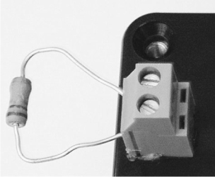
Figure 5-10 Fixing the terminal block in place


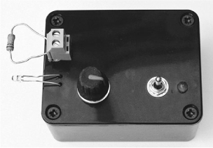
Figure 5-11 Components fitted onto the box lid
Fit the switch and variable resistor, tightening their retaining nuts with pliers. Drill a hole into which the LED will snugly fit. If it is a tight fit, it will stay in place, otherwise a drop of glue on the underside of the lid will stop it from moving.
When all the parts are attached, it will look like Figure 5-11. Notice the glue around the leads of the phototransistor to hold it in place.
Step 2. Solder the Other Components
There is no circuit board in the balloon popper. Since there are only a few components, we can simply solder the remaining components to those fixed to the box lid. Use the wiring diagram of Figure 5-12 as a guide.
The short lead of the phototransistor is the collector. This lead should be connected to the switch.
When all the components and wires are in place, you should have something that looks like Figure 5-13.
Step 3. Final Assembly
Inspect everything carefully to ensure no wires are touching. If any wires are very close to each other and may move, wrap insulating tape around them.
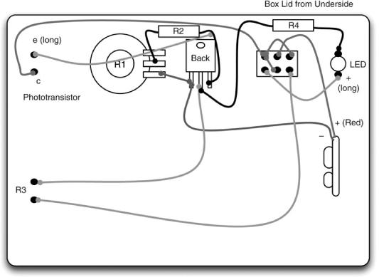
Figure 5-12 The wiring diagram for the balloon popper
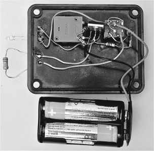
Figure 5-13 The inside of the balloon popper, with all the components in place
Before fitting everything in the box, let’s carry out a basic check on the electronics.
Fit the batteries into the battery holder; make sure the switch is in the center “off” position and attach the battery clip. Now move the switch to the “test” position (toward the LED). Next, turn the knob from one end of its travel to the other. You should see the LED turn on at some point. Set the variable resistor so the LED is on, but only just on. Then, move your hand over the phototransistor and the LED should go off.
If this does not work, go back and check your wiring, and make doubly sure that the phototransistor is the right way around.
Once everything is working, fit it all inside the box and screw down the lid (Figure 5-14).
Testing the Balloon Popper
Before we pop our first balloon, we need to check that the resistor gets hot. To do that, set the switch to “test” and turn the knob until the LED comes on. Flip the switch to “live” and hold your finger close to the resistor (don’t touch it). After a few seconds, you should feel heat coming from it. Immediately set the switch back to “off” and wait for it to cool down.

Figure 5-14 Final assembly of the balloon popper
The best way to test the balloon popper is to select the nerviest of your minions and have them stand next to the balloon popper to confirm the balloon has popped.
First attach the balloon to the resistor using Scotch tape, as shown in Figure 5-15.
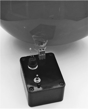
Figure 5-15 A balloon attached to the popper
Set the switch to “test” (toward the LED) and then adjust the variable resistor until the LED is just off, then turn it a little bit further so it is still off. This is adjusting the sensitivity of the sensor so it is not affected by the ambient light.
Now shine the ray gun at the balloon. When it comes within a certain range of the phototransistor, the LED should light. Practice aiming the laser at a point where the LED will light, since you will need to keep the beam on this point for ten seconds or so to pop the balloon.
When you are confident you can do this, position your minion next to the balloon (as an observer) and then flip the switch to “live.” Aim the beam at the balloon. After ten seconds or so, there should be a loud bang and a terrified minion. You should then repeat the experiment from various distances. Resist the temptation to place the balloon popper on the head of the minion, as you may end up lasering the minion’s eyes.
Can Shooter
Popping balloons is all well and good, but for added impact the Evil Genius also likes to shoot cans off the wall with his ray gun. Again, there is some deception going on here. The can is a “special” can with some electronics in it. When the beam from the laser hits the phototransistor sensor, a motor swings a weight that hits the side of the can and makes it jump. If the can is carefully balanced, the movement will be enough to make it fall off the surface it is standing on. Figure 5-16 shows the can jumper, which as you might expect just looks like a can full of the Evil Genius’ favorite lunchtime snack.
Figure 5-17 shows the schematic diagram for the can jumper.
This uses a light sensor in a similar way to the balloon popper. However, in this case, when the laser hits the phototransistor turning on the MOSFET power transistor, rather than heating a resistor, it turns on a motor that swings an arm around that hits the can.

The diode across the motor prevents the high reverse voltages you get when using a motor from destroying the MOSFET.
What You Will Need
You will need the components for the can shooter that are listed in the Parts Bin.
You do not usually get much information about a small DC motor when buying one. Often, all you get is its nominal voltage. The author found his motor in a local electronics store for a few dollars. You may also find one as part of a scrap toy or an educational motor kit.
Look for a motor about the same size as the one shown in Figure 5-21 later in the chapter. Chances are it should have a similar amount of power. A 4–6V motor should be fine even though we are going to momentarily power it from 9V. It should not have time to burn out for the small fraction of a second it is on. However, do not be tempted to buy a lower voltage than this because you may well burn it out.

Figure 5-17 The schematic diagram for the can jumper
The battery is a rechargeable 9V PP3 battery. There are good reasons for using a rechargeable battery here. The motor is likely to draw several amps, the battery will become dead quite quickly, and it is greener and more economical to recharge rather than replace.
The expanded packing material is going to be used to diffuse the light from the laser. Look for something that will allow light to pass but diffuse it like frosted glass. We also use this useful material in Chapters 7 and 10, which focus on a laser beam alarm and laser voice transmission.
In addition to these components, you will also need the following tools:
![]() An electric drill and assorted drill bits
An electric drill and assorted drill bits
![]() Epoxy resin glue or a hot glue gun
Epoxy resin glue or a hot glue gun
![]() Soldering equipment
Soldering equipment
![]() Scissors
Scissors
![]() Scotch tape
Scotch tape
Figure 5-18 shows the overall design behind the can shooter.
All the components, including the motor and battery, are mounted onto a piece of perforated prototyping board. This board is like stripboard, but without the strips of copper. It’s just a board with holes drilled into it at a pitch of 0.1 inches. It provides a useful framework to which the components can be attached.
Because the motor swings upward, gravity will take care of returning the arm to its resting position, making it ready for the next shot.
The design has a micro-switch at the top of the board so the can is turned on when the lid is put in place. Since the lid also blocks out the light to prevent the can jumper from being activated by ambient light, this works well.
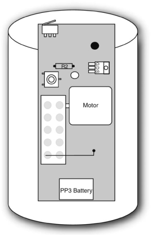
Figure 5-18 Design of the can jumper
Step 1. Cut the Perforated Board
First, find an empty one-pound (450 g) food can. The type with a ring-pull top is needed since it is structurally stronger after it has been opened and has far fewer sharp edges on which to cut yourself. The exact dimensions of cans vary, so you will need to get the length of the perforated board to make an exact fit with your can. The external dimensions of the Evil Genius’ can were 4¼" × 3" diameter (108mm with a diameter of 75mm).
Cut the perforated board with scissors so it is the right length to fill the can from top to bottom. The width is less critical, meaning the width of 1![]() inches (49mm) shown in Figure 5-19 should be fine unless you have a very unusually shaped can. The board should be a snug fit top to bottom.
inches (49mm) shown in Figure 5-19 should be fine unless you have a very unusually shaped can. The board should be a snug fit top to bottom.
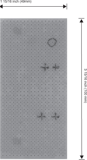
Figure 5-19 Sizing the perforated board
Step 2. Build the Arm Assembly
Electric motors usually just end in a metal shaft. The way we attach the arm to the shaft is to use a screw terminal block as our arm. We can just pop the shaft into one of the terminal connectors and tighten the screw. The terminal block strips usually come with ten or more connections in a strip. We only need five, but they can be easily cut into a section of five, using a knife.
The terminal block is reasonably heavy so as to provide some momentum to be transferred into the can. We help this along with a nail, which will also strike the screw.
The whole arrangement is shown in Figure 5-20.
One of the nails is going to be bent at right angles about half an inch (12mm) from its end. This will strike the self-tapping screw fitted at the right place on the perforated board. The screw will allow the stop point of the arm to be adjusted so it is past the tipping point and will fall back after the can has been shot.
The other terminals of the block can be used to attach more weight to the arm. There is, however, a trade-off between the amount of weight on the arm and how fast it moves. So experiment to see what suits your motor best.
Step 3. Attach the Motor
Attach the arm to the motor and position the motor halfway up the perforated board. You now need to mark where the bent nail will hit the perforated board, because we are going to make a hole there so we can fit the self-tapping screw.
Some perforated board is made of fiberglass, so wear a mask and safety goggles when drilling it because fiberglass is not a good thing to have in your lungs.
Be careful when drilling the perforated board, because it is easy to break if the drill “digs in” to one of the perforations. Choose a drill bit that is just slightly smaller than the diameter of the self-tapping screw.
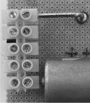
Once the screw is in place, find just the right place for the motor to fit so the nail hits it dead center. Also, put the board into the can, and make sure everything fits and that the arm has enough room for its complete travel, before gluing the motor into place (Figures 5-21 and 5-22).
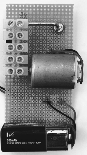
Figure 5-21 The motor attached to the board in the “up” position
Before we add the electronics, we need to test the motor to make sure everything we have done so far works. We also need to work out the polarity of the motor so we know which terminal goes to positive and which to negative.
After putting the arm in its resting position, take your 9V battery and very briefly touch the contacts to the motor contacts. If it flies up to the top position, make a note of which terminal on the motor was positive.

Figure 5-22 The motor attached to the board in the “down” position
If it just kind of twitches a bit, then try the battery the other way around.
At this point, you can also experiment with different weights on the arm to see what works best for your motor.
Step 4. Add the Electronics
We can now fit the components to the perforated board. The component leads are pushed in from the top of the board and connected together on the back of the board using the component leads and wire. Figure 5-23 shows the wiring diagram.
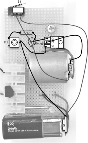
Figure 5-23 Can jumper wiring diagram
Push all of the components into place and then use Figure 5-23 as a reference to connect up the components. The front of the completed board is shown in Figure 5-24, while Figure 5-25 shows the back of the board.
Take particular care to get the phototransistor the correct way around. Check its data sheet, but the longer lead is normally the emitter and the shorter lead the collector. The collector goes to the positive 9V supply.
Glue the battery clip perpendicular to the board, as shown in Figure 5-24.
When connecting wires to the motor, make sure you connect the positive power supply to the connection you found to be positive in the test at the end of the previous section.
We can now test everything before we move onto the final stage of fitting it all into the can.
While in the can, the phototransistor will be in very low light, so we need to do this testing in fairly low light to prevent the phototransistor from being turned on all the time. We can also turn the preset variable resistor to its most clockwise position to make the sensor as insensitive as possible.
Connect everything up and put the arm in its resting place. If the motor is activated, then disconnect the battery immediately and check everything. Remember, if the motor is left on but is unable to move, it may burn out.
Now shine the laser (or any light) onto the phototransistor and the arm should fly up to the top position.
Step 5. Prepare the Can
The first thing we need to do is consume the contents of the can and clean it out thoroughly. If the can contains a food that is not to the liking of the Evil Genius (dog food, for instance), it can be fed to a minion since the Evil Genius believes it’s a crime to waste food. The can should be of the “ring-pull” type so there are no sharp edges at the top. You will need to make a hole in the can for the laser beam to enter.
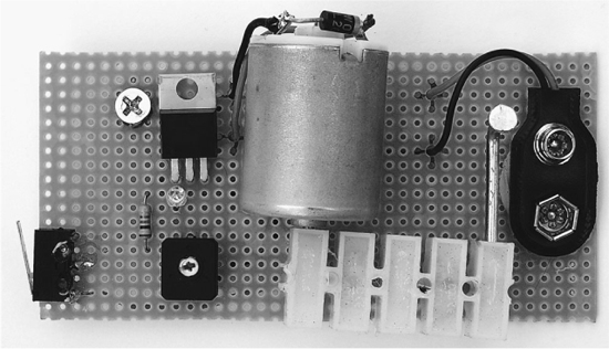
Figure 5-24 The front of the completed board
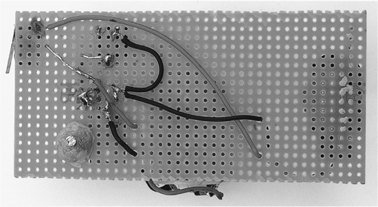
Figure 5-25 The back of the completed board
Put the board into the can and mark a position directly opposite the phototransistor. Drill a hole there about ¼ inch (6mm) in diameter. Now, tape a pad of the packing material about 1½" × 1" over the hole using Scotch tape (Figure 5-26).
Without the packing material as a diffuser, the laser would pass straight through the hole and only activate the can if a direct hit was scored on the phototransistor. With the packing material in place, the laser illuminates the material, which then lights up the entire can, triggering the phototransistor. You can see this effect in Figure 5-27.

Figure 5-26 Fitting the diffuser
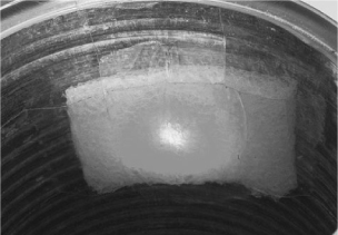
Figure 5-27 The diffuser being illuminated by the laser
Figure 5-28 shows the hole with the diffuser behind it. A hit on any part of the diffuser will trigger the can jumper. To disguise the hole, you could glue the label back on. A label with some white in the pattern would be ideal so that a hole could be cut in the label over the location of the hole on the can.
It now just remains to fit everything into the can and test the can jumper. The battery sticks out perpendicular to the board and takes up most of the width of the can. This will keep the bottom of the board in place.
The top of the board is held in place with adhesive putty (see Figure 5-29).
We now need to make the lid of the can (Figure 5-30). Using the rim of the can as a guide, trace the outline onto strong card and cut it out. If one side of the card is black, that is a bonus, but not essential. The lid needs to be a snug fit so it stays in place inside the rim of the can and holds the micro-switch in the “on” position. If the card has a black side, this should be on the inside of the lid.

Figure 5-28 The hole in the can
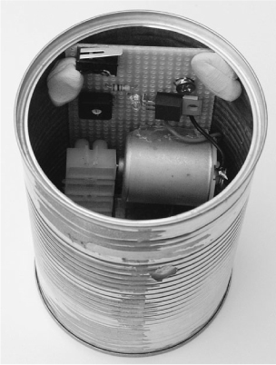
Figure 5-29 The can with the board fixed in place
Testing the Can Jumper
With just a small hole to allow ambient light in, the can is going to be quite dark inside, so you should be able to set the sensitivity to maximum. It is best to adjust the sensitivity with the board outside of the can as it is difficult to access the variable resistor when inside the can.
Maximum sensitivity means the variable resistor should be in its most counterclockwise position. So set it to that and confirm everything is okay by pressing the micro-switch. Unless you are working in the dark, the arm will fly up. Now reassemble everything and put the lid on. The can jumper may activate as you put the lid half in place, but you should hear the arm return to its resting place when the lid is fully in place and blocking out the light. If it does not return without you putting your finger over the sensor hole, you will need to take it apart again and reduce the sensitivity a bit.
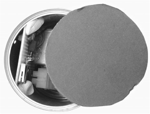
Figure 5-30 The lid to the can jumper
You are now ready to use your can jumper. You may find it amusing to place the can near one of your minions and, while out of their sight, activate the can with your laser gun. For best results, select a minion with a fear of the supernatural.
Theory
In this section, we take a look at some of the technology behind this project. In particular, we look at the two types of transistors that we use.
First, we look at MOSFET power transistors used to switch big loads like the the motor, and then we look at the phototransistor that we use to trigger the MOSFET.
MOSFETs
MOSFETs (Metal Oxide Semiconductor Field Effect Transistors) are a type of transistor that is excellent for switching high currents. When they are turned fully off, they have a huge resistance, and when they are on, they have a very low resistance. This means that they generate very little heat when used as a switch that is either fully on or fully off.
They differ from more normal “bipolar” transistors in that they are controlled by voltage rather than current. That is, it is the voltage at the “gate” connection of a MOSFET that determines whether it turns on or not. Only a tiny current flows into the gate, making them ideal for switching from low-current sources like our phototransistor.
Phototransistors
To understand what a phototransistor is, we need to know a little about how a regular bipolar transistor works.
Figure 5-31 illustrates how a regular transistor works.
This transistor has three leads: the emitter, the collector, and the base. The basic principal is that a small current flowing through the base will allow a much bigger current to flow between the collector and the emitter.
Just how much bigger the current is depends on the transistor, but it is typically a factor of 100. So a current of 10mA flowing through the base could cause up to 1A to flow through the collector and emitter. The actual current flowing will depend on the value of the load resistor. In the case of the balloon popper, this load resistor comprises a variable resistor of 100kΩ and a fixed resistor of 1kΩ. The fixed resistor limits the current when the variable resistor is set to zero.
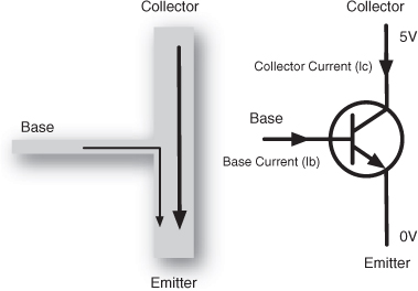
Figure 5-31 The operation of a transistor
A phototransistor is a variation on this theme. A phototransistor will often have no base connection and will be contained in a clear plastic case. Instead of a small current being supplied to the base, the current flowing through the collector and emitter is controlled by the intensity of the light falling on the phototransistor.
Summary
It is this kind of trickery that helps the Evil Genius maintain his mastery of the world. Nothing impresses the minions like the threat of instant death by ray gun.
In constructing this project, we have learned a bit about sensing light and controlling power, whether it is to the resistor used as a heating element, or to the electric motor of the can jumper.
In creating this project, an alternative design was considered for the can jumper: using a mechanical mousetrap. These hold quite a lot of energy in them, and they can be triggered by a solenoid. However, in the end, the advantages of a system using a motor that would reset itself was considered the better option. It also seemed more likely that the Evil Genius would retain more fingers by avoiding said mousetraps.
In the next chapter, we will look at adding a touch-controlled laser sight to a BB gun.