
CHAPTER 11
Flash Bomb

TIME SOMETIMES PASSES SLOWLY in the Evil Genius’ Lair. The winter months drag on with little opportunity for evil. The long dark evenings can be enlivened by inflicting pranks on the hapless minions.
The Evil Genius likes to amuse himself by leaving an interesting looking object lying around. When picked up by a passing minion, suspecting it might be something that has been misplaced by its master, it administers a bright flash into their faces.
The device uses a secret micro-switch on its base to detect when it has been picked up.
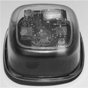
This is an easy project to make as it is built using the flash module of a single-use camera, which is then housed in a small plastic food container (Figure 11-1).
WARNING!
This project uses a bright xenon flash tube. Because of this, you should take the following precautions.
![]() When disassembling the disposable camera, be extremely careful since the flash capacitor is charged to over 300V and the trigger transformer produces voltage spikes of 4kV.
When disassembling the disposable camera, be extremely careful since the flash capacitor is charged to over 300V and the trigger transformer produces voltage spikes of 4kV.
![]() Always disconnect the battery and discharge the flash before touching the circuit board.
Always disconnect the battery and discharge the flash before touching the circuit board.
![]() Do not use this project around anyone who suffers from epilepsy.
Do not use this project around anyone who suffers from epilepsy.
![]() Do not stare into the flash tube—it is very bright at close range.
Do not stare into the flash tube—it is very bright at close range.
What You Will Need
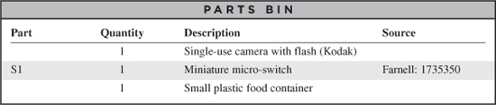
You will need the following components to build this project. They are listed in the Parts Bin on the next page.
The author used a Kodak single-use camera. If you are using a different camera, the design will differ from the following instructions, but you should still be able to adapt the design.
With the advent of digital cameras, it is becoming harder and harder to find single-use cameras. You can often obtain used camera bodies for free from film processors. If you cannot, a new one will only cost you a few dollars.
You will also need the following tools for this project:
![]() Soldering equipment
Soldering equipment
![]() A hot glue gun or self-adhesive pads
A hot glue gun or self-adhesive pads
![]() An electric drill and assorted drill bits
An electric drill and assorted drill bits
Assembly
We will remove the main circuit board of the camera and mount it in a transparent food container. The contacts normally triggered by the camera’s shutter will be replaced by a micro-switch. We use the normally closed contacts of the switch so that when the project is sitting on a table, the switch will be depressed; however, as soon as it is picked up, the contact is made and the flash fires.
The schematic diagram for the project is shown in Figure 11-2.
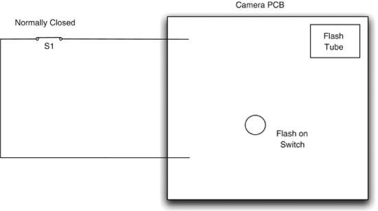
Figure 11-2 The schematic diagram for the project
Step 1. Disassemble the Disposable Camera
These disposable cameras (Figure 11-3) are remarkably complex considering their price tag of a few dollars. Little difference exists between them and a cheap film camera. In the device chosen, the flash uses a decent-sized capacitor and packs a considerable punch.
Do not take the camera apart if the flash is on. The camera will have a switch that turns it on, and when the flash is charged, a ready light will come on. The camera used by the author had a press switch that had to be held down for eight seconds to turn the flash on. If this ready light is on, its capacitor will be charged up to over 300V, just waiting to discharge itself through you. This will hurt and could cause some injury. Not only that, but many parts of the circuit board will be at high voltage even though the flash might be switched off.
So, make sure the flash is off. If you have had the flash on to try out the camera, turn it off and leave the camera alone for a few hours. Even then, use caution with the following steps until you have had a chance to discharge the capacitor.
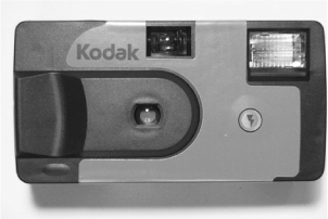
Figure 11-3 A single-use camera
If you peel back the adhesive labels over the plastic, you will find clips that hold the camera in place. Carefully unclip these, revealing the innards of the camera (Figure 11-4).
Notice the large tubular capacitor below the lens. Before you go any further, without touching anything metal, flip out the single AA battery, and using a screwdriver, short out the two leads of the capacitor. If the capacitor was charged, there will be a big bang and sparks, and your screwdriver will have scorch marks on it.
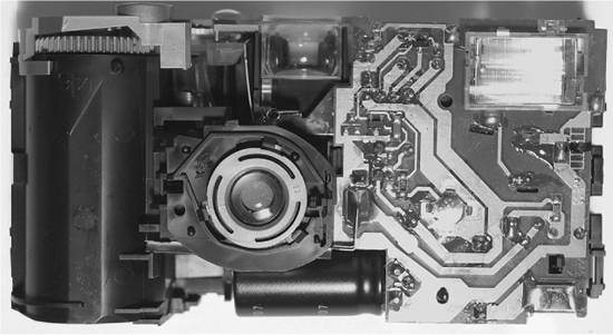
Figure 11-4 The inside of the single-use camera
However, if you have followed the instructions and only disassembled the camera when discharged, you should get no more than a little pop as the residual charge in the capacitor is discharged.
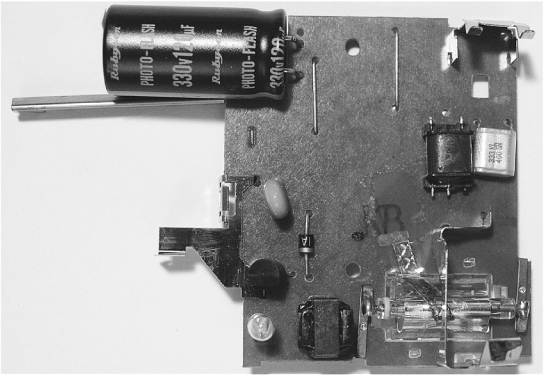
We can now carefully pull the circuit board away from the camera body (Figure 11-5).
Looking at Figure 11-5, we can see the back of the flash tube on the bottom right. Be careful not to touch the glass of the tube because it will shorten its life. On top of the flash tube is one end of the battery clip; the other end of it is shown in the top right of Figure 11-5. Note that it is not immediately obvious which is the positive connection for the battery. Actually, the top connector is the positive connector.
If you are using a different type of camera, then it is worth taking note of the battery polarity when disassembling the camera
Directly beneath the capacitor you should see a long metal contact. Directly beneath that is a second shorter contact. It is these contacts that are closed by the shutter when it opens to allow light to reach the film.
Step 2. Attach the Micro-switch
We can now cut off those large metal contacts and replace them with a micro-switch attached to a short length of twin wire. Two separate wires are fine if you do not have twin core flex available.
We need to attach our micro-switch so that the contacts are “normally closed.” That is, the connections to the switch are normally closed, but when you press the lever at the top of the switch, they open.
If you look closely at the micro-switch, its three pins will normally be labeled Common, NC (normally closed), and NO (normally open). Solder your leads to the NC and Common connections. If your micro-switch is not labeled in this way, then test it with the continuity setting on your multimeter to determine the normally closed and common connections.
When it’s all soldered together, you should have something that looks like Figure 11-6.
In the center of the circuit board, you can see a little raised area with four terminals. This is the switch that has to be held down for eight seconds to turn on the flash. You will find that when you push it with a screwdriver, it will click.
At this point, it’s a good idea to test what we have done so far, before we start fixing it into its box.
Again, exercise extreme caution, or you will get a nasty jolt. In other words, don’t touch anything metal with your fingers.
Carefully fit the battery back in. Nothing will happen immediately since the flash has not been turned on. Before you do that, hold down the lever on the micro-switch and then with the other hand (using something insulating such as plastic) press in the switch on the circuit board for eight seconds.
You should hear the charging circuit kick into action and after a few seconds the indicator light will glow.
At this point, if you release the micro-switch, you will get a flash.
Before moving onto the next step, we need to make sure the capacitor is discharged. The best way to do this is to, without touching the circuit board, take the battery out, and then discharge the flash by pressing and releasing the micro-switch again so the capacitor is discharged through the flash tube.
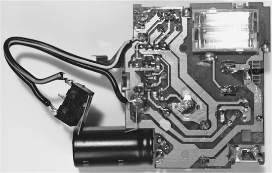
Figure 11-6 The micro-switch attached to the PCB
Step 3. Box the Project
As you can see from Figure 11-1 earlier, the PCB is simply glued to the bottom of the plastic food container using a hot glue gun. But before doing that, we need to drill a small hole opposite the push switch that turns the flash on. We will then be able to poke a toothpick in it to turn the device on.
The glue will stick better if the plastic container is roughened with sandpaper.
Figure 11-7 shows the open box with the PCB glued inside.
The micro-switch is fitted into the lid of the box by cutting a slit in the lid, pushing the switch through, and then fixing it in place with the hot glue gun (Figure 11-8).
We can now test the project by putting a toothpick through the hole to turn the flash on while holding down the micro-switch. When the indicator light comes on, we release the switch and it should flash.
Using the Project
For best results, leave the project lying around somewhere slightly out of place, where someone is likely to pick it up and look at it.

Figure 11-7 The PCB fitted inside the box
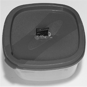
Figure 11-8 The micro-switch attached to the box lid
Theory
Modding the single-use camera in this way has saved us the trouble of designing the electronics from scratch. However, it’s always interesting to know how these things work, and this camera is a masterpiece of simple (and cheap) design.
Flash Guns
A flash gun works much like the coil gun we built in Chapter 1. In both cases, we charge up capacitors over a period of time and then discharge them in a very short time. In the case of the coil gun, we discharge it through a hefty coil, but in this case we discharge it through a xenon flash tube.
Figure 11-9 shows a logical diagram of the flash circuit.
Another difference with the coil gun is that the coil gun operated at around 40V (using four 9V batteries), whereas the flashgun operates at about 330V, using just a single 1.5V battery.
This is only possible because the flashgun contains a circuit to increase the 1.5V from the battery to 330V. It does this using an oscillator that drives a transformer.

Figure 11-9 Logical diagram for the flash gun
The high voltage is then rectified by a diode and charges the capacitor. Even when the capacitor is fully charged to 330V, the flash tube will not fire until a much higher trigger voltage pulse of around 4kV is applied to the trigger connection of the tube. This pulse is generated by a special high-voltage trigger transformer. The trigger transformer receives a short pulse when the shutter is released.
Summary
This is a nice easy project and one intended for mischief. However, please be careful, both of the high-voltage electronics and in using it responsibly.
In the next chapter, we stay with the flashing theme and develop a project that uses 36 high-brightness LEDs to make a strobe light.