
CHAPTER 4
Mini Laser Turret

WHEN PLANNING A CAMPAIGN of world domination, the Evil Genius likes to set up a model battlefield using small plastic warriors on a realistic but miniature battleground. Such preparations are made even more enjoyable if one of the Evil Genius’ favorite toys is brought into play.
The mini laser turret (Figure 4-1) can sit amidst the miniature battlefield. A joystick allows the laser to be directed in a sweeping arc across the battlefield, cutting a deep swath through the massed ranks of the enemy.

The turret gun is made of two miniature servos, of the type used in remote control planes, mounted at right angles to each other so that one sweeps left to right and the other raises or lowers the laser module. Wires connect the turret to a control unit with a homemade joystick that allows the laser to be aimed remotely.
This project can also be combined with the project in the next chapter to allow the popping of balloons or the jumping of a can by the laser.
WARNING!
You should always take certain precautions when using lasers:
![]() Never shine a laser into your eyes or anyone else’s.
Never shine a laser into your eyes or anyone else’s.
![]() Resist the temptation to check if the laser is on by peering into it. Always shine it onto a sheet of paper or some other light surface instead.
Resist the temptation to check if the laser is on by peering into it. Always shine it onto a sheet of paper or some other light surface instead.
What You Will Need
To build this project, you will need the components shown in the Parts Bin on the next page.
You can buy laser modules from standard component suppliers like Farnell and RS, but they tend to be very expensive. So look online, where they should cost no more than two or three dollars. The same applies to the servo motors, and if you are happy to wait a week or two for your parts to come from China, there are some bargains to be had this way, too.

In addition, you will also need the following tools:
![]() An electric drill and assorted drill bits
An electric drill and assorted drill bits
![]() Soldering equipment
Soldering equipment
![]() Epoxy resin glue or a hot glue gun
Epoxy resin glue or a hot glue gun
![]() A craft knife
A craft knife
Figure 4-2 shows the schematic diagram for this project.
The circuit is based around a dual timer chip, one for each of the servo motors. This is described more fully in the “Theory” section at the end of this chapter.
Assembly
The following step-by-step instructions walk you through making the laser turret. First, we construct the joystick, then the laser and servo assembly, and then the electronics that link it all together.
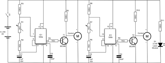
Figure 4-2 The schematic diagram for the mini laser turret
Step 1. Make a Frame for the Joystick
The construction of the joystick is shown in Figure 4-3. The two variable resistors are fixed to each other at the flat part of the stems by drilling a small hole through them and then fixing a nut and bolt through the two. The handle is cut from the same plastic, a hole drilled in it, and then mounted on one of the variable resistors.

Figure 4-3 Construction of the joystick
The frame for the joystick is made from a rightangle plastic molding, cut to shape with scissors (Figure 4-4). Any suitable plastic of reasonable thickness is fine for this. The handle for the joystick is made from the same material (Figure 4-5). Both pieces are drilled to fit the variable resistor.

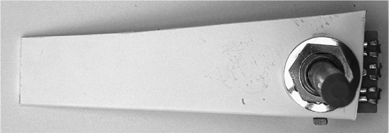
Figure 4-5 The joystick handle
Step 2. Fix the Variable Resistors Together
After cutting and drilling the plastic for the frame and handle, fit the variable resistors and then join them together through the drilled holes (Figure 4-6).
Step 3. Finish the Joystick
Solder 4-inch (100mm) leads to the center and right connections (looking from the back of the variable resistor) of each variable resistor. These will be attached to the stripboard when we have completed it.

Figure 4-6 The variable resistors attached to each other
Step 4. Fix the Laser and Servos
Figure 4-7 shows the design and wiring of the turret module. The laser module is mounted onto one of the servos. This servo is then mounted onto the arm of the other servo so the bottom servo will control the vertical angle of the laser, and the top servo the horizontal angle.
The servos are usually supplied with a range of “arms” that push onto a cogged drive and are secured by a retaining screw. One of the servos is glued onto one of these “arms” (Figure 4-8). Then, the arm is attached to the servo. Do not fit the retaining screw yet, since you will need to adjust the angle. Glue the laser diode to a second “arm” and attach that to the servo. It is a good idea to fix some of the wire from the laser to the arm in order to prevent any strain on the wire where it emerges from the laser. You can do this by putting a loop of solid core wire through two holes in the server arm and twisting it around the lead (again, see Figure 4-8).
Next, cut a slot in the can lid so the servo arm can move (Figure 4-8). Afterward, glue the bottom servo to the lid. Make sure you understand how the servo will move before you glue it.
Once you are sure everything is in the right place, fit the retaining screws onto the servo arms. You may need to adjust these once you come to test the project.
Step 5. Wire the Servos and Laser
The wires from the servos and the laser module will all be connected up to a terminal block (Figure 4-9). You will need to shorten the leads, and it is much easier to fit them into the terminal blocks if you solder the leads together first.
The colors of the leads on the servo vary among manufacturers. The leads on the author’s servos were brown for GND, red for +V, and orange for the control signal. Check the datasheet for your servos to make sure you have the right leads.
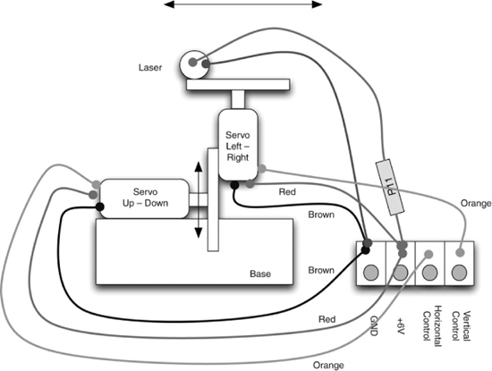
Figure 4-7 The design of the turret module


Figure 4-9 The turret module showing the wiring
Using Figure 4-7 as a reference, wire up the turret.
All the negative leads from both servos and the laser module go into the left-hand terminal block. The next terminal block has the positive leads of the servos and the 100Ω resistor. The resistor leads should be shortened and the positive lead of the laser module connected to the end of the resistor.
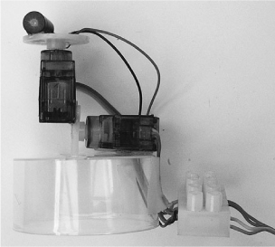
Figure 4-10 The completed turret module
The final two connections for the terminal block are the control signals from the servos.
Figure 4-10 shows the completed laser turret module, with the ribbon cable attached and ready to be connected to the stripboard.
Step 6. Prepare the Stripboard
Figure 4-11 shows the stripboard layout for the project. Note that it is shown as viewed from above.
Begin by cutting the stripboard to size: we need 15 strips, each with 20 holes. A strong pair of scissors can do this just fine. Using a drill bit, and twisting it between your fingers, cut the track in the locations marked with an “X.” Figure 4-12 shows the back of the board, ready for soldering.
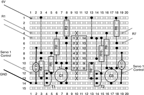
Figure 4-11 The stripboard layout
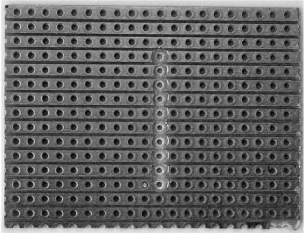
Figure 4-12 The prepared stripboard
Step 7. Solder the Components
First solder in the linking wires. Use solid core wire, either by stripping normal insulated wire, or by using previously snipped component leads. When all the linking wires are in place, the top of the board should look like Figure 4-13, and the bottom of the board like Figure 4-14.
The trick with the stripboard is to solder the components that rise least from the board first. That way, when you put the board on its back, they are held in place by the board while you solder them. This being the case, we are going to solder the resistors next.

Figure 4-13 The top of the stripboard with the linking wires in place

Figure 4-14 The bottom of the stripboard with the linking wires in place
Figure 4-15 shows the board with the resistors in place.
We can now solder the timer chip. You may choose to use an IC socket rather than solder the chip directly onto the board. If you do decide to solder the chip directly, be very careful to put it the right way around and in the right place. Once soldered into place, it is very hard to remove the chip. Also, be careful not to overheat the chip while soldering. Try to do it quickly, pausing a few seconds after soldering each pin.
After the chip (or socket), solder the small capacitors (C2 and C4) and the transistor. Again, check that the transistors are the right way around. Finally, we can solder the large capacitors (C1 and C3) into place, making sure the polarity is correct. The negative lead is the shorter of the two leads and often has a diamond next to it.

Figure 4-15 The top of the stripboard with the resistors in place
The completed board is shown in Figures 4-16 and 4-17.
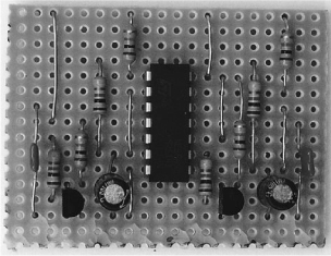
Figure 4-16 The completed stripboard from the top
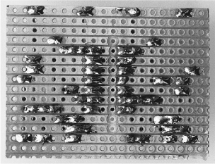
Figure 4-17 The completed stripboard from the bottom
Step 8. Wire Everything Together
Having built the turret module joystick and stripboard, it is now time to wire everything together. Figure 4-18 shows the wiring diagram of the project.
Using Figure 4-18 as a guide, wire together all the components. The ribbon cable to the servo module is fine for a length of a few feet, but you may run into trouble if you try and attach a long cable. Eventually, the pulse width signal will become distorted and the servos will behave unpredictably. Alternatively, to get a longer range with your wires, use multi-core shielded cable, where each of the control signals is in its own screened cable.
So, now that everything is connected, perform a final check to make sure there are no bridges of solder on the stripboard and that all the wires are in the right place. Afterward, insert the batteries and turn it on. The servos should “snap” to the position of the joystick.
If nothing happens, or only one of the servos works, disconnect immediately and check everything over.
Step 9. Adjust the Servo Arms
At this stage, you will probably need to adjust the position of the servo arms.
With the project turned on, set the joystick to its center position. Remove the two server arms and refit them so the servo is pointing the laser straight ahead, both horizontally and vertically.
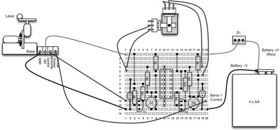
Figure 4-18 The wiring diagram
Step 10. Fit the Project into a Box
Because the joystick has quite a wide range, this is a difficult project to box. However, fitting the battery, the stripboard, switch, and joystick into a box without a lid will at least neaten up the project and provide a firm base for the joystick (Figure 4-19).
A hole is drilled for the switch, and another for the cable to the servo turret. The joystick frame is glued to one side of the box. The adventurous Evil Genius may even decide to provide a lid for the box.
Ideas
The Evil Genius might like to make more than one turret connected to the same joystick. That way, when the joystick is moved, all the turrets move. This is very easy to do. Each turret servo assembly is essentially connected in parallel, as shown Figure 4-20.
Theory
When it comes to making things move, servo motors are great. They are easy to use, quite low power, and only require one wire to control their position. In this section we learn a little more about how to use Servo motors.
We also take a look at the 555 timer IC, which is used to generate the pulses for the project. This timer chip is extremely versatile and it is useful to know how to use it.
Servo Motors
Servo motors are most commonly used in radio-controlled model vehicles.
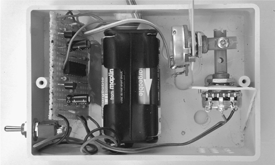
Figure 4-19 Boxing the project

Figure 4-20 Controlling more than one turret from a joystick
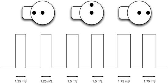
Unlike standard motors, a servo module does not rotate around and around. It can only travel through about 180 degrees. The modules are controlled by pulses of voltage on the control connection to the servo. The length of the pulse controls the angle to which the servo is set.
Figure 4-21 shows an example waveform. You can see how the width of the pulses varies the servo angle.
A pulse of 1.5 milliseconds sets the servo to its center position, a shorter pulse of 1.25 milliseconds to its leftmost position, and 1.75 to its rightmost position.
The servo motor expects there to be a pulse at least every 20 milliseconds for the servo to hold its position.
The 555 and 556 Timer ICs
To generate the pulses for our servo, we use a timer chip. Actually, the chip contains two timers in one package. That is, one for each servo.
The chip is an NE556, which contains the equivalent of two NE555 chips, one of the bestselling chips ever created. This chip has been around since 1971 and sells around a billion units a year. It can be used as both a one-shot monostable that produces just a single pulse, or as an astable oscillator that produces a stream of pulses.
We use it in this astable mode. The overall frequency and duration of the pulses are controlled by the timing components, comprised of a capacitor and two resistors. Figure 4-22 shows the basic arrangement on which our design is based.
Using this arrangement, as we said before, the circuit will oscillate, producing a waveform similar to that shown in Figure 4-23.

Figure 4-22 The basic 555 timer schematic

Figure 4-23 The 555 timer waveform
The “high period” shown in Figure 4-23 can be calculated using the formula:
0.69 * (R1 + R2) * C
where R is in Ω, and C is in F. A 1F capacitor is actually a huge capacitance. Capacitance values are usually measured in μF (microfarads) or even smaller units.
The “low period” shown in Figure 4-23 uses the formula:
0.69 * R2 * C
Notice that the low period only depends on the value of R2; R1 has no effect on it. This means that we can change the value of R2 to vary the length of the pulse. In our circuit, we use a combination of a variable resistor and a fixed resistor as an equivalent to R2, the total resistance being the sum of the variable resistor and the fixed resistor. The overall frequency will vary, but for servo motors, it’s the length of the pulses that matter, not the overall frequency.
This system has one snag: We can easily vary the low period, but the servo motor is controlled by the high period. This is why we use a transistor connected to the output signal. This transistor inverts the signal, converting the high into low, and vice versa.
Summary
In this project, we learned how to make a joystick from a pair of variable resistors, as well as how to use servo motors. We also explored the extremely versatile 555 timer IC.
As an alternative to controlling the servos using a joystick, we could also control them with an Arduino interface board. We will use these small microcontroller boards in Chapters 8, 13, and 15. If you are interested in computerizing your servos and laser, there is a design in the book 30 Arduino Projects for the Evil Genius by this author (Simon Monk) that does exactly that.