
CHAPTER 15
Surveillance Robot

THE EVIL GENIUS’ LAIR IS PATROLLED by a security robot. This robot (Figure 15-1) wanders around the lair in a random manner, occasionally tripping up minions. It also serves the more practical but less amusing role of monitoring the lair when the Evil Genius is asleep at night.
The robot is equipped with a passive infrared sensor and a loud alarm. It will move around, occasionally stopping and monitoring the area in front of it with its PIR movement sensor. If it then detects any movement, it sounds the alarm.
This is another project based on an Arduino microcontroller board. It uses modified low-cost electric screwdrivers to provide powerful geared motors to drive it along, and an infrared distance sensor to prevent collisions (although this is not always successful).

Figure 15-1 Surveillance robot
If you want to learn a bit more about robotics, this project provides an excellent starting point, and you can extend the project in several ways—for example, by adding a wireless camera and remote control.
Assembly
This is a complex project, so to simplify matters we are going to divide it up into a number of modules, each of which can be assembled and tested separately. The overall arrangement of the modules is shown in Figure 15-2.
You can see that we are going to use two batteries: one 9V PP3 battery to power the Arduino and other components such as the PIR sensor that require 9V, and a second battery comprised of six rechargeable AA batteries in a battery holder. This battery supplies the power to the electric motors.
We will start by building the motor controllers, and then build the rest of the electronics into and onto a project box.

Figure 15-2 Schematic diagram for the surveillance robot
Assembling the Motor Drivers
These motor drivers are useful little modules that you may well find you can use in other projects. They are easy to construct and do not require many components.
What You Will Need
You will need the components that are listed in the Parts Bin to build each motor controller. Since we need two controllers, the quantities have been doubled. You will also need the six AA batteries, the holder, and the clip to be able to test the controller.
You will also need the following tools:
![]() Soldering equipment
Soldering equipment
![]() A 6V motor or Rtest (see component list)
A 6V motor or Rtest (see component list)
![]() A multimeter
A multimeter
The schematic diagram for the motor controller is shown in Figure 15-3.
The design uses an arrangement of two MOSFET transistors so the motor can be powered in either direction, depending on the control pins A and B. For a description of motor control designs, see the “Theory” section at the end of this chapter.
Step 1. Prepare the Stripboard
Figure 15-4 shows the stripboard layout for one of the motor driver modules.
The first step is to cut a piece of stripboard that has 12 strips, each with 12 holes. Two breaks must be made in the tracks. Make these using a drill bit as a hand tool, rotating it between your finger and thumb. Figure 15-5 shows the prepared board ready for the components to be soldered to it.

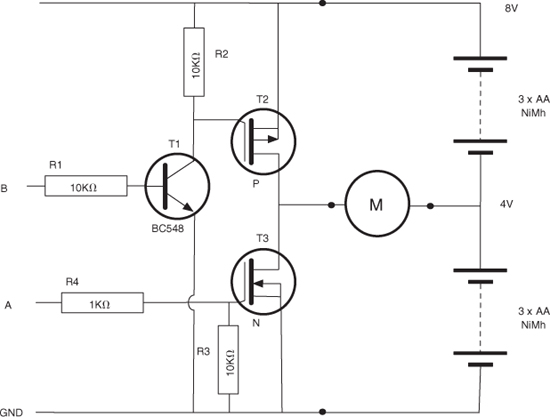
Figure 15-3 Schematic diagram for the motor controller
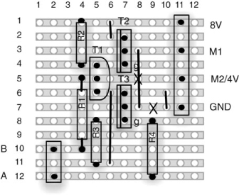
Figure 15-4 The stripboard layout for a motor driver module
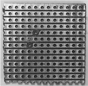
Figure 15-5 A motor driver module stripboard ready for soldering
Step 2. Solder the Links and Resistors
Before starting on the real components, solder the four wire links into place. When this is complete, your board should look like Figure 9-6.
We can now solder all the resistors in place. Once done, your board will look like Figure 15-6.
Step 3. Solder the Remaining Components
Since the terminal blocks are slightly lower in profile than the transistors and capacitor, solder them into place next.
Place the transistors into position, ensuring they are the correct way around and that the P-channel transistor is at the top of the board. Then, solder each transistor into place.
When all the components are soldered, the board should look like Figure 15-7.
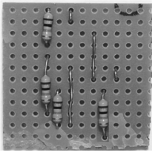
Figure 15-6 The board with resistors and links

Figure 15-7 The board with all components in place
Step 4. Test the Motor Controller Module
To test the motor controller, set up the arrangement shown in Figure 15-8. You will need to attach a lead to the 4V point in the battery holder. See Step 9 of the next section if you are not sure how to do this. You can either use the motor and see it rotate both one way and the other, or use the test resistor and just measure the voltage across it.
The lead connected to +8V will momentarily touch the screw of either A or B, but never both at the same time.
Initially, make sure there are no connections to either A or B. This will ensure that both transistors are turned off.
Touch the loose lead from + V to A, causing the motor to turn one way. The meter should read –4V. Touch it to B and it should read +4V.
The effect of the control pins A and B are summarized in Table 15-1.
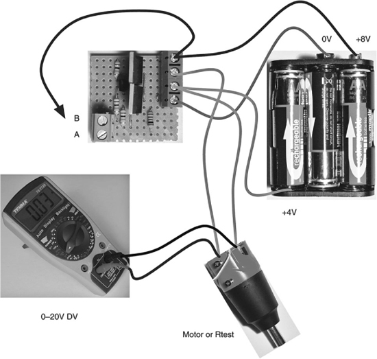
Figure 15-8 Testing a motor controller module
TABLE 15-1 Results of Pin A and B
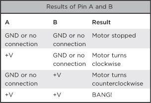
The “BANG!” condition is both interesting and important. What it signifies is that if both A and B are connected to +V at the same time, then both MOSFET transistors will be on at the same time, meaning there is effectively a short circuit between 8V and ground. This will result in very large currents flowing through the transistors, which will probably result in smoke and destruction.
This is something we must keep at the fore of our thinking when it comes time to write the software for the Arduino.
So now we have a working motor controller. But we need two, so repeat this whole process again.
Assembling It All
Now that we have a pair of working motor controllers, we need to move on to assemble the rest of the robot.
Figure 15-9 shows the wiring diagram for the project.
What You Will Need
This section assumes we already have two assembled motor controllers. The other components we need for the rest of the project are listed in the following Parts Bin.
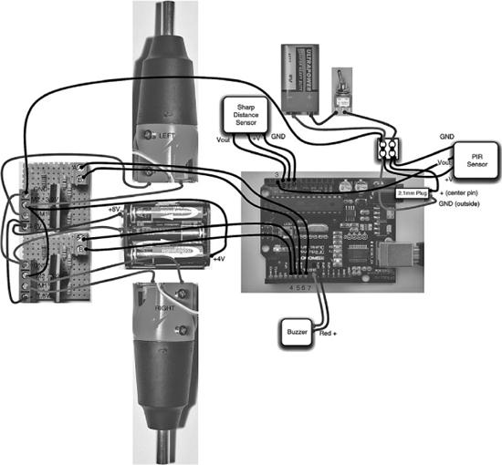
Figure 15-9 Wiring diagram for the project
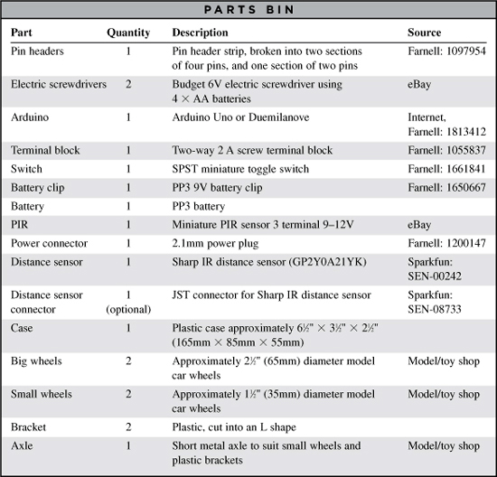
An older Arduino Duemilanove is absolutely fine for this project. However, if you want to use the latest kit, get an Arduino Uno. In either case, clones of the open-source hardware are available for considerably less money than original Arduino boards.
The screwdrivers should be of the type that takes four AA cells. The author found these available for around $8 each, made by Duratool.
The wheels were sourced from a toy shop.
You will also need the following tools:
![]() An electric drill and assorted drill bits
An electric drill and assorted drill bits
![]() A hacksaw
A hacksaw
![]() A hot glue gun or epoxy glue
A hot glue gun or epoxy glue
![]() Assorted self-tapping screws
Assorted self-tapping screws
![]() A computer to program the Arduino
A computer to program the Arduino
![]() A USB-type A-to-B lead (as used for printers)
A USB-type A-to-B lead (as used for printers)
Step 1. Disassemble the Screwdrivers
The first step is to remove the switch and battery holder end of the screwdrivers, since all we are really interested in is the motor and gearing. Figure 15-10 shows one of the screwdrivers with the battery case sawn off.
To find the right place to saw, remove the endcap and battery holder. Then, saw where you think they would end were they in the case. If in doubt, saw off less rather than more. You can always saw more off in another cut.
You need to expose the terminals to the motor. Once exposed, solder leads two or three inches in length to the terminals.
Step 2. Make the Large Wheels
One of the nice things about using electric screwdrivers is that we can use the screwdriver bits that they come with to attach the wheels. The screwdriver that the author used was magnetic, so the screwdriver bits could be glued to the big wheel and then the wheels could be attached to the screwdriver as if they were bits (Figure 15-11).

Step 3. Fix the Motors to the Case
The motors are fixed to the bottom of the case using self-tapping screws from the inside of the case, which are then fitted into the body of the screwdriver. Be careful to select screws that are long enough to go into the screwdriver casing without sticking into anything vital, like the motor casing.

Figure 15-10 Sawn-off screwdriver
Figures 15-12 and 15-13 show the screwdrivers attached from the inside and the outside. Note also the extra holes to allow the leads from the motors to enter the project box.
Step 4. Attach the Small Wheels
The two front wheel brackets are made by bending strips of plastic salvaged from packing material. They are then drilled at the end of the long end to take the axle, and at the short end to take self-tapping screws to attach them to the bottom of the project box.
Figure 15-14 shows the wheels attached to the box.
The front wheels actually do very little besides stopping the robot from falling over. Do not worry if they will not turn easily; when the robot is rotating on the back wheels, they will be traveling sideways.
For this reason, it’s actually a good idea for the front wheels to be smooth and not have a good grip.
Step 5. Attach the PIR Sensor
The PIR sensor (Figure 15-15) is designed for use in intruder alarms. The unit has three pins: +V, GND, and Vout. They are designed to work at 12V, but most will work with a supply of 9V. In this unit, the output was normally at 0V, but when movement was detected, the output rose to around 3V for about a second.
To test your PIR sensor, temporarily attach the battery clip and PP3 to the GND and +V screw terminals on the PIR sensor, then use a multimeter to measure Vout for the resting case and when you wave your hand in front of it. Chances are your sensor will behave the same; however, it may produce a different output when detecting movement. If this is the case, you will have to alter the script, in particular, the variable pirThreshold. The unit of this variable is roughly the voltage * 200. So a value of 500 means that the alarm will be triggered if the voltage goes over 500/200 or 2.5V.

Figure 15-12 The electric screwdriver motors—from the inside
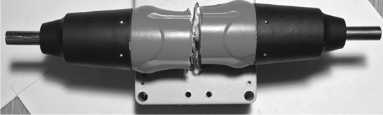
Figure 15-13 The electric screwdriver motors—from the outside
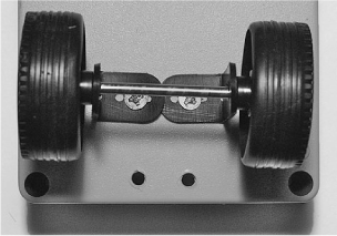
Figure 15-14 Attaching the front wheels to the box
Attach three wires to the PIR sensor terminals and thread them through a hole in the lid of the box, then glue the sensor to the box, facing forward (Figure 15-16).
Step 6. Attach the Buzzer
The buzzer used had red and black trailing leads for its positive and negative connections. It is attached in a similar way to the PIR sensor with a small blob of glue, and the leads are fed through a hole in the lid (Figure 15-16)
Step 7. Attach the Proximity Sensor
The IR proximity detector (Figure 15-17) is a clever little device that uses reflected IR light to determine its distance from any obstacle. It will measure objects ranging from 100 to 800mm.

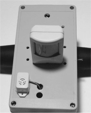
Figure 15-16 The PIR sensor and buzzer attached to the box lid
Rather like the PIR sensor, the sensor has three pins: GND, 5V, and Vout. Vout is an analog voltage that is related to the distance to the sensed object. We only care if we are going to bump into something, so all we need to know is that if the voltage at Vout rises above 2V, then we are within 120mm of hitting something, and we need to stop.
The IR sensor is attached to the front of the project box using two small self-tapping screws.
Step 8. Attach Pin Headers to the Ribbon Cable
To make connections to the Arduino, we use pin headers and short lengths of ribbon cable scavenged from an IDE hard disk cable.
Using Figure 15-9 as a reference:
![]() Solder the two-way header pin to the end of the buzzer leads.
Solder the two-way header pin to the end of the buzzer leads.
![]() Solder the three leads from the distance sensor to three of the leads from one of the four-way headers.
Solder the three leads from the distance sensor to three of the leads from one of the four-way headers.
![]() Solder the Vout lead from the PIR sensor to the remaining free pin of the four-way header used for the distance sensor.
Solder the Vout lead from the PIR sensor to the remaining free pin of the four-way header used for the distance sensor.
![]() Solder four leads to link both motor controllers’ control pins A and B to the other four-way header.
Solder four leads to link both motor controllers’ control pins A and B to the other four-way header.
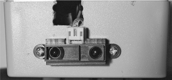
Figure 15-17 IR proximity sensor
Step 9. The Switch and Batteries
Still referring to Figure 15-9, cut the red lead on one of the battery clips and solder the switch to one side of it. The black negative lead of the battery clip and the lead from the other side of the switch are connected to one side of the two-way terminal block. Attach leads to the 2.1mm power connector and fit the leads into the other side of the terminal block, each accompanied by one of the GND and V+ connections to the PIR sensor. The 2.1mm plug can then fit into the Arduino.
Note, that we only switch the power to the 9V battery. The motor controllers will effectively keep the six-cell motor battery disconnected.
The battery for the motors needs the normal V+ and GND supplied by a second battery clip, but also requires a center supply. We will place a wire under one of the sprung connections and then use the battery to hold it in place.
Figure 15-18 shows the motor battery with the extra lead attached.

Figure 15-18 The motor battery
To find the right place, we are going to use a multimeter. The procedure is to first measure the full voltage across the connectors for the battery clip. This will probably be a touch under 8V. Leave the negative test lead connected to the battery negative and work your way around the connectors for the cells until you find a sprung one at about 4V. You can then tuck a wire into the sprung connector.
We can now wire up the leads from the motor to the terminal blocks on the motor controller, as well as the other connections from the motor controllers to the battery and GND from the other battery.
Finally, we can plug the headers into the Arduino board. Make sure they are the correct way around.
Do not plug the motor controller connector into the Arduino board until after the board is programmed, as you do not know the state of the output pins, and there may be the possibility of A and B both being high at the same time for one of the motor controllers.
Many connections need to be made here, so it may be worth checking each connection on Figure 15-9 as it is made to make sure you don’t miss one.
Step 10. Program the Arduino
Our robot is not going to do much until we program it. If you have not read about the projects in Chapters 8 and 13, which also use an Arduino, I strongly recommend you read the relevant parts of Chapter 8. This gives some background on the Arduino and explains how to install and set up your computer with the Arduino software.
The sketch (program) for the robot can be found at www.dangerouslymad.com. Paste it into a new Arduino project and upload it to the Arduino board using the instructions in Chapter 8.
Step 11. Testing the Robot
Set it down in the middle of the room and turn it on. It will start in its monitoring mode, so if you move in front of it, it should detect you and sound the alarm. After a while, it should rotate in a random direction and set off for its new position.
If it finds itself on a collision course, it will back up a little before going back into monitoring mode.
You may find that your motor connections are the wrong way around and have to swap over a few leads. If your robot is behaving erratically, you can find a helpful test sketch on this at www.dangerouslymad.com. It lets you send commands using the Serial Monitor to move forward, back, left, and right, as well as report the values from the sensors.
Theory
In this section, we take a detailed look at the code for the robot, the distance sensor and also look at techniques for controlling motors.
The Program
The sketch (Arduino parlance for a program) is shown in Listing 15-1.
The program makes a great starting point for anyone wishing to develop robots using the Arduino.
At the top of the file, we define the various pins to be used. The two variables—proxThreshold and pirThreshold—set the value that must be exceeded to indicate an imminent collision or detection of movement, respectively, using the outputs of these two sensors connected to analog inputs of the Arduino.
LISTING 15-1
// Surveillance Bot


#define HALT 0
#define CLOCKWISE 1
#define COUNTER_CLOCKWISE 2


int leftAPin = 7;
int leftBPin = 6;
int rightAPin = 5;
int rightBPin = 4;


int posPin = 14;
int negPin = 15;
int proxPin = 2;
int pirPin = 3;
int buzzPlusPin = 9;
int buzzMinusPin = 8;


float proxThreshold = 500;
float alpha = 0.5;
int pirThreshold = 10;
int monitorDuration = 120; // seconds
int alarmDuration = 10; // seconds


void setup()
{
 pinMode(leftAPin, OUTPUT);
 pinMode(leftBPin, OUTPUT);
 pinMode(rightAPin, OUTPUT);
 pinMode(rightBPin, OUTPUT);
 pinMode(pirPin, INPUT);


 digitalWrite(leftAPin, LOW);
 digitalWrite(leftBPin, LOW);
 digitalWrite(rightAPin, LOW);
 digitalWrite(rightBPin, LOW);


 pinMode(posPin, OUTPUT);
 pinMode(negPin, OUTPUT);
 pinMode(buzzPlusPin, OUTPUT);
 pinMode(buzzMinusPin, OUTPUT);
 digitalWrite(posPin, HIGH);
 digitalWrite(negPin, LOW);
 Serial.begin(9600);
}


void loop()
{
  monitor();
  moveToNewPlace();
  delay(1000);
}


void monitor()
{
  int alarmTimeout = 0;
  for (int i = 1; i < monitorDuration;
    i++)
  {
      int pirValue =
    analogRead(pirPin);
      if (pirValue > 10)
      {
         digitalWrite(buzzPlusPin, HIGH);
         alarmTimeout = alarmDuration;
      }
      if (alarmTimeout <= 0)
      {
        digitalWrite(buzzPlusPin, LOW);
      }
      alarmTimeout –;
      delay(1000);
  }
}


void moveToNewPlace()
{
  turnInRandomDirection();
  forwardOrProximity(1500);
}


void turnInRandomDirection()
{
    int duration = random(100, 3000);
    left();
    delay(duration);
    halt();
}


void forwardOrProximity(int duration)
{
  int x = 0;
  forward();
  static float lastProx = 0;
  float prox = 0;
  while (x < duration)
  {
     int rawProx = analogRead(proxPin);
     prox = alpha * rawProx + (1 -
      alpha) * lastProx;
     Serial.print(rawProx);
    Serial.print(" ");
    Serial.print(lastProx);
    Serial.print(" ");
    Serial.println(prox);
     lastProx = prox;
     if (prox > proxThreshold)
     {
       halt();
       buzz(50); buzz(50);
       delay(100);
       back();
       delay(700);
       halt();
       return;
     }
     x += 10;
     delay(10);
  }
}


void forward()
{
 setLeft(CLOCKWISE);
 setRight(CLOCKWISE);
}


void back()
{
 setLeft(COUNTER_CLOCKWISE);
 setRight(COUNTER_CLOCKWISE);
}


void left()
{
 setLeft(CLOCKWISE);
 setRight(COUNTER_CLOCKWISE);
}


void right()
{
 setLeft(COUNTER_CLOCKWISE);
 setRight(CLOCKWISE);
}


void halt()
{
 setLeft(HALT);
 setRight(HALT);
}


void setLeft(int rotation)
{
 if (rotation == HALT)
 {
   digitalWrite(leftAPin, LOW);
   digitalWrite(leftBPin, LOW);
 }
 else if (rotation == CLOCKWISE)
 {
   digitalWrite(leftAPin, HIGH);
   digitalWrite(leftBPin, LOW);
 }
 else if (rotation ==
   COUNTER_CLOCKWISE)
 {
   digitalWrite(leftAPin, LOW);
   digitalWrite(leftBPin, HIGH);
 }
}


void setRight(int rotation)
{
 if (rotation == HALT)
 {
   digitalWrite(rightAPin, LOW);
   digitalWrite(rightBPin, LOW);
 }
 else if (rotation == CLOCKWISE)
 {
   digitalWrite(rightAPin, HIGH);
   digitalWrite(rightBPin, LOW);
 }
 else if (rotation ==
   COUNTER_CLOCKWISE)
 {
   digitalWrite(rightAPin, LOW);
   digitalWrite(rightBPin, HIGH);
 }
}


void buzz(int duration)
{
  digitalWrite(buzzPlusPin, HIGH);
  delay(duration);
  digitalWrite(buzzPlusPin, LOW);
  delay(duration);
}
We then have a section of variables that we may be interested in tweaking to modify the behavior of our robot:
![]() monitorDuration determines how long in seconds the robot should stay still while monitoring before it moves to a new location.
monitorDuration determines how long in seconds the robot should stay still while monitoring before it moves to a new location.
![]() alarmDuration sets the period in seconds the alarm should sound once movement is detected. You will probably want to keep this short during testing!
alarmDuration sets the period in seconds the alarm should sound once movement is detected. You will probably want to keep this short during testing!
The “setup” function initializes all these pins to the right mode. You will also see that we set posPin and negPin to 5V and GND, respectively. We are actually using those pins to supply power to the proximity sensor. This lets us use adjacent pins in the wiring, thus simplifying matters.
One of the things we have to be very careful about is to prevent both the A and B control signals to a motor controller from becoming high at the same time. If this happens, there will be smoke and dead transistors! To prevent this, we limit the places in the sketch where we change those pins to the functions setLeft and setRight. These functions set the direction of turning for a motor to be one of HALT, CLOCKWISE, or COUNTER_CLOCKWISE. If you always use these functions, you can’t go wrong.
In a layer above these functions are another series of functions—halt, forward, backward, left, and right—that control the direction of the robot as a whole rather than the individual motors.
At the top of the heap, we have the “loop” function, which is invoked continuously. This first calls the “monitor” function and then the moveToNewPlace function.
The “monitor” function repeatedly reads the analog input connected to the PIR sensor, and if it is over the trigger threshold, it sets a timer and turns on the buzzer. When the timer has expired, the buzzer is turned back off again.
The moveToNewPlace function invokes the two methods called turnInRandomDirection and forwardOrProximity in turn. As their names suggest, turnInRandomDirection rotates to the left for a random period of between 100 and 3000 milliseconds and forwardOrProximity moves forward for the time specified in its argument, or until the proximity sensor detects an obstacle. If an obstacle is detected, the robot buzzes twice and then reverses.
IR Distance Sensor
The IR distance sensor uses triangulation to detect the distance of an object (Figure 15-19).
A bright IR LED with a focusing lens projects a dot. This will be reflected by any object, and the reflected light then falls on a linear CCD array of photocells. The most brightly illuminated cells will vary according to the distance of the reflected object. The control electronics then provide an analog voltage that indicates the distance.
One side effect of the way this works is that the sensor has both a maximum and minimum distance it can sense. So, if the robot becomes too close to an object, it will not be able to tell that an object is close.
Another effect of this design is that the sensor is not linear, but rather follows a parabolic curve. Fortunately for us, we just want to know when we are close to an obstacle, not how far away it is.
Driving Motors
Most robots need motors of some description and many will need to drive them from a microcontroller like the Arduino. Just turning a motor on and off is quite straightforward. MOSFET transistors (see the “Theory” section of Chapter 5) are often used for this because of their excellent switching characteristics—that is, very low “on” resistance and very high “off” resistance. They also take very little current to turn them on and off.
Figure 15-20 shows the basic schematic for controlling a motor using a single N-channel MOSFET.

Figure 15-19 IR distance sensor
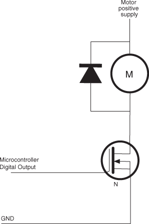
Figure 15-20 IR distance sensor
The diode is there to protect the MOSFET against the large back emf currents that can flow when driving inductive loads like motors.
Life gets more complicated when we want to be able to drive the motor in both directions. To reverse the direction of a DC motor, just send the current through it in the opposite direction. That is, you reverse the polarity of the voltage across its terminals, so the side that was connected to ground becomes connected to the positive supply, and vice versa.
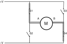
The normal approach to switching the current direction like this is to use something called an H-bridge. Figure 15-21 shows the operation of an H-bridge using four switches. In reality, you would either use four MOSFETs or an IC H-bridge.
In Figure 15-21, S1 and S4 are closed, and S2 and S3 are open. This allows current to flow through the motor, with terminal A positive and terminal B negative. If we were to reverse the switches so that S2 and S3 are closed and S1 and S4 are open, then B will be positive and A negative and the motor will turn in the opposite direction.
You may, however, have spotted a danger with this circuit. That is, if by some chance S1 and S2 are both closed, then the positive supply will be directly connected to the negative supply and a short circuit will result. The same is true if S3 and S4 are both closed at the same time.
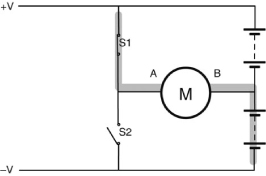
In this project, we sort of use half an H-bridge, because we have a split power supply, so one side of the motor is always connected to the middle voltage from the battery, and to get it to move in either direction, all we have to do is make the other connection connect to either the positive supply or ground. This is shown in Figure 15-22 in a simplified form using switches.
As with a full H-bridge, you can see that if both S1 and S2 are closed at the same time, there will be a short circuit across the battery. If S1 and S2 are transistors, then the resulting high current has nothing much to limit it and the transistors will probably be fried.
Some H-bridge implementations, especially those that use an IC, will include built-in protection so a software error cannot result in a short circuit.
Summary
Arduino boards make great controllers for a robot. They are relatively easy to program and have a good selection of input/output pins. This is a very flexible design, which could lend itself to many possibilities.
Some things you could do with your robot base are:
![]() Attach a WiFi webcam to it
Attach a WiFi webcam to it
![]() Remote control it using Bluetooth
Remote control it using Bluetooth
![]() Attach a mini vacuum cleaner to it and make your own autonomous hovering robot
Attach a mini vacuum cleaner to it and make your own autonomous hovering robot
![]() Arm it with the coil gun from Chapter 2
Arm it with the coil gun from Chapter 2
This book should provide the Evil Genius with all the necessary technology to achieve world domination. Having imparted his knowledge to fledgling Evil Geniuses all over the world, it just remains for the Evil Genius to insist that his followers direct themselves to the website www.dangerouslymad.com. Here, you will find further information about the book, and useful resources such as the message designer for the persistence-of-vision display.