
CHAPTER 13
Levitation Machine

WHEN PLANNING CAMPAIGNS for world domination, the Evil Genius likes to have his globe of the Earth float in the air above his desk, suspended by invisible anti-gravity forces (Figure 13-1).
Actually it’s a ping-pong ball painted to look like a globe, and it’s suspended using something called electromagnetic levitation. Keeping the globe in place requires careful control of the current to the electromagnet, so this project uses an Arduino interface board that is programmed from your Mac, PC, or Linux computer.
The Arduino is a great platform for this kind of situation, and the Evil Genius has used this as the basis for many projects, including that in Chapter 8 and one later in Chapter 15. Any interested Evil Geniuses may wish to check out the book 30 Arduino Projects for the Evil Genius by the same author and publisher as this book.
What You Will Need
You will need the following components to build this project. They are listed in the Parts Bin on the next page.
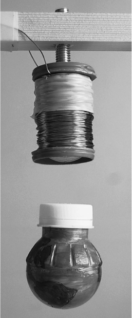
Figure 13-1 The anti-gravity machine in action

The dimensions of the wood are not critical, as long as the upright sides of the frame are about 3½ inches (90mm) apart, so use whatever lumber you have on hand.
You will also need the following tools shown in the Toolbox.
Figure 13-2 shows the complete project.
![]() An electric drill and assorted drill bits
An electric drill and assorted drill bits
![]() Soldering equipment
Soldering equipment
![]() A hot glue gun or epoxy resin glue
A hot glue gun or epoxy resin glue
![]() A wood saw
A wood saw
![]() PVC insulating tape
PVC insulating tape
![]() A computer to program the Arduino
A computer to program the Arduino
![]() A USB-type A-to-B lead (as used for printers)
A USB-type A-to-B lead (as used for printers)
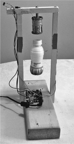
Figure 13-2 The anti-gravity machine
Assembly
The following step-by-step instructions lead you through making the anti-gravity machine. Most of the components are either soldered directly to one another or plugged into the Arduino board, so there is no need for a circuit board.
Step 1. Create the Coil Former
It’s difficult to get hold of suitable coils for this kind of thing, so we are going to wind our own. This sounds difficult, but actually it’s not at all. The wire will be wrapped around a large bolt and we will use two bottle caps as the end points to contain the wire.
The first step in this is to cut the rims off the bottle caps so they are just plastic discs about 1½ inches (35mm) in diameter. We then need to drill holes in the center of each disc, the same diameter as the bolt shaft.
Fit one of the washers up against the head of the bolt and position the other washer to rest against the nut, so that the gap the coil will be wound about is 1¼ inches (30mm).
Next, wrap a single layer of tape around the bolt (Figure 13-3) to protect the enameled wire from the rough edges of the bolt’s thread.
Step 2. Wind the Coil
About 700 turns of wire will be wound onto the bolt. Fortunately, we do not need to count the turns as we add them. If we fill up the space to the right depth, we should be close enough. We can also verify this by measuring the resistance of our coil, which should be between 3Ω and 5Ω.
Even better, we do not need to roll each of these turns by hand. Instead, we can use an electric drill set at its slowest speed to do it for us. Figure 13-4 shows the arrangement.
The spindle of wire is sitting on a screwdriver fixed into a vice, but it is equally practical to make a minion hold onto it. One end of the bolt is then secured in the drill chuck.
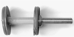
Figure 13-3 The bolt and homemade washers

Figure 13-4 Winding using an electric drill
Before we start using the drill, we need to get the coil started.
Leave about 4 inches (100mm) of wire sticking out from the bolt at the end furthest from the head of the bolt. This will be one of our connections to the coil. Then, wind a few turns by hand to keep this loose end in place. Afterward, attach the bolt to the drill and very slowly (at first) let the wire be wrapped around the bolt. It does not matter if the coils are not laid down exactly next to each other. It is very hard to do this and it is not essential. But do try to direct the wire back and forth across the bolt in as even a manner as possible.
When the windings are about up to the top of the bottle caps, stop winding. Before cutting the wire, we should carry out a quick resistance test to make sure we have approximately the right number of turns.
Carefully scrape away a small section of the enamel from both the lead that we started with and the wire that we were feeding onto the coil. Measure the resistance using a multimeter. It should be somewhere between 3Ω and 5Ω—ideally, 4Ω.
If the resistance is less than 3Ω, we need to add some more turns of wire to the coil. Do not worry about insulating the wire where you scraped away the enamel; the rest of the wire is insulated, so you will not cause a short circuit.
If, on the other hand, the resistance is greater than 5Ω, we need to take some turns off the coil until we bring it under 5Ω.
When you are happy with the coil, cut the wire, leaving four inches (100mm) free, and use some insulating tape to fix the wire in place (Figure 13-5).
Step 3. Build the Frame
We need a frame from which to mount the coil, Arduino board, and other components. This is easily made from four pieces of wood (Figure 13-6).
The base is made from a length of wood 1½″
(90mm) × 3½” (40mm). This is really overkill, but happens to be what the author had lying around and does have the benefit of providing a really solid base. A smaller piece of wood is fine as long as the gap between the two uprights is about 3½″ (90mm). The uprights and top piece are all secured in place with wood screws. Drill holes first with a drill bit slightly smaller than the screws to prevent splitting of the wood.


Figure 13-6 Design of the wooden frame
The holes in the uprights (Figure 13-7) are 5mm in diameter so that the LEDs and phototransistor fit snugly into the holes. They should be drilled out a little with a wider bit on the inside of the uprights to remove any flakes of wood that may obscure the beam of light and to also give a slightly wider angle of view should the LED and phototransistor be misaligned.
Four holes allow for fitting the phototransistor and IR LED at different positions. The LED and phototransistor will initially be in the second hole from the top, but you may find that you need to move them up or down depending on the strength of your permanent magnet (the one in the object to be levitated) and the weight of the object.
Drill a hole that’s the same diameter as the bolt. Ideally, the bolt will self-tap into the wooden top-piece so that its height can be fine-tuned by turning it. You can alternatively use a second nut on top of the cross-piece for this purpose.
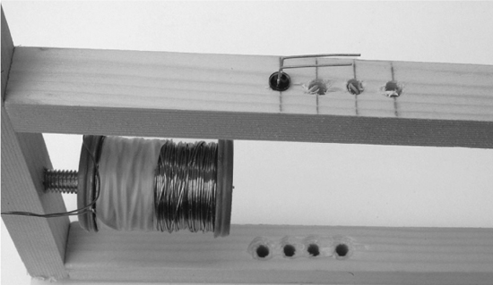
Figure 13-7 5mm holes in the uprights
Figure 13-8 The completed frame with the coil attached
The completed frame should look something like Figure 13-8. Note that the author is no kind of carpenter!
Step 4. Mount the Transistor and Diode
We can now mount some of the electronics onto the frame. The transistor is fixed in place using one of the screws that hold the top piece of the frame in place (Figure 13-9).
Using Figures 13-9 and 13-10 as a guide, solder the negative lead of D2 (no line) to the center lead of the transistor T2. Attach the two leads from the coil to either side of the diode D2. It does not matter which lead from the coil goes to which side of the diode.
For reference, the schematic diagram is also shown in Figure 13-11.
Cut two lengths of reasonably thick wire about 12 inches (300mm) long and attach one to the positive side of D2 (bar) and one to the rightmost pin of the transistor (the source). Ideally, the first should be red and the other black. Eventually, these will be soldered to the power connector of the Arduino board.
Figure 13-9 The components on the top of the frame
Figure 13-10 The wiring diagram for the project
Step 5. LED and Phototransistor
We will fit the LED and phototransistor into the second hole down from the top of the frame opposite each other, with the transistor on the left hand side as the frame faces us.
Cut off the third “base” lead of the phototransistor since no connection is going to be made to this. Then, bend the two remaining leads and the leads of the LED (D1) so they are at right angles to the facing direction of the LED. This way, when they are inserted into the holes, they will lie flush with the frame.
Shorten the leads of R1 (100Ω) and solder one end to the longer positive lead of the LED. Next, attach wires of about 10 inches (250mm) in length to the other end of the resistor (R1) and the unused lead of the LED. The ends of these wires will be attached to the Arduino board.
Similarly, attach wires of the same length to the two remaining leads of the phototransistor.
Step 6. Attach the Arduino Board
We have now almost completed the electronics. All we need to do is attach all these wires to the Arduino board.
Start by soldering the power leads to the outside connections of the power socket. This is so the coil can draw current directly from the power supply without it having to go through the board. A close-up of the connections is shown in Figure 13-12.

Figure 13-11 The schematic diagram for the project
Figure 13-12 Close-up of the power connections
The other wires will all be just poked into the sockets that line the edge of the board. If you used multi-core wire, this will be easier if you tin the wires with solder first.
Starting with the leads from the LED, attach them as shown in Figure 13-10. That is, one lead to the GND socket and the other to the Digital 13 socket.
Wiring the phototransistor is a little more difficult because we are going to attach R2 at the same time. Put one end of R2 into the 5V socket and fit both the other end of R2 and the lead going to the collector of the phototransistor into the Analog In 0 socket.
Step 7. Set Up Your Computer with Arduino
To be able to program your Arduino board with the control software for the levitator, you first need to install the Arduino development environment on our computer. If you completed the persistence-of-vision project of Chapter 8, you will already have the Arduino software setup.
For installation and setup instructions, please refer back to Chapter 8 and the Arduino web site (www.arduino.cc).
Step 8. Program the Arduino Board
Without connecting the power supply to the board, connect a USB cable between your computer and the Arduino board. You should see the red power LED come on, and if it is a new board, a small LED in the middle of the board will be flashing slowly.
Launch the Arduino software. Copy and paste the code for the application, which can be viewed at www.dangerouslymad.com, into a new project (see Figure 13-13), and then save the sketch as antigravity. The word “sketch” denotes a program in Arduino parlance.
To actually upload the software onto the Arduino board so it can function without the computer, click the Upload button on the toolbar. There will now be a furious flashing of little lights on the board as the program is installed on the Arduino board.
Before we make something to levitate and try the project out for real, we can carry out a few tests to make sure the sensor and LED are working okay. To do this, we will use the Arduino software’s Serial Monitor. This allows your computer and the Arduino board to communicate. So you can issue commands to the Arduino, and the Arduino can also send back data.
Click the Serial Monitor (the rightmost icon on the toolbar) and after the prompt appears, type m into the text entry box at the top of the monitor (Figure 13-14).

Figure 13-13 Loading the antigravity sketch

Figure 13-14 Testing with the Serial Monitor
You will then see a stream of numbers. The first number of each row is the position of the object (if any) that is being levitated, while the second number is the velocity—a positive number if the object is moving down and a negative number if it is moving up.
We do not have any object being levitated, so the position should read a high value, probably around 600. The velocity should be around 0, but may jitter up and down a bit. We can test that the transistor and LED are working okay by putting an object (say a pencil or your hand) in between them. This should decrease the “position” down to 0. You can also try moving the object up and down past the sensor and see the velocity go positive and negative as you move in different directions.
Step 9. Make Something to Levitate
The key to making an impressive distance between the electromagnet and the object being levitated is to put a strong permanent magnet at the top of the object being levitated. We use a neodymium, a rare-earth magnet. Despite their exotic-sounding name, these are easily obtainable from eBay or a hobby shop.
We could just levitate a metallic object such as a nut or bolt, but a magnet will produce much better results.
Once you have the hang of it, you can try levitating various kinds of object. For now, we will start with an easy-to-make and inherently stable object based on a very small plastic bottle that used to contain a health drink. The magnet is glued to the inside of the bottle lid, which is then screwed back onto the bottle (Figure 13-15).
Before gluing the magnet onto the lid, we need to find the right orientation for it. The best way to do this is to attach the power supply and wave a hand in front of the beam to activate the coil. Afterward, hold the magnet first one way and then the other to find the orientation that attracts the electromagnet.
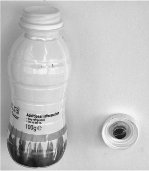
Figure 13-15 Bottle for levitation
A variant on the bottle theme is to take the bottle and cut away just the top section, leaving enough to attach a ping-pong ball to it. This can then be painted to look like a globe. The end result may look something like Figure 13-16.
Step 10. Try It Out
We are now ready to try out the levitation device.
All we need to do is attach the power connector and turn it on. The program that controls the levitation device has a safety feature that turns the coil off if there is nothing being levitated. So, to activate it, we need to move the bottle up and down a bit near the phototransistor.
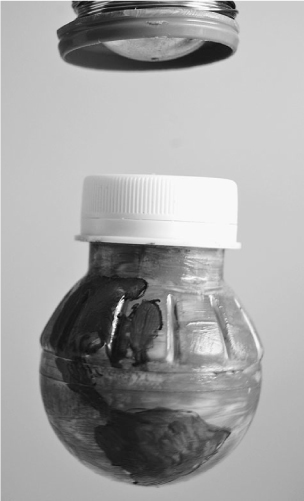
Figure 13-16 A globe for levitation
If all is well, you should feel the electromagnet pull at the bottle as the bottle moves down, and relax as you move the bottle up. If you get too close to the electromagnet, you will start to feel the permanent magnet attracted to the steel bolt in the electromagnet. Therefore, you should keep the bottle out of this area.
Try to feel the forces acting on the bottle by lightly holding it from the bottom. Gradually let the bottle go and you should feel it being held by the electromagnetic force (Figure 13-17).
If there is nowhere near enough force to support the object, you may need to move the phototransistor and LED to the top hole, or move the electromagnet downward by screwing it further out of the wood.
Figure 13-17 Levitation in action
If on the other hand the object always just flies straight up to the magnet and attaches itself to the metal bolt, you need to move the electromagnet and permanent magnet further apart.
Once you have the basic spacing about right, you may find that the bottle jumps about, rather than remaining in a stable position. If this is the case, you need to adjust parameters A, B, C, and D in the program. It is most likely to be B that needs adjusting, and fortunately you can alter this without having to change the program. Open the Serial Monitor again as if you were monitoring the position and velocity readings, but instead of entering the m command, you have two other commands. Entering a B and pressing ENTER will increase the value of B, and entering a lowercase b will decrease it. While holding onto the bottle, change the value of B until maximum stability is achieved.
Note that if you use the m option to turn on monitoring, this slows everything down, and the levitation will not work. So you cannot use the monitoring feature while simultaneously adjusting the value of B.
The Arduino board will not remember the new value of B after the power has been off, so once you have determined the best value, modify the sketch and upload it to the Arduino board again.
Theory
This project contains loads of science, from electromagnetism to Newtonian mechanics.
Basic Principles
As you will have gathered by now, the basic idea behind levitation is that as the object being levitated moves below the desired point, the power to the electromagnet is increased, and as it rises above that point, the power is decreased.
However, using only this approach, the object will just bounce up and down, becoming more and more unstable. You can try this by changing the value of B to 0 using the Serial Monitor in the way we described earlier. To achieve any kind of stability, we must take the velocity of the object into account. If the velocity indicates that the object is above the desired position but is traveling downwards quickly, we need to ease off the power early, or the object will overshoot the target.
The formula for calculating the power is:
Power = Position / A + B × Velocity + C
The purpose of A is to scale down the value of the position from its maximum value of about 600 to the maximum value of around 255 needed to output to the coil. So in this case, halving it is about right. If the value for the position in your arrangement is say 900 rather than 600, you should increase A to 3. Note that A is an integer value, so you cannot change it to 1.5.
Position Sensing
Figure 13-18 illustrates the way we sense the position of the item being levitated. The position is sensed by measuring the amount of IR light being obscured by the object.
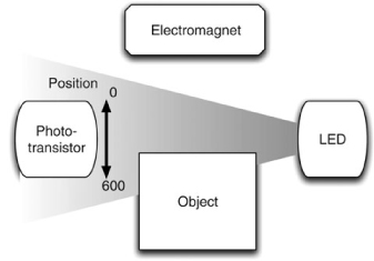
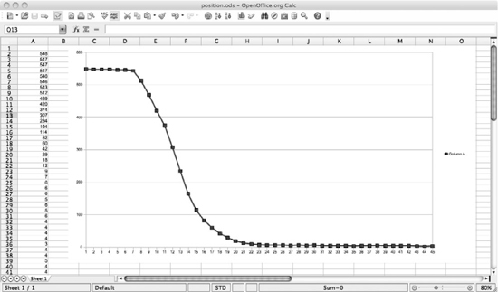
Figure 13-19 A plot of position
Figure 13-19 shows a plot of the value of the “position” variable as an obstruction (a piece of card) is gradually moved across the sensor area from bottom to top. Each step on the X axis represents one reading, while the Y axis shows the value of the “position” variable.
You can easily make your own plot like this using the Serial Monitor to capture some position and velocity readings and then paste them into a spreadsheet.
The plot clearly shows that the phototransistor starts being obscured at around sample 7 and is fully obscured by about sample 23. This means that over the 5mm distance range that the sensor covers, we can resolve about 550 different values, which is pretty accurate.
Ambient Light Compensation
A light sensor for determining the position of the item being levitated can suffer from problems with changes in ambient light. That is, if someone turns the lights on or the sun comes out, more light would enter the phototransistor, giving a false reading for the position.
This anti-gravity machine uses a cunning technique to compensate for such changes. It momentarily turns off the LED, takes a measurement of the ambient light, and then turns the LED back on again. All of this within a few thousandths of a second. The software for doing this is described in the next section.
Figure 13-20 shows a plot of the variables in the program for “raw” light intensity, ambient light intensity. and the difference between the two. The first two of these are captured using the Serial Monitor with a modification to the software to write out the values of the “raw” and “ambient” variables.
The first thing to notice is that the raw value is considerably higher than the ambient value. This means that the IR LED is doing its work and shining a bright beam into the phototransistor, so we are naturally keeping the influence of external light fairly low.

Figure 13-20 A chart showing ambient light compensation
The difference line remains fairly flat, which is what we want, and means that external influences such as turning on a bright light near the levitator (between samples 43 and 90) and shading it with a large box (between samples 118 and 180) were both compensated for.
Interestingly, you can see the mains frequency flicker from that first event, where the brightness of the lamp fluctuated with the mains frequency. This leaves a small trace on the compensated signal, but not enough to worry about.
Control Software
If you have not used Arduino before, then hopefully you will be impressed by the simplicity and power of this little microcontroller board. Let’s have a look at the program that controls the levitation machine. (See Listing 13-1.)
The Arduino boards use the C programming language. It is beyond the scope of this book to explain the whole C language, but if you have a basic familiarity with programming, you should be able to understand the following explanation.
The program starts with some variable declarations. The lines that start with a // denote comment lines that explain what is happening.
We then have a “setup” function that says how the various connections on the board are to be used, and sets the baud rate for communication with the Serial Monitor. A message saying what commands can be issued is then echoed to the Serial Monitor.
// Project 13 - Anti-gravity
// 15 Dangerous Projects for the Evil Genius


#define coilPin 11
#define irPin 13
#define sensorPin 0


int A = 2;
// Adjust B to improve stability
int B = 60;
int C = 20;
int D = 1000;


int maxPower = 255;
long powerCountThreshold = 300000;
int objectPresent = 0;
int monitoring = false;


void setup()
{
  pinMode(coilPin, OUTPUT);
  pinMode(irPin, OUTPUT);
  pinMode(sensorPin, INPUT);
  Serial.begin(9600);
  Serial.println("Ready");
  Serial.println("m - toggle monitoring");
  Serial.println("B - increase B");
  Serial.println("b - decrease B");
}


void loop()
{
  static int count = 0;
  static int oldPosition = 0;
  static int ambient = 0;
  static long powerCount = 0;
  count ++;


  if (count == 1000)
  {
     ambient = readAmbient();
     count = 0;
     objectPresent = (powerCount > powerCountThreshold);
     powerCount = 0;
  }
  int raw = 1024 - analogRead(sensorPin);
  // position from top (0) of sensor region to the bottom (650)
  int position = raw - ambient;
  // positive value means going downwards, negative going upwards
  int velocity = position - oldPosition;
  int power = position / A + velocity * B + C;
  powerCount += power;
  oldPosition = position;


  // clip
  if (power > maxPower) power = maxPower;
  if (power < 0) power = 0;


  checkSerial();


  if (monitoring)
  {
     Serial.print(position);  Serial.print(",");
     Serial.println(velocity);
  }


  analogWrite(coilPin, power * objectPresent);
  delayMicroseconds(D);
}


int readAmbient()
{
  digitalWrite(irPin, LOW);
   // allow time for LED and phototransistor to settle
  delayMicroseconds(100);
  int ambient = 1024 - analogRead(sensorPin);
  digitalWrite(irPin, HIGH);
  return ambient;
}


void checkSerial()
{
  if (Serial.available())
  {
     char ch = Serial.read();
     if (ch == 'm')
     {
       monitoring = ! monitoring;
     }
     if (ch == 'B')
     {
       B += 5;
       Serial.println(B);
     }
     if (ch == 'b')
     {
       B -= 5;
       Serial.println(B);
     }
  }
}
The “loop” function is automatically run repeatedly. It is this loop that controls the coil.
First, we define some static variables that will retain their value between calls of the function. The variable “count” is incremented each time “loop” is run; “oldPosition” is used to find the change in position between samples, and hence the velocity; “ambient” is used to contain the ambient light intensity when the LED is off; and, finally, “powerCount” is used to keep track of how long the coil has been on and whether anything is being levitated or not.
The “if” statement allows the code inside it to be run just one time in every thousand. The first thing it does is measure the ambient light—that is, the light reading you get when the LED is off. This is then used to adjust the light reading so the levitation device is not affected by changes to the lighting when a light is turned on. This happens because the “readAmbient” function momentarily turns off the LED and takes a reading of the light before turning the LED back on again.
The next part of the one-in-a-thousand block sets the “objectPresent” variable depending on the accumulated “powerCount.” This is important because it allows the coil to be turned off when there is no object being levitated. If we did not do this, then maximum power would be flowing through the coil whenever there was nothing being levitated. This would make the coil dangerously hot after a while.
After the “if” statement, we do the calculations to find the position and velocity, and then calculate the power we should apply to the coil. If the power is outside the range for the analog output, then the next few lines “clip it.”
The “checkSerial” function checks for any incoming commands from the Serial Monitor and processes them. If the m command is issued, then the “monitoring” variable is set. Back in the “loop” function, if “monitoring” is true, then the position and speed will be written to the Serial Monitor. While this is happening, it will slow everything down, likely causing levitation to fail.
Finally, we write the power level to the analog output controlling the power, and then delay for a period of time determined by parameter D before beginning the whole process again.
Summary
This is one of the easier projects in the book to build, but one of the most difficult to get right. It will probably take some experimentation on your part to make it all work. But the first time you get something to levitate, it all becomes more than worthwhile.
Feel free to experiment with levitating other items—even items without a magnet in them. To do this, however, you will need to move the sensor closer to the electromagnet.
In the remaining two chapters of this book, we switch our attention to two very different kinds of robots. Next stop: a tiny light-seeking robot that uses toothbrush motors.