
CHAPTER 7
Laser-Grid Intruder Alarm

LASER BEAMS LINE THE ENTRYWAY to the Evil Genius’ Lair (Figure 7-1), forcing the secret agent to bend and arch through the beams in a series of agile moves. With skills honed by years of Twister and limbo dancing, the agent navigates his way through the beams. Suddenly an alarm sounds and vertical doors slam to the ground, trapping the agent. The Evil Genius triumphs again.
This is a working alarm. It uses a laser beam that bounces between mirrors attached to two walls that face each other. For instance, the entrance to the Evil Genius’ Lair. When the beam is broken, a buzzer sounds.
Note that the more ingenious agent will work out that they can defeat the alarm by attaching a flashlight to the sensor, or indeed just turning it off. Figure 7-1 has also been Photoshopped to show the path of the beam.
The Evil Genius also likes to amuse himself by holding “Laser Limbo” competitions at his sadly under-attended parties. To shouts of “How low can you go?” the Evil Genius limbos under the beam. The wise minion will hide when the buzzer sounds.

You should always take certain precautions when using lasers:
![]() Never shine a laser into your eyes or anyone else’s.
Never shine a laser into your eyes or anyone else’s.
![]() Resist the temptation to check if a laser is on by peering into it. Always shine it onto a sheet of paper or some other light surface.
Resist the temptation to check if a laser is on by peering into it. Always shine it onto a sheet of paper or some other light surface.
What You Will Need
You will need the following components to build this project.
You can buy laser modules from standard component suppliers like Farnell and RS, but they tend to be very expensive. So look online, where they should cost no more than two or three dollars.
The mirrors were bought in a pack of six from a hobby and craft retailer.
The plastic packing material should allow light to pass through it, but it will diffuse the light like frosted glass.
In addition, you will also need the following tools, shown in the Toolbox.
Figure 7-2 shows the schematic diagram for this project.

![]() An electric drill and assorted drill bits
An electric drill and assorted drill bits
![]() Soldering equipment
Soldering equipment
![]() Glue
Glue
The circuit is very similar to the balloon popper part of Chapter 5. However, in this case we want to know when the beam is interrupted. For this reason, the phototransistor is connected as a “common emitter”—that is, the emitter of the transistor is connected to ground rather than the collector being connected to the positive supply as in the balloon popper.
Assembly
The following step-by-step instructions lead you through making the laser alarm. It is quite a simple design, so we can actually build it without a circuit board.
Step 1. Drill the Control Box Lid
Most of the holes for this project are going to be made in the lid of the project box. For the sake of neatness, it’s a good idea to line them all up along the center of the box. So start using a ruler and pencil to draw a line on the inside of the lid from one side to the other across its long side.
Next, lay out the LED, switch, variable resistor, and the expanded plastic packing material that you are going to use as a diffuser. Make sure there is enough room around each of these components and mark the point on the line where you need to drill. Drill holes for all the components. Drill a relatively large hole that is slightly smaller than the diffuser. The author also enlarged and squared off this hole with a file. However, this is not essential.

Figure 7-2 The schematic diagram for the laser alarm
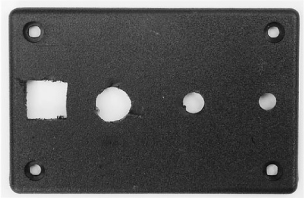
Figure 7-3 The box lid, drilled
Figure 7-3 shows the lid drilled and ready to accept the components.
You can now attach the LED, switch, and variable resistor. If you drill the hole for the LED with a 5mm drill bit, the 5mm LED will fit tightly and stay in place without the need for a holder.
Step 2. Drill the Control Box
We must now drill in the control box itself. We need a hole to accept the 2.1mm power socket, two holes for the connections to the buzzer, and a hole for the lead to the laser.
Plan out the placement of the holes so they are well away from the other components on the lid. Before drilling the holes, put the lid on to make sure everything fits in the box.
Figure 7-4 shows the box itself drilled.
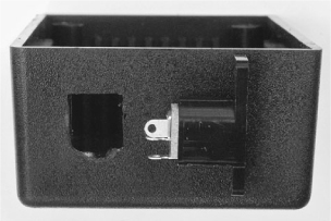
Figure 7-4 The project box, drilled
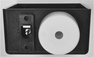
Figure 7-5 The project box with buzzer and socket fitted
Push the leads of the buzzer through the two holes and glue the buzzer into place on the side of the box (Figure 7-5).
Step 3. Wire Up the Lid
Using Figure 7-6 for guidance, wire up the components on the lid.
Figure 7-7 shows the box lid with the main components attached, while Figure 7-8 shows some of the other components attached.
Bend the wires on the phototransistor so it faces the diffuser. Attach leads that will connect to the power connector and buzzer in the box.
Step 4. Wire Up the Laser Module
Solder the leads from the laser module to one end of the six-foot (1.8m) twin core cable (Figure 7-9). If possible, use cable that has a stripe or some way of indicating which core is to be used as positive. If the cable is unmarked, use a multimeter to ensure that the laser module is wired up with the correct polarity.
Insulate the leads with PVC insulating tape.
To relieve the strain on the cable, we are going to thread the cable through the hole in the project box and then tie a knot in it. We can then strip the ends of the cable and attach the negative lead to the outer connection of the power socket. The positive connection will attach to the 100Ω resistor R4, whose leads should be cut short. Attach a short length of multi-core wire to the other end of the resistor ready to be connected to the switch.
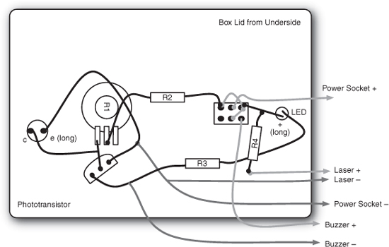
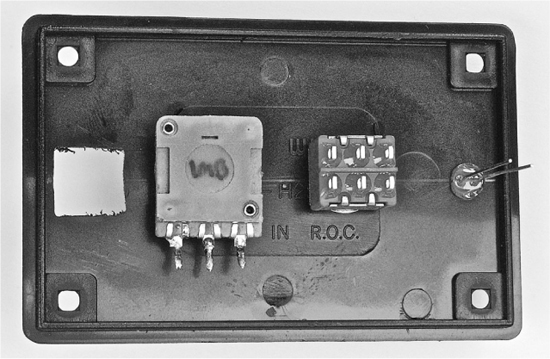
Figure 7-7 The box lid, main components attached
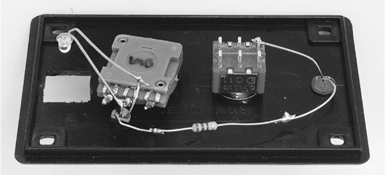
Figure 7-8 The box lid, partially assembled

Figure 7-9 Attaching the laser to the cable
Step 5. Complete the Wiring
We can now wire up the box itself and connect it to the lid.
Start by attaching the positive and negative power leads to the appropriate leads of the power socket. Always solder the lead that is most inaccessible first, because it will only become less easy to reach as other things are soldered into place.
Next, attach the leads to the buzzer and finally the lead from R4 to the switch.
Figure 7-10 shows the completed wiring.

Figure 7-10 The completed wiring
Testing
Before we screw down the box lid, we should try a simple test to make sure that everything is working. You will probably want to do this with the switch in the “mute” position.
Attach the power supply and turn it on. Cover up the diffuser so it is dark. This should cause the LED to light. If the LED was already lit when the power was turned on, try shining the laser module at the diffuser. The LED should go out. If this does not happen, then something is wrong and you need to go back and check your circuit.
You can now fasten the box together and adjust the variable resistor until the LED is just on. Shine the laser onto the diffuser and it should go out. Then, move the beam away from the diffuser and the LED should light as if the beam had been broken.
The completed control box is shown in Figure 7-11.
Installation
We now come to the installation of the alarm. This requires us to fix the laser module to the wall, as well as the three mirrors that are going to direct the path of the laser. Figure 7-1 will remind you of the way the alarm is laid out.
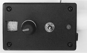
Figure 7-11 The completed control box
To do this, we are going to have the laser turned on and then place the mirrors rather than try to fix the mirrors in place first.
Start by fitting a large lump of the adhesive putty around the laser module and fit it at about head height to the wall, pointing down at an angle of about 30 degrees (Figure 7-12).
Please note that while the Evil Genius is not too concerned about the décor of his lair, you might be, and the use of adhesive putty on painted walls generally causes a mess and the loss of some of the paint when you finally remove the putty.
Using a small bit of the putty, attach one of the mirrors on the wall opposite the laser about one third of the way to the ground. This mirror should be flush to the wall. Adjust the laser, moving it in the putty until it hits as near the center of the mirror as possible.
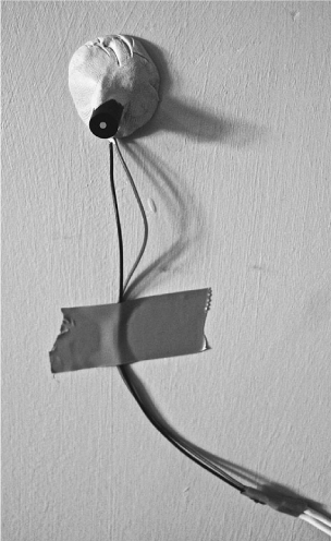
Figure 7-12 Fixing the laser module to the wall
Now fix the next mirror where the dot appears on the wall opposite. Repeat this for the last mirror, which should be attached to the wall with a bigger bit of putty to allow it to be angled slightly back to the control box.
The control box should be fitted so the laser hits the diffuser. At this point, the LED should turn off and the alarm is successfully installed.
This is a project that requires a little trial and error to get right. You may find that your laser is bright enough and your mirrors good enough to achieve more bounces over a greater distance.
You may prefer not to use a mirror at all but instead protect a longer region with a single beam pointing directly into the control box.
Theory
This alarm is interesting in that it shows the difficulty of accurately positioning a laser and mirrors. Walls are never completely flat, nor absolutely vertical. Mirrors are not perfect reflectors and the laser beam itself will not travel in a tight beam forever before it loses much of its brightness.
Although when you shine a laser on a distant wall at night it may seem like lasers travel for a tight beam forever, actually they don’t. The type of coherent light they use is easy to focus, but it must actually be focused and the laser module includes a glass or plastic lens to accomplish this.
Lenses are never perfect and hence the beam, although very narrow, will eventually diverge. The more it diverges, the more spread out the light and therefore the dimmer it is where it hits a small sensor like our phototransistor.
Summary
An improvement on the design would be to use a bistable latch, so that once triggered, the buzzer does not stop sounding until the alarm is reset. If you search the Internet for “bistable latch,” you should find some resources and an explanation for the adventurous reader on how to try this modification.
In the next chapter, we are going to meet an Arduino microcontroller board and use it to create an impressive spinning persistence-of-vision effect.