
CHAPTER 6
Touch-Activated Laser Sight

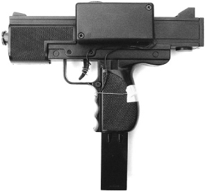
THIS PROJECT ADDS A LASER SIGHT to a BB gun. The laser activates when you touch the trigger prior to firing. This allows the Evil Genius to be far more accurate when carrying out assassinations and other gun-related crimes. Even if it is not connected to the gun, the presence of a bright red dot on the chest of a minion tends to cause an amusing degree of panic.
This project involves a little electronics to make the touch sensor for activating the laser, but this only requires a few components to be connected together. So, if you are looking for a simple project that just requires a bit of soldering to stripboard in order to test your soldering skills, this is an ideal first project for you.
Figure 6-1 shows the completed project attached to a particularly nasty-looking BB gun.
WARNING!
Please take heed of the following safety warning.
![]() BB guns can be dangerous. Fire them at targets, not at people.
BB guns can be dangerous. Fire them at targets, not at people.
![]() Never shine a laser into your eyes or anyone else’s.
Never shine a laser into your eyes or anyone else’s.
![]() Resist the temptation to check if the laser is on by peering into it. Always shine it onto a piece of paper or some other light surface.
Resist the temptation to check if the laser is on by peering into it. Always shine it onto a piece of paper or some other light surface.
What You Will Need
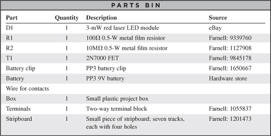
To build this project, you will need the components shown in the Parts Bin on the next page.
You can buy laser modules from standard component suppliers like Farnell and RS, but they tend to be very expensive. So look online, where they should cost no more than two or three dollars.
In addition, you will also need the following tools:
![]() An electric drill and assorted drill bits
An electric drill and assorted drill bits
![]() Soldering equipment
Soldering equipment
![]() Epoxy resin glue or a hot glue gun
Epoxy resin glue or a hot glue gun
Figure 6-2 shows the schematic diagram for this project.
The laser diode module is controlled by a FET. The gate of the FET is pulled to ground by R2. However, when the two contacts are bridged by the resistance of someone’s hand, it increases the voltage at the gate enough to turn on the MOSFET and light the laser.
Assembling the Sight
All the components for this project are built into a small plastic box, with wires that lead to the triggering contacts (Figure 6-3).
Step 1. Drill the Box
Place the battery, terminal block, and laser module into the box in the arrangement shown in Figure 6-4 and mark the outside of the box where you need the light from the laser module to emerge. Drill a ¼-inch (6mm) hole.
We need to make two smaller holes at the other end of the box for the wires of the touch sensor to enter the box and attach to the terminal block. Make the holes just big enough for the two wires. Figures 6-5 and 6-6 show the drilled box.
Step 2. Create the Touch Sensor
The touch sensor uses two contacts, one around the handle of the gun and one on the trigger. The contact on the trigger is made by stripping about an inch and a half of solid core wire and wrapping it around the trigger.
The other contact is wrapped around the handle in a similar way. A bit of tape is used to keep the wire on the handle in place. (See Figure 6-7.)

Figure 6-2 The schematic diagram for the BB-gun gunsight

Figure 6-3 The laser sight ready to be attached to the gun
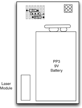
Figure 6-4 The layout of the components in the box
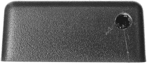
Figure 6-5 The drilled box (front)
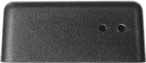
Figure 6-6 The drilled box (rear)
Step 3. Stripboard Assembly
Begin by cutting the stripboard to size. A strong pair of scissors will manage this just fine. Figure 6-8 shows the stripboard layout for the project. It is pretty minimal as there are only three components to put on the board.
First, solder in a short length of solid core wire between tracks 4 and 7.
Solder the two resistors onto the clipboard and then the transistor. Make sure you get the transistor the right way around. The completed board is shown in Figure 6-9.
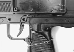

Figure 6-8 The stripboard layout
Step 4. Fit It into the Box
Lay out the components in the box in the arrangement shown in Figure 6-10, and then shorten the leads of the battery clip and the laser module. They should just reach the point where they will be soldered to the stripboard, with a little bit to spare.
Solder the battery and laser module leads to the stripboard as shown in the wiring diagram of Figure 6-10.
We can now test that it works by connecting the battery and temporarily fitting two wires to the points where the sensor will be attached. When you touch both wires, the laser module should illuminate. It is easier to test everything before you put it in the box.
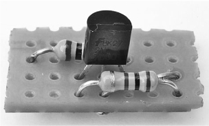
Figure 6-9 The completed stripboard
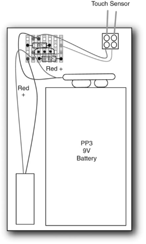
Figure 6-10 The wiring diagram
If everything is all right, we can glue the laser module and terminal strip into place. Use only a small amount of glue so the laser module remains flush with the corner of the box.
Step 5. Finish Up
We can now attach the touch sensor leads to the terminal block and attach the box to the side of the gun. Adhesive putty is a good non-permanent way of attaching the box to the gun. It also allows the angle at which the laser shines to be adjusted a little so it is in line with the gun barrel.
That’s it. A nice simple project.
Testing and Calibration
Trial and error is the best way of calibrating the laser. Fix the laser in one position and then fire the gun, noting the position where you hit the target and tweak the laser toward that point.
The laser will never perfectly light up the place where the pellet will hit for a number of reasons, not the least of which is that BB guns do not shoot very straight. And most especially, if shot over a distance, the trajectory of the pellet will be falling, whereas the light from the laser is immune to the effects of gravity.
Theory
The key components of this project are the laser diode and the FET transistor. We now take a detailed look at these two componets.
Laser Diodes
The word laser was originally written as LASER because it stands for Light Amplification by Stimulated Emission of Radiation, but these days it is just written as “laser.”
Not that long ago, lasers used to be something you only found in laboratories. They create a beam of light at exactly one frequency (color). They also have the property of coherence, which means that all the waves of the light are in step and don’t overlap each other. This makes it possible to use a lens to focus them into a very narrow beam that remains a small dot even when aimed at something quite distant.
Lasers have become cheap and easy to obtain because of the laser diode, which is a similar technology to regular LEDs but generates laser light rather than ordinary incoherent light. These are used in CD and DVD players.
A laser diode on its own is not enough to produce the narrow beam of light we want. We need a lens to do that. Since it is quite difficult to get the lens lined up in exactly the right place, the solution is to buy a laser module. A laser module consists of both a laser diode and lens in one sealed unit with two leads coming out the back to supply it with power. Like laser modules that shine a dot, certain varieties shine a cross or a line. You can also now buy green laser modules. Blue laser modules are also becoming available as a result of Blu-ray disk players, which use high-powered blue lasers.
The laser module we are using is very low power—only 3 mW. However, it is possible to buy laser diodes of 300 mW or more, which when focused are capable of popping a balloon and even burning and cutting. Clearly, such devices must be handled with care and respect.
FETs
You may have noticed that our design does not have an on/off switch. This is unnecessary because the transistor we use is a type called a FET (field effect transistor). These transistors differ from the more common bipolar transistors because, rather than having a “base” connection, they have a so-called “gate.” The gate is insulated from the rest of the transistor through which the main current flows. It exerts its influence over the current through the transistor by way of the charge on it. In other words, unlike an ordinary bipolar transistor, which relies on a current to switch the transistor, the FET can be switched just by the presence of potential at the gate. To turn on the current and have the laser light up, simply increase the voltage at the gate to an amount above its threshold voltage.
For the 2N7000, this threshold voltage is around 2V. When the transistor is turned on, it has a very low resistance (typically 1.2Ω). On the other hand, when it is switched off there is a tiny “leakage” current of around 1μA, or a millionth of an amp, which is the reason we don’t need an on/off switch.
In Chapter 5, we encountered a type of FET called the MOSFET, which was employed to control the much higher power of a motor and resistor used as a heating element in the balloon popper.
Summary
In this simple project, we explored how to use a laser diode and FET. You can adapt the basic circuit to make other things “touch-controlled” as well. The FET can control a current of up to 400mA. This is more than enough to power a high-brightness LED (HB LED). So you may feel the urge to experiment and see what else you can do with this circuit.
In the next chapter, we will move away from weapons, toward security, starting with another laser project. The laser beam alarm will use mirrors and another laser module to protect the Evil Genius’ Lair.