|
|
|
|
Manipulating Channels and Matching Artifacts |
|
Any given node within Nuke affects specific channels. You do not have to limit yourself to the channels carried by an imported bitmap or image sequence. You can add, delete, copy, merge, and shuffle channels. You can work with common channels, such as RGB and alpha, or work with more esoteric ones like Depth and Motion. When manipulating specific channels, you can apply various Nuke filter nodes. While filter nodes designed for color manipulation are discussed in Chapter 3, ones specific to artifact matching or artifact removal are discussed in this chapter. (Various artifacts, such as blur and grain, are naturally produced by motion picture and video cameras.) In addition, Nuke offers various nodes that create stylistic results, apply custom filter effects through convolution math, and affect the quality to alpha matte edges.
This chapter includes the following critical information:
• Adding, shuffling, merging, deleting, and copying channels
• Applying convolution filters, including blurs, sharpens, and light effects
• Adding and removing noise and grain
Adding, Shuffling, and Combining Channels
As discussed in previous chapters, you can determine what channels a node affects by setting the node’s Channels menu (Figure 6.1). The node indicates the affected channels by drawing long channel lines along the bottom left of the node icon in the Node Graph. If a channel is unaffected by the node (whereby the channel values remain unchanged), a short channel line is drawn.
FIGURE 6.1 The Channels menu set to the Rgba channel set.
Note that the Channels menu actually determines which channel set is used. A channel set, also referred to as a layer, is simply a group of channels. For example, if the Channels menu is changed to Rgba, the channel set includes red, green, blue, and alpha channels.
You can add one or more new channels to a node by utilizing one of Nuke’s channel manipulation nodes. Additionally, you can delete, copy, merge, and shift channels. The channels may be RGB color channels, alpha channels, or specialty channels, which are described in this section.
Depth. The Depth channel, often called a Z-buffer or Z-depth channel, encodes the distance that objects are from the camera through grayscale values. (Technically, the values are scalar, in that any given pixel holds a single intensity value.) Objects close to the camera receive higher values. Objects far from the camera receive lower values (see Figure 6.11 later in this chapter). Depth channels allow the compositing program to place effects in virtual depth. For example, a blur may be placed in the background but not the foreground. Depth channels are demonstrated in the section “Working with Depth Channels” later in this chapter. A limited number of image formats, such as OpenEXR, can carry a depth channel in addition to RGB and alpha channels.
Motion. When a Channels menu is set to the Motion channel set, four separate motion vector channels are included: forward.u, forward.v, backward.u, and backward.v. In general, motion vectors encode the movement of every pixel within a frame from the current frame to the next frame or from the prior frame to the current frame. The movement is stored as color values, whereby any left/right X axis movement is stored in the u channel and any down/up Y axis movement is stored in the v channel. Forward channels encode movement from the current frame to the next frame, while backward channels encode movement from the prior frame to the current frame. You may find it necessary to add Motion channels when importing motion vector renders generated by an external 3D program. Additionally, Nuke provides several nodes that can generate motion vectors or convert the vectors into motion blur; hence, the presence of Motion channels allows the passing of motion vector information between nodes. Motion channels are demonstrated in the section “Motion Blurring” later in this chapter.
Forward and Backward. When a Channels menu is set to the Forward channel set, the forward.u and forward.v channels are provided. When a Channels menu is set to the Backward channel set, the backward.u and backward.v channels are provided.
Mask. A Mask channel is designed to carry alpha matte information.
RotoPaint_Mask. A RotoPaint_Mask channel is specifically designed for its namesake. You have the option to output the spline shapes or paint strokes generated by a RotoPaint node as an alpha matte by selecting the RotoPaint node’s Output Mask parameter and setting the Output Mask menu to Rotopaint_mask.a. For more information on the RotoPaint node, see Chapter 4.
Adding and Removing Channels
You can add a channel to an output by connecting an AddChannels node (Channel > Add). The channel is set by the AddChannels node’s Channels menu. The value given to the new channel is determined by the Color parameter, as shown in Figure 6.2. For example, the output of a Read node may lack an alpha channel. (If a bitmap or image sequence imported through the Read node lacks alpha, the Read node will not add the alpha information.) Hence, you can connect an AddChannels node to the Read node’s output and change the AddChannels node’s Channels menu to Alpha. If Color is set to 0-black, the alpha channel is 100% transparent. If Color is set to 1-white, the alpha channel is 100% opaque.

FIGURE 6.2 The AddChannels properties panel. The node is set to add an alpha channel to the input. The Color parameter determines the alpha value.
You can add multiple channels with the AddChannels node by setting the Channels2, Channels3, or Channels4 menu to a nonempty value (each menu sits to the right of a word and). However, each new channel receives its value from the Color parameter.
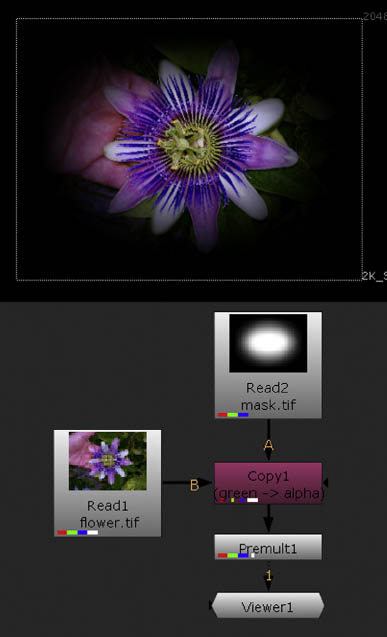
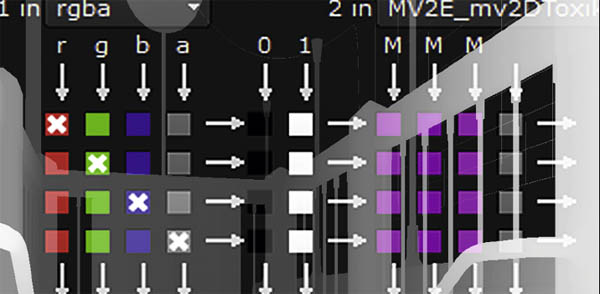
FIGURE 6.3 The alpha channel of a bitmap is replaced by the green channel of a second bitmap through the use of a Copy node. The output is thereby masked. A sample script is included as copychannel.nk in the Chapters/Chapter6/Scripts/ directory on the DVD.
The Remove node (Channel > Remove) lets you delete a channel by selecting the channel name from the Channels menu. You can delete additional channels through the Channels2, Channels3, and Channels4 menus.
Copying Channels
You can copy a channel from one node to another node by using the Copy node. To do so, follow these steps:
1. Choose Channel > Copy. Connect the input A of the new Copy node to the node that will provide the copied channels. Connect the input B of the Copy node to the node that will accept the copied channels.
2. Open the Copy node’s properties panel. Select one or more channels to be copied by setting the Copy Channel From column menus. Select the channels that will be overwritten through the copy by setting the To column menus.
As an example, in Figure 6.3, the opaque alpha channel of a bitmap featuring a flower is overwritten by the green channel of a mask bitmap. The output is therefore masked by an oval shape.
Shuffling Channels
The ShuffleCopy node (Channel > ShuffleCopy) lets you copy the channels of two input nodes to create a synthesized output. The node’s properties panel carries three columns of checkboxes (Figure 6.4). The left column represents the channels brought in by the input 1 pipe. The center column features an optional series of 0 and 1 checkboxes that allow you to set an output channel value to exactly 0 or 1. The right column represents the channels brought in by the input 2 pipe. The output channels are indicated by the left-to-right arrows that run along the rows. By default, only the output 1 pipe is activated, as is indicated by the Rgba setting of the Out1 menu to the far right of the panel. The Out2 menu, below the Out1 menu, is set to None.
You can decide which input channel will become the red, green, blue, and alpha channels for output 1 by selecting the column checkboxes. For example, if you wanted the output alpha to be taken from input 1, select the checkbox that lines up with the input 1 alpha column (labeled a) and select the output alpha row. If you want the output alpha channel to carry a value of 1, select the 1 checkbox that lines up with the central column and the output alpha row. You can mix and match the channel selections. For example, in Figures 6.4 and 6.5, input 1 has its red and blue channels swapped while the green and alpha channels are left intact. In this case, input 2 is ignored (no channels are selected in the input 2 column).

FIGURE 6.4 The red and blue channels of a landscape are swapped with a ShuffleCopy node.
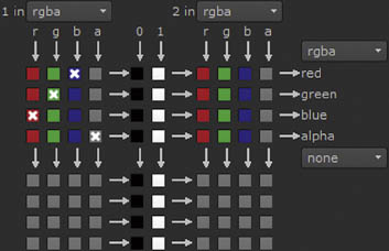
FIGURE 6.5 The ShuffleCopy node’s properties panel, as set up for Figure 6.4. A sample script is included as shufflecopy1.nk in the Chapters/Chapter6/Scripts/ directory on the DVD.

FIGURE 6.6 The blue channel is taken from a Noise node through a ShuffleCopy node. Thus, a blue noisy pattern appears over the landscape.

FIGURE 6.7 The ShuffleCopy node’s properties panel, as set for Figure 6.6. A sample script is included as shufflecopy2.nk in the Chapters/Chapter6/Scripts/ directory on the DVD.
As a second example, in Figures 6.6 and 6.7, the red, green, and alpha channels are taken from input 1 while the blue channel is taken from input 2. Because input 2 is connected to a Noise node, a noisy, grainlike pattern appears over the landscape.
When choosing input channels for inputs 1 and 2, you are not limited to RGBA. You can change the In1 and In2 menus, at the top of the columns, to any standard channel set or channel. The checkbox labels update to reflect the menu changes. You are equally free to change the Out1 and Out2 menus to channel sets or channels of your choice.
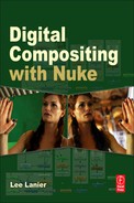
When you change the Out2 menu from None to a channel set or channel, the bottom block of checkboxes becomes unghosted. However, the node retains a single output. The Out2 menu allows you to add four additional channels to the output. For example, Out1 can output the Rgba channel set while Out2 outputs the Motion channel set, which includes forward.u, forward.v, backward.u, and backward.v channels. For example, in Figure 6.8, input 1 provides the Rgba channel set and input 2 provides the Motion channel set. In this case, the In2 menu and the Out2 menu must both be set to Motion to read and output the Motion channels. The column 2 checkboxes automatically change to u, v, u, v.

FIGURE 6.8 The ShuffleCopy node combines the RGBA channels of input 1 and the Motion uvuv channels of input 2 into a single eight-channel output.
In addition, Nuke provides the Shuffle node. The Shuffle node carries the same functionality as the ShuffleCopy node, but only accepts one input. Hence, Shuffle is suitable for shifting channels within a single source.
Merging Channels
You can merge channels from one or two inputs with the ChannelMerge node (Channel > ChannelMerge). The merge is achieved by applying a mathematical merge operation as determined by the Operation menu. The node merges a single channel from input A and input B as defined by the A Channel and B Channel menus. The result is fed to the channel defined by the Output menu. If input A remains unconnected, both input channels are taken from input B. Any channel that is not chosen by the Output menu is taken from input B and is unaltered. As an example, in Figure 6.9, two alpha channels are combined with a ChannelMerge node. The Operation menu is set to Max, which outputs the brightest pixel value when comparing pixels between the two inputs. In this example, the RGB values of the original bitmaps are passed to alpha channels via Shuffle nodes.
Working with Depth Channels
Nuke provides two nodes, through the Filter menu, that are specifically designed for working with Depth channels: ZBlur and ZSlice. ZBlur creates a synthetic depth-of-field effect by reading a Depth channel (Figure 6.10). The strength of the resulting blur is set by the Size parameter, while the maximum amount of blur carried by distant objects is set by the Maximum parameter. The value within the Depth channel that is considered the center of the depth of field (the area in focus) is determined by the Focus Plane (C) parameter. To read the Depth channel appropriately, you must set the Math menu to a specific interpolation. For example, if the Depth channel was generated by Maya, set Math to Far=–0. Maya encodes Z values as –1 / distance from camera (Figure 6.11). For hints on which Math setting to use, hold your mouse over the Math menu to see the help dialog. The size of the depth of field is set by the Depth-Of-Field parameter; smaller values create a narrower focal range. If adjusting the node’s parameters becomes difficult, temporarily select the Focal-Plane Setup parameter. This displays a false-color map where green represents the area within the focal range, red represents areas past the focal range, and blue represents areas in front of the focal range and areas with no geometry.
The ZSlice node, on the other hand, creates an alpha matte based on values contained within a depth file. A range of depth values are converted to opaque alpha, while depth values outside the range are converted to transparent alpha. The center of the range is established by the Center Of Slice parameter, while the size of the range is controlled by the Field Width parameter.
Note that Nuke automatically detects Depth channels. If a Depth channel exists, it’s represented as a purple line to the right of the alpha line on the node icon. To view the Depth channel in the Viewer, change the Viewer’s center Channels menu from Rgba.alpha to Depth.Z and change the Display Style menu from RGB to A (Figure 6.12). (The center Channels menu allows you to replace the alpha channel with a different channel for viewing.) Despite these settings, the Depth channel may appear pure black. For example, a Depth channel created in Maya produces negative values. You can see the values if you place your mouse over the Depth channel and watch the alpha value readout at the bottom of the Viewer panel. Also note that Nuke can read Maya IFF files, as illustrated by Figures 6.10 and 6.11, but cannot write Maya IFF files back out.

FIGURE 6.9 The alpha channels of two inputs are merged with a ChannelMerge node. A sample script is included as channelmerge.nk in the Chapters/Chapter6/Scripts/ directory on the DVD.
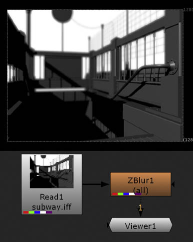
FIGURE 6.10 A synthetic depth-of-field effect added to a 3D render through a Depth channel and a ZBlur node. While the back of the subway entrance is out of focus, the foreground railing remains in focus. A sample script is included as zblur.nk in the Chapters/Chapter6/Scripts/ directory on the DVD.
Alternatively, you can employ a Depth channel as a mask with a Merge node. For example, in Figure 6.13, a Depth channel creates an alpha matte that determines where the output of a Noise node appears over a blue field created by a Constant node. In this case, the Merge node’s Channel Mask menu is set to Depth.Z and the Invert parameter is selected. Because the Depth channel is generated by Maya, it’s necessary to multiply the depth values by a large negative number (which creates positive depth values) through a Multiply node. (For more information on Math nodes, see Chapter 10.)
The ZMerge node (Merge > ZMerge) allows you to combine two depth channels. Depth channel pixels considered “closest” to the camera are output by the node.
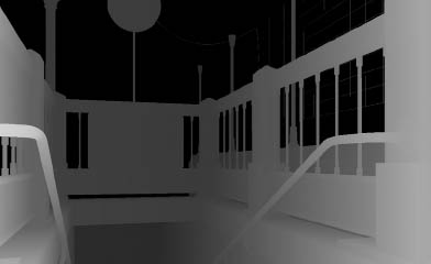
FIGURE 6.11 The Depth channel (as seen in Maya).
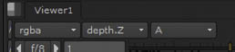
FIGURE 6.12 The two Channels menus (left and center) and Display Style menu (right) set to display a Depth channel.
Adjusting Alpha Mattes
When you generate an alpha matte, either through keying, rotoscoping, or creating a luma matte, it is often necessary to adjust the matte edges. The edges may suffer from stairstepping, where there is harsh transition from 0-alpha to 1-alpha, or the matte may be an incorrect size, causing the matte to fit the foreground element in an ill fashion. Nuke offers the following nodes in the Filter menu that target matte edges.
EdgeBlur softens the matte edge by adding a blurred copy of the edge to the RGB and alpha channels (Figure 6.14). The strength of the blur is set by the Size parameter, while the Edge Mult parameter erodes or expands the blurred area. For example, if Edge Mult is set to a low value, the blurred area is narrow; if Edge Mult is set to a high value, the blurred area is wide. You can adjust the color and brightness of the blurred area by adjusting the Tint and Brightness parameters.
Dilate, which is listed as Erode (Fast) in the Filter menu, provides a simple means to erode or expand the alpha matte. Negative Size values erode the matte, while positive values expand the matte. To avoid disturbing the
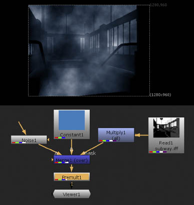
FIGURE 6.13 A Depth channel is used to mask a Noise node output through a Merge node. A sample script is included as zdepthmask.nk in the Chapters/Chapter6/Scripts/ directory on the DVD.
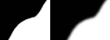
FIGURE 6.14 (Left) Close-up of an alpha matte edge. (Right) The edge after application of an EdgeBlur node with default settings. A sample script is included as edgeblur.nk in the Chapters/Chapter6/Scripts/ directory on the DVD.
RGB channels, set the Channels menu to Alpha. Connect a Premult node to the Dilate node’s output to properly employ the resulting alpha matte.
FilterErode, which is listed as Erode (Filter), works in the same manner as the Dilate node. However the FilterErode node adds a Filter parameter, which allows you to choose the exact style of convolution filter that erodes or expands the matte edge. For example, if Filter is set to the default Box, the node creates a result identical to Dilate, where the expanded matte edge features oversized, square pixels. If Filter is set to Gaussian, the resulting pattern along the edge is much smoother. Note that the FilterErode node’s Channels menu is set to None and the Additional Channels menu is set to Rgba.alpha by default. Much like the Dilate node, you must connect a Premult node to the FilterErode node’s output to properly employ the resulting alpha matte.
Erode, which is listed as Erode (Blur), offers a high-quality means to erode or expand the matte edge. This is achieved by blurring the edge and clamping the resulting values to maintain a relatively quick transition from 0-alpha to 1-alpha. The Size parameter sets the number of pixels by which the matte is shrunk or grown. Blur adds additional softening to the resulting matte edge; higher Blur values create a softer edge. The Quality parameter determines the quality of the initial edge blur: low Quality values create a stairstepped matte edge but will render more quickly; high Quality settings create a smoother matte edge. For a working example of the Erode node, see the Chapter 5 tutorial “Removing an Imperfect Greenscreen.”
Matching Film and Video Artifacts
When motion picture film or digital video is shot, it creates distinct artifacts. The artifacts include depth-of-field blur, motion blur, noise, grain, and patterns created by the lens optics. Compositors are often required to recreate such artifacts so that various elements within the composite match or remain stylistically consistent.
Blurring and Convolution Filters
In the real world, a camera may produce an image that is partially blurred. The blur results from objects falling within an area outside the camera’s depth of field. A depth of field is a range that a camera is able to sharply focus. Areas outside the depth of field are unfocused and thus appear blurry. Real-world camera lenses are able to focus at a specific distance. Depth of fields may be wide or narrow, depending on the lens length, the camera’s aperture setting (f-stop), and the amount of available light (e.g., daytime versus nighttime).
Because depth of fields are an inherent part of photography, cinematography, and videography, the ability to blur elements is an important part of compositing. Aside from recreating depth of field, blurs are stylistically useful for softening elements. Nuke provides several blur filters. The filters are dependent on convolutions. A convolution filter slides a kernel over the image matrix to create averaged pixel color values. A matrix is a rectangular array of numbers arranged into columns and rows. Each pixel of a digital image provides a color value to each image matrix cell. A kernel is also a matrix, but is usually smaller than the image matrix and includes values derived from a specific filter function, such as a blur or sharpen.
The following are descriptions of Nuke’s various blur filters, all of which are available through the Filter menu.
Blur employs a two-pass convolution filter. The size of the filter kernel matrix is set by the Size parameter. The larger the Size value, the more intense the blur. The style of convolution filter is set by the Filter parameter. The Box filter provides a simple and efficient kernel matrix but tends to produce horizontal and vertical edge streaking. The Triangle filter improves the blur by using a matrix that is sensitive to pixel distance. Quadratic and Gaussian filters provide two matrix variations that combine high-quality averaging with a maintenance of object edge detail. Each filter name refers to the shape of the filter function curve that ultimately creates the values used by the corresponding kernel matrix. (Box and Triangle filters use curves in their namesake shapes, while Quadratic and Gaussian filters use bell-shaped curves.) The Blur node’s Quality parameter determines the overall quality of the blur. In effect, low Quality values cause the node to temporarily downscale in input, which causes the output to become blocky and pixelated.
Soften creates a namesake effect by adding a blurred copy of the input to the input (Figure 6.15). This creates a foggy, glowlike look. The blurred copy is created by applying Laplacian and blur convolution filters. Laplacian filters are designed to detect and separate high-contrast edges. The node’s Size and Filter parameters control the blur and function in the same manner as the Blur node. The Minimum and Maximum parameters control the value range targeted by the Laplacian filter. If the value difference between Minimum and Maximum is small, fewer edges are separated. The Amount parameter controls the degree to which the blurred edges are added back to the original input.
Defocus creates a bokeh-based blur. A bokeh is a specific shape created by a lens when a point of light is out of focus. A bokeh corresponds to the shape of the camera aperture opening and generally takes on a circular or polygonal form. The Defocus node creates a circular bokeh (Figure 6.16). The intensity of the blur is set by the Defocus parameter. The height-to-width ratio of the circular bokeh is determined by the Aspect Ratio parameter. Values larger than 1 create an oval-shaped bokeh. The overall scale of the bokeh is set by the Scaling parameter. Large Scaling values create a large kernel matrix, which significantly slows the calculation.

FIGURE 6.15 A Soften node adds a foggy, glowlike blur to an image. A sample script is included as soften.nk in the Chapters/Chapter6/Scripts/ directory on the DVD.

FIGURE 6.16 Close-up of background detail blurred with a Defocus node. Small, bright areas take on a circular shape. A sample script is included as defocus.nk in the Chapters/Chapter6/Scripts/ directory on the DVD.
Convolve allows you to create a custom bokeh blur by converting an input to a kernal matrix and applying a convolution (Figure 6.17). The node converts input A into the matrix and applies the matrix to input B. You can connect a bitmap to input A through a Read node or use the output of another filter node. Because a convolution matrix can be computationally expensive, it is best to keep the resolution of input A small (e.g., 32 × 32). If necessary, you can insert a Crop node (Transform > Crop) between the input node and the Convolve node. With a Crop node, you can crop an input by defining the position of the left (X), bottom (Y), right (W), and top (H) edges.
DirBlur streaks an input along a vector defined by two handles (Figure 6.18). The BlurType parameter determines whether the node forms a linear motion blur, a zoom blur (the input is streaked toward the frame edge), or a radial blur. The BlurCenter handle defines the center of the zoom and radial blurs. The Target handle defines the direction of the linear blur, but is only active if the UseTarget parameter is selected; otherwise, the linear blur direction is set by the BlurAngle parameter. You can interactively LMB-drag both handles in the Viewer. The BlurLength parameter sets its namesake.
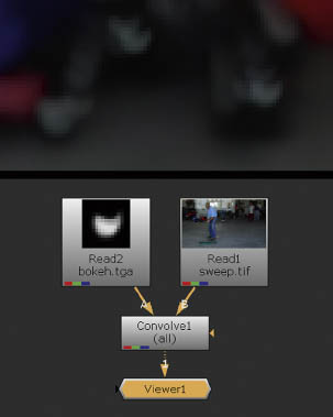
FIGURE 6.17 Close-up of background detail blurred with a Convolve node. Small, bright areas take on a U shape, as defined by a bitmap connected to the Convolve node’s input A. A sample script is included as convolve.nk in the Chapters/Chapter6/Scripts/ directory on the DVD.

FIGURE 6.18 A zoom blur is created with the DirBlur node. A sample script is included as dirblur.nk in the Chapters/Chapter6/Scripts/ directory on the DVD.
Motion Blurring
As discussed in previous chapters, you can activate motion blur through a Transform node’s Motionblur parameter. If the transform properties of the node are animated over time, a motion blur steak appears. You can also create motion blur with MotionBlur2D and VectorBlur nodes (found in the Filter menu). For example, in Figure 6.19, a motion blur is added to a bitmap with an animated Transform node. The MotionBlur2D node carries two input pipes. The 2DTransf pipe accepts motion vector channels. When 2DTransf is connected to a Transform node, forward.u and forward.v channels are passed to the MotionBlur2D node. The second input pipe, which is unlabeled, accepts the input that is to be blurred. In Figure 6.19, the unlabeled input is connected through a dot so that the pipe remains visible. The MotionBlur2D node carries Shutter and Shutter Offset properties that are identical to those carried by the Transform node. Shutter determines how long the virtual shutter is open. If shutter is set to 0.5, the shutter is open for a half frame. Shutter Offset determines when the shutter opens. If Shutter Offset is set to Start, the shutter opens on the current frame, which is identical to the way a real-world camera functions. By default, the MotionBlur2D node’s Output UV parameter is set to Motion; nevertheless, forward.u and forward.v channels are output by the node.
To convert the MotionBlur2D node’s output to an actual blur, the output is connected to a VectorBlur node. The VectorBlur node’s UV Channels parameter is set to Motion. Multiply scales the motion vector channel values.

FIGURE 6.19 Motion blur is added to an input with MotionBlur2D and VectorBlur nodes. A sample script is included as motionblur2d.nk in the Chapters/Chapter6/Scripts/ directory on the DVD.
The larger the Multiply value, the longer the blur streak becomes. If the VectorBlur node is connected to a MotionBlur2D node, Multiply scales the shutter duration set by the MotionBlur2D node’s Shutter parameter. Offset further offsets when the shutter opens. The MotionBlur2D node uses two forms of blur calculation, as set by the Method parameter: Backward and Forward. The Method names refer to algorithms and do not refer to the specific motion vector channels passed to the node. The Backward method is efficient while producing a good result. The Forward method is more accurate but is extremely slow.
Alternatively, the VectorBlur node can accept motion vector channels from imported sources. For example, in Figure 6.20, a Maya-rendered OpenEXR image sequence that carries RGBA as well as custom motion vector channels is imported through the Read1 node. To transfer the custom motion vector channels to forward UV channels in Nuke, the output of the Read1 node is connected to a ShuffleCopy node (Figure 6.21). The resulting motion blur is created solely within Nuke. For a comparison of Backward and Forward method algorithms, as well as an additional working example of the VectorBlur node, see Tutorial 5, “Adding Motion Blur to a CG Render” in Chapter 7.
The FurnanceCore plug-in set includes the F_MotionBlur node (The plug-ins appear in the Furnace or the FurnanceCore menu, depending on which version of Nuke you are running.) F_Motion-Blur uses motion estimation (tracking pixel value movement across multiple frames) to produce motion vectors. As such, the node is able to add additional motion blur to objects that are moving within an image sequence or movie. It requires a single input through the Src pipe. The Shutter Time parameter sets the virtual shutter duration in frames while the Shutter Samples parameter sets the number of in-between images the node used to produce the motion blur streaks. The node provides optional input pipes for per-calculated motion estimation vectors and an alpha matte used to separate foreground and background objects.
For more information on the F_MotionBlur node, see the “User Guide for Furnace” PDF available at The Foundry’s website (www.thefoundry.co.uk).

FIGURE 6.20 A VectorBlur node creates motion blur by reading the custom motion vector channels of an OpenEXR image sequence rendered in Maya. Note that the presence of custom channels is indicated by the dark green line at the far right of the node icons. A sample script is included as motionimport.nk in the Chapters/Chapter6/Scripts/ directory on the DVD.
The MotionBlur3D node can produce similar motion blur for 3D objects animated within Nuke’s 3D environment. This node is discussed in Chapter 9.
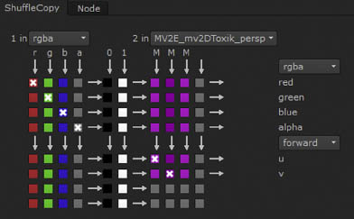
FIGURE 6.21 Custom motion vectors channels, stored under the MV2E_mv2DToxic_persp channel layer name, are transferred to the forward.u and forward.v channels with a ShuffleCopy node.
Sharpening
Nuke’s Sharpen filter, in the Filter menu, makes an input less blurry. The node achieves this by applying a Laplacian edge detection and separation filter, blurring the result, and subtracting it from the original input. (This method is often referred to as an unsharp mask.) This results in higher contrast along edges and other small details. The Size and Filter parameters control the intensity and style of blur. The Amount parameter controls the intensity with which the blurred copy is subtracted from the original values. High Amount values create a sharper, higher-contrast result. The Minimum and Maximum parameters control the value range targeted by the Laplacian filter. If the value difference between Minimum and Maximum is small, fewer edges are separated. Note that the Sharpen node only varies from the Soften node in that it subtracts the blurred edges instead of adding them.
Light Effects
In general, camera lenses are complex structures composed of multiple glass elements. When bright light sources are placed in front of a camera, glints, flares, and glows may appear due to the optical nature of the lens. A glint is an intense specular highlight that briefly appears as a surface moves relative to the camera. For example, sunlight glints off a rolling ocean. A glint will take on a shape specific to the lens setup. For example, a glint may appear star-shaped. In contrast, a lens flare occurs when an intense light source strikes the lens in such a way as to partially obscure the subject. The shape of the flare is dependent on the construction of the lens. In the realm of photography, a glow refers to a radiant light that surrounds a brightly lit object. The glow occurs when light bounces off the object and in turn reflects off smoke, fog, or dust particles suspended in the air (the particles are referred to as participating media). A similar effect occurs when light scatters within the camera optics or through the various layers found within motion picture or still photography film stock (although this is referred to as halation). Nuke provides several nodes through the Draw and Filter menus to create glints, flares, and glows. These are described in this section.
Glint, found through the Draw menu, places star-shaped highlights over bright pixels within an input (Figure 6.22). Each highlight will remain fixed unless the input changes with each frame. If there is significant change in the input, the highlights appear to sparkle. The No. Of Rays, Length, Aspect Ratio, Odd Ray Length, and Rotation parameters determine the appearance of each highlight. You can control where the highlights appear by preprocessing the input with the Tolerance and Gamma parameters. Lower Tolerance values create a greater number of highlights. You can mask the input and thereby choose the areas in which the highlights appear by connecting an alpha matte to the node’s Mask input. To use the mask, you must select the W parameter checkbox and choose the appropriate alpha matte channel through the corresponding menu. You can tint the input, and thereby change the highlight color, by changing the From Color value.
Flare, found through the Draw menu, creates a polygonal shape that represents a lens flare created by a single lens element (as opposed to an After Effects or Photoshop flare, which contains a string of polygonal shapes that represent multiple lens elements). Although the flare is round be default, you can flatten and adjust the edges through the node’s Shape section. You can interactively place the flare by LMB-dragging the Position handle. The Size is set by the Radius parameter, which is broken into inner, middle, and outer ring cells. The area between the inner and middle rings is filled with the color set by the Inner Color parameter. The area between the middle and outer rings is filled with the color set by the Ring Color parameter.
Glow, found in the Filter menu, isolates bright areas of an input, blurs and color corrects the isolated areas, and adds the result back to the original input (Figure 6.23). The Tolerance parameter sets a threshold for the isolation of bright areas. Higher Tolerance values reduce the areas to only the brightest sections of the input. The Brightness parameter sets the intensity with which the blurred areas are added to the original input. The Tint and Saturation parameters allow you to adjust the color of the blurred areas.
Sparkles, found in the Draw menu, creates a single star-shaped glare. You can interactively position the glare by LMB-dragging the Position handle. The glare is not affected by the input image. Instead, its qualities are controlled solely by the properties in the node’s Shape and Color sections. The glare will not change shape unless you manually animate the various properties.

FIGURE 6.22 Close-up of star-shaped glints created with a Glint node. A sample script is included as glint.nk in the Chapters/Chapter6/Scripts/ directory on the DVD.
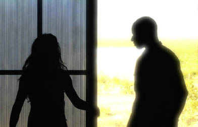
FIGURE 6.23 The Glow node is applied to a backlit image. Note that the glow effect removes detail from the brightest areas of the frame. A sample script is included as glow.nk in the Chapters/Chapter6/Scripts/ directory on the DVD.
Other real-world light effects are created when light strikes participating media. For example, when the reflected light rays are shadowed by such objects as clouds or tree branches, they create visible light beams or “god rays.” Nuke’s GodRays and VolumeRays nodes allow you to create such beams. Both are found in the Filter menu.
GodRays averages together multiple copies of the input with each copy offset by values set by the Translate, Rotate, Scale, and Skew parameters. The offset occurs from the center point, which you can set by interactively moving the Center handle in the Viewer. The Translate handle determines the general direction of the copies and the resulting streaking. Used as is, the GodRays node creates a motion blur effect. However, if the node is combined with merges, masking, transformations, and/or color correction, you can emulate god rays produced when the sun or other bright light is shadowed within a participating media, such as water vapor (Figure 6.24).
VolumeRays creates traditional god rays by sampling an input. The center of the effect is set by the Vol_Pos handle. The number and length of the rays is set by the Volume Options section. By default, the rays flicker.
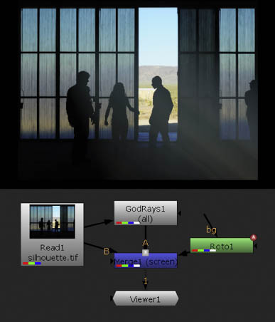
FIGURE 6.24 The GodRays node streaks an image. When combined with other nodes, such as Merge and Roto, a god rays effect is achieved. A sample script is included as godrays.nk in the Chapters/Chapter6/Scripts/ directory on the DVD.
However, you can control the flicker speed and flicker granularity through the Use Flickering section. The node destroys the input image; however, you can combine it with the original input through an additional Merge node.
Light Wrap
When an object is placed in front of a bright background, bounced ambient light “wraps” around the object edges. You can recreate this wrap with Nuke’s LightWrap node (Figure 6.25). The node operates by detecting the alpha matte edge of a foreground element, blurs the separated edge, uses the result to sample the background, and places the result over the foreground. The node’s input B accepts the background and input A accepts the foreground. The Diffuse parameter sets the softness of the blur and Intensity controls the intensity with which the blurred edge is added to the original foreground. The color and intensity of the background affect the color and intensity of the blurred edge. To create a consistently bright light wrap, you can select the Disable The Luminance Based Wrap parameters. You can force the blurred edge to extend past the alpha matte edge by selecting the Enable Glow parameter. You can adjust the Saturation parameter to alter the namesake quality of the edge blur. The FGBlur parameter further softens the blurred edge, while BGBlur blurs the background input before readding the edge to the foreground. If you prefer to add a solid-colored light wrap, select the Use Constant Highlight checkbox and set the color through the Constant slider. By default, the node adds the blurred edge to the foreground, but you can select a different mathematical merge operation through the Highlight Merge operation. If you’re curious what the light wrap looks like on its own, select the Generate Wrap Only checkbox.
Adding Noise and Grain
Motion picture film stock is dependent on silver halide grains embedded within the film emulsion. The grain is visible when the film is projected and is thus an inherent part of the medium. Video, whether it’s analog or digital, is subject to shot noise (1-pixel fluctuations in color). In addition, digital video suffers from compression artifacts (irregular noise patterns caused by the lossy nature of compression schemes). Hence, compositors often find a need to add grain and noise to elements within a composite to keep the output consistent with film or video. Nuke provides the following nodes through the Draw menu to fulfill this need.
Grain adds a synthetic film grain to the input. The node requires that the input carry an alpha channel. You can choose a specific motion picture film stock through the Presets parameter menu. You can adjust the size, color, and regularity of the grains through the namesake sections for each color channel.
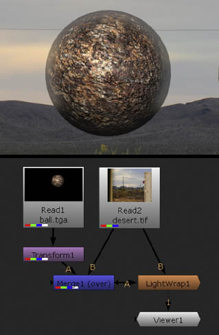
FIGURE 6.25 A LightWrap node recreates light bounce along the upper edges of a CG render of a sphere. A sample script is included as lightwrap.nk in the Chapters/Chapter6/Scripts/ directory on the DVD.
ScannedGrain applies grain to an input by referencing an image sequence. The sequence is loaded through the node’s Grain parameter. The intensity of the added grain per channel is set by the Amount R, G, and B cells. The node provides an interactive graph to fine-tune the contribution of the grain based on the intensity of the input pixel’s red, green, and blue values. Although the ScannedGrain node is designed to add motion picture film grain, you can use it to add video compression artifacts or shot noise to an input (Figure 6.26). You can prepare a grain/noise image sequence with the following steps:
The Nuke FurnaceCore plug-in set includes the F_ReGrain node, which allows you to add grain to an input. You can use one of the Preset Stock options to create a synthetic grain based on a specific motion picture film stock. You can also connect a grain source to the node’s Grain input pipe. If the Grain input is connected and the Preset Stock is set to Sample Grain, a sample box is drawn in the Viewer and represents the area in which grain is sampled. You can interactively move the box; for optimal quality, position the box over an area that contains a minimal amount of color and luminance variation as well as object detail. (To avoid unwanted color and luminance variation, prepare a grain source following the steps laid out in the section for the ScannedGrain node.) The Advanced section allows you to adjust the intensity of scale of the added grain per color channel.
For more information on the F_ReGrain node, see the “User Guide for Furnace” PDF available at The Foundry’s website (www.thefoundry.co.uk).

FIGURE 6.26 Video compression artifacts are added to an input with a ScannedGrain node. A sample script is included as scannedgrain.nk in the Chapters/Chapter6/Scripts/ directory on the DVD.
1. Film or videotape a median gray card. Scan or convert the result into an image sequence. Two to three seconds is required to create random change in the grain pattern over time.
2. In Nuke, blur the image sequence and subtract the result from the original sequence. Add 0.5 to the resulting RGB. Write the final output as an Exr sequence (Figure 6.27).
Noise creates a procedural fractal noise pattern. You can use the output as a mask. For example, a Noise node is used as part of Part 3 of Tutorial 2 as featured in Chapter 4. Alternatively, you can create shot noise by reducing the X/Y Size value. The noise pattern is three dimensional. Thus, you can “move through” the noise by changing the Z parameter value. The Octaves parameter determines the number of noise functions that are added together to create a more complex pattern; for example, setting Octaves to 2 will layer two noise functions, each with a different scale. The Lacunarity parameter controls the gap between various noise frequencies; higher values create a smaller noise pattern.

FIGURE 6.27 Video footage capturing compression artifacts is prepped for the ScannedGrain node with a specialized network. The network writes out as an Exr sequence. A sample script is included as grainprep.nk in the Chapters/Chapter6/Scripts/ directory on the DVD.
Removing Grain and Dust
Occasionally, film grain, film dust, video compression artifacts, and video shot noise become undesirable. Hence, Nuke provides DegrainSimple, DegrainBlue, TemporalMedian, and DustBust nodes, as described here.
DegrainSimple (in the Filter menu) averages the red, green, and blue channels through separate convolution blurs and thus softens small detail such as noise. The blur intensity is set by the R Blur, B Blur, and G Blur sliders.
DegrainBlue (in the Filter menu) operates in the same manner as DegrainSimple, but only targets the blue channel, which generally holds heavier grain for motion picture film. The intensity of the blur is set by the Size parameter.
TemporalMedian (in the Time menu) is designed to remove grain and noise by replacing the current value of each pixel with the median pixel value of the current, previous, and next frame. You can also use the node to reduce buzzing, stairstepping, and similar aliasing artifacts present in CG renders.
DustBust (in the Draw menu) allows you to clone small areas of a frame to cover bits of dust or other small imperfections created during the cinematography or videography. To use the node, follow these steps:
1. Connect the output you want to touch up to the input of the DustBust node.
2. Cmd/Ctrl+Opt/Alt-click a dust spot in the Viewer. A small white “dust bust” box appears. Cmd/Ctrl-drag the box’s center dot and release the mouse over a part of the screen you want to clone. For example, if you are removing a dust spot that occurs over the sky, Cmd/Ctrl-drag the dot to a clean part of the sky. When you release the mouse, a cloned spot covers the dust (Figure 6.28). You can scale the box up or down by LMB-dragging a box corner.
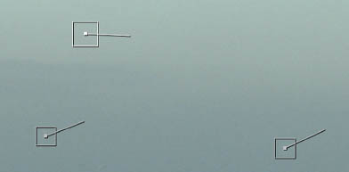
FIGURE 6.28 The boxes of a DustBust node cover dust spots with cloned areas of the frame. A sample script is included as dustbust.nk in the Chapters/Chapter6/Scripts/ directory on the DVD.
3. You can soften the edge of the cloned area by reducing the node’s Edge Hardness value. If you are working with an image sequence from a movie, you can clone a different frame by changing the Frame Offset. If the Frame Offset is set to 0, the current frame is cloned.
4. You can add additional “dust bust” boxes by continuing to Cmd/Ctrl+Opt/Alt-click in the Viewer. Note that each box lasts one frame on the timeline.
NukeX provides the Denoise node through the Filter menu. Denoise averages pixels within each frame to reduce grain and noise. To use the node, follow these basic steps:
1. Connect the output you want to degrain to the node’s Src pipe. Set the node’s Source menu to Film or Digital to match the source type.
2. Interactively move the analysis region selection box in the Viewer. For optimal quality, position the box over an area that contains a minimal amount of color variation and object detail (e.g., a solid-colored wall, a sky, or a greenscreen).
3. The grain/noise is reduced. The aggressiveness of the removal is controlled by the DeNoise Amount parameter. You can fine-tune the removal of small, medium, and large grains through the Tune Frequencies section or target grain based on luminance through the Tune Channels section. To reintroduce sharpening to edges, raise the Sharpen value.
4. Optionally, you can connect a noise source to the Noise pipe. For example, a similar piece of footage might contain areas where the noise is less obstructed by object detail; therefore, the Noise pipe provides the Denoise node with a pattern that is more easily identified.
In addition, the Nuke FurnaceCore plug-in set includes F_DeGrain and F_DeNoise nodes. F_DeGrain is specifically designed to remove grain from a still image. The basic steps for its use are as follows:
1. Connect the output you want to degrain to the node’s Src pipe.
2. Change the Original Colour Space menu to match the color space of the original footage. For example, digital video footage is captured as sRGB and motion picture film is scanned as Cineon.
3. Interactively move the green analysis region selection box in the Viewer. For optimal quality, position the box over an area that contains a minimal amount of color variation and object detail (e.g., a solid-colored wall, a sky, or a greenscreen).
4. The grain/noise is reduced. The aggressiveness of the removal is controlled by the DeGrain Amount parameter. You can fine-tune the removal of small, medium, and large grains through the Frequencies section or target grain in a specific color channel through the Channels section.
F_DeNoise also tackles noise and grain, but combines temporal averaging (averaging pixels across multiple frames) with motion estimation. F_DeNoise carries many of the same parameters as F_DeGrain and requires the same basic steps to employ it.
However, F_DeNoise adds the Plate Size parameter, which must be set to the resolution of the original footage (prior to any cropping or scaling). In addition, the F_DeNoise node provides Vec and Noise inputs. The Vec input accepts motion estimation vectors created from the footage in a step external to the F_DeNoise node; such a connection will speed up the node’s calculation. The Noise input works in the same fashion as it does for the Denoise node.
The FurnaceCore plug-in set also includes F_DeFlicker2. The node attempts to remove luminance flickering, such as that created by a flickering light bulb. The Deflicker Amount parameter controls the aggressiveness of the removal while the Analysis Range determines how many surrounding frames are examined to identify the flicker.
For more information on the F_DeGrain, F_DeNoise, and F_DeFlicker2 nodes, see the “User Guide for Furnace” PDF available at The Foundry’s website (www.thefoundry.co.uk).
Stylistic and Test Filters
Nuke provides several filters, in the Filter menu, that create stylistic effects. These include Laplacian, Emboss, BumpBoss, and Median.
Laplacian applies its namesake. As discussed in the section “Blurring and Convolution Filters” earlier in this chapter, a Laplacian filter separates high-contrast edges. The node achieves this by blurring the input and subtracting the original from the result. The Size parameter sets the size of the blur filter. The smaller the Size value, the smaller and thinner the separated edges are. Note that the node does not affect the alpha channel. The nonedge areas are left black.
Emboss creates the illusion of 3D bumpiness by offsetting high-contrast edges isolated within the input. By default, the node places the emboss effect over a gray background. However, you can add the emboss effect to the original input by switching the Emboss Type parameter to Effect. The direction of the virtual light is controlled by the Angle parameter. (The 3D quality is emulated by offsetting a bright and dark copy of the isolated edges; hence, there is a virtual highlight and virtual shadow for each “bump.”)
BumpBoss creates an embossed effect but uses input A to distort input B. The size of the bump detail is set by its namesake parameter. The intensity of the bump is set by the Line Height. You can interactively direct the virtual light by moving the Center and Light Position handles in the Viewer.
Median applies a form of convolution filter that replaces the input pixel value with a value that represents a median of surrounding pixels. That is, the pixel values in the kernel area are sorted and the middle value is selected. This blurs low-contrast areas while maintaining sharp edges along high-contrast transitions. The Size parameter sets the filter size. Small Size values allow small detail to survive, while large Size values simplify the input, creating a painterly result (Figure 6.29).
In addition, Nuke provides several filters that create specific 2D art suitable for testing various networks (these are found in the Draw menu). The Constant node produces a solid color and can serve as a temporary sky or a backdrop to test the success of a keying filter. You can employ the CheckerBoard node to see the results of a particular filter more clearly. The ColorBars and ColorWheel nodes create patterns that are ideal for testing monitor calibration.
Creating Custom Convolutions
Nuke’s Matrix node allows you to create your own custom convolution filter. When you choose Filter > Matrix, the Enter Desired Matrix Size dialog opens. Once you enter Width and Height values, the node is created. At that point, you are free to enter values into the matrix cells, which represent the values of the convolution kernel matrix that is slid over the input image. When working with positive matrix cell values, it’s often desirable to select the Normalize checkbox. Normalize divides the matrix result by the sum of the matrix values; this allows the output to retain the same brightness as the input. Figure 6.30 illustrates a 5 × 5 matrix with values that emulate a Gaussian blur. For additional matrix examples, see Tutorial 4, “Creating Custom Convolution Filters,” at the end of this chapter. Note that the size of the matrix relative to the resolution of the input affects the intensity of the filter. In other words, a small matrix has little impact on a large-resolution input.

FIGURE 6.29 A painterly effect is created with a Median node with the Size parameter set to 15. A sample script is included as median.nk in the Chapters/Chapter6/Scripts/ directory on the DVD.

FIGURE 6.30 A 5 × 5 convolution matrix created with a Matrix node. The values emulate a Gaussian blur. A sample script is included as matrix.nk in the Chapters/Chapter6/Scripts/ directory on the DVD.
Tutorial 3: Removing an Imperfect Greenscreen
Part 2: Applying Filters for Better Integration
In Part 1 of this tutorial, we keyed the greenscreen and rotoscoped the nongreenscreen areas to place the dancers with a new background. In Part 2, we’ll add filters to create a more believable and aesthetic integration.
1. Open the Nuke script you saved after completing Part 1 of this tutorial. A sample Nuke script is included as Tutorial3.1.nk in the Tutorials/Tutorial3/Scripts/ directory on the DVD.
2. Select the Transform1 node and choose Color > ColorCorrect. Refer to Figure 6.31 for the final node network. Open the new ColorCorrect1 node’s properties panel. Click the 4 button beside Master Gain. Enter 0.6 into the G cell and enter 0.4 into the B cell. This reduces the green and blue intensity of the plate and thus gives the dancers a yellowish cast that better matches the new background.

FIGURE 6.31 The final node network for Tutorial 3.
3. Select the Read2 node and choose Filter > Defocus. In the Defocus1 node’s properties panel, set the Defocus parameter to 8. This blurs the background. Small detail takes on a circular shape, which matches an out-of-focus real-world lens. A blurred background also matches a real-world, low-light-level shoot where a narrow depth of field is necessary to expose the film or video.
4. Select the Defocus1 node and choose Channel > Shuffle. Select the Shuffle1 node and choose Draw > Grain. Note that an error message appears in the Viewer. The Grain1 node requires an alpha channel to function. Open the properties panel for the Shuffle1 node. Select the box in the 1 column and the alpha row. This adds an opaque alpha channel to the output. The Grain1 node now functions. Open the Grain1 node’s properties panel. Reduce the Red, Green, and Blue values in the Intensity section until the added grain is very subtle. Because the background is a static bitmap, an added grain will better match the greenscreen plate. Although the plate was shot with a video camera, the video contains subtle, shifting shot noise and compression artifacts.
5. Select the Grain1 node and choose Color > ColorCorrect. Open the ColorCorrect2 node’s properties panel. In the Master section, increase the Contrast and reduce the Gain until the black areas of the background better match the black area of the female dancer’s hair. Matching the “blacks” within the various elements helps to make the composite more convincing (Figure 6.32).
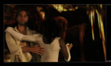
FIGURE 6.32 The final composite. Blur and grain is added to the background, while both the background and foreground are color balanced to better match.
6. Choose the Merge1 node and create a test render by choosing Render > Flipbook Selected from the menu bar. Continue to adjust the various filter nodes, including those used to key the greenscreen and adjust the matte edge, until no more improvement can be made.
This concludes Tutorial 3. As a bonus step, arrange the nodes, apply Backdrops, and add Dots to create a neat and organized node network. A sample Nuke script is included asTutorial3.final.nk in the Tutorials/Tutorial2/Scripts/ directory on the DVD.
Tutorial 4: Creating Custom Convolution Filters
Tutorial 4 takes you through the steps needed to create several custom convolution filters with the Matrix node.
1. Create a new Nuke script. Create a new Read node and import a bitmap or image sequence that will serve as a test bed for custom convolution filters. You can use any of the bitmaps included on the DVD. Note that it will be easier to see the result of a matrix with a smaller resolution image.
2. Choose Filter > Matrix. In the Enter Desired Matrix Size dialog box, enter 3 for the Width and Height. Connect the new Matrix node to the output of the Read node. Connect the output of the Matrix node to a Viewer.
3. In the Matrix node’s properties panel, enter the following values into the matrix cells:
![]()
This creates a Laplacian edge detection filter (Figure 6.33). In this case, the Normalize checkbox is left unselected.
4. Update the matrix cells with the following values:

FIGURE 6.33 The result of a Laplacian matrix.
![]()
Select the Normalize checkbox. This creates a “tent” blur filter (Figure 6.34).
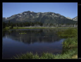
FIGURE 6.34 The result of a tent blur filter matrix.
5. Update the matrix cells with the following values:
![]()
Leave the Normalize checkbox selected. This creates a sharpen filter (Figure 6.35).
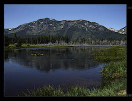
FIGURE 6.35 The result of a sharpen filter matrix.
This concludes Tutorial 4. A sample Nuke script is included as Tutorial4.final.nk in the Tutorials/Tutorial4/Scripts/ directory on the DVD. The sample script includes all three matrix variations.