
|
|
|
|
Keying |
|

Professional compositors often find it necessary to remove bluescreen or greenscreen from a live-action plate. Fortunately, a host of tools have been developed for such a task. The tools are generally called chroma keyers, as they target specific colors. You can use chroma keyers in a wide variety of ways to generate alpha mattes and thus impart transparency to a bitmap or image sequence that carried no alpha channel to begin with.
This chapter includes the following critical information:
• Chroma key basics
• Simple Nuke keyers
• Advanced Nuke keyers
Chroma Keying
Chroma keying is a critical part of professional compositing. As a process, chroma keying creates an alpha matte by targeting a specific color within a piece of film or video footage. This is necessary when shooting live action that utilizes a greenscreen or bluescreen. The screen may take the form of specialized fabric or a studio wall painted a specific shade of green or blue.
Although green and blue are the most common colors used for chroma keying, it’s possible to use chroma key compositing tools to target other colors, such as black or red. In fact, you can use the tools to target colors in nature. For example, you can target the color of a sky, whether it’s blue, gray, or orange.
Creating an alpha matte with a chroma key tool is called keying whereby the chroma key color is keyed out or keyed. The tools themselves are called keyers. Nuke offers eight keyers through the Keyer node menu. The part of the image you are trying to remove is often referred to as the background. The color of the background is often called the screen color, usually in reference to greenscreen or bluescreen. The part of the image you are trying to maintain is often referred to as the foreground. Spill represents background color that has reflected onto the foreground. For example, the green of a greenscreen may reflect onto an actor’s white shirt.
Simple Keyers
You can break Nuke’s keyers into two categories: simple and advanced. You can apply the simple keyers rapidly; however, they have a limited number of parameters with which to adjust the result. The Difference, Keyer, IBKGizmo, IBKColour, and HueKeyer nodes fall into this category. These nodes are discussed in this section.
Difference compares two inputs. Where the inputs carry identical pixel values in the RGB channels, the alpha matte is assigned a value of 0. Where the inputs carry different values, a value from 0 to 1 is assigned based on the degree of difference between the pixel values. The Difference node’s input A is designed to accept a clean plate, which is a version of input B that lacks the foreground elements. For example, a clean plate may be created by shooting two shots with a locked-off camera. The first shot includes an actor and becomes input B. The second shot is missing the actor so that only the background remains; this becomes input A. For example, in Figure 5.1, a bitmap featuring the close-up of an actress is connected to input B, while a bitmap featuring the same background without the actress is connected to input A. The resulting matte removes the background and the whitest part of the hat (which carries values similar to the background). If the A and B inputs are reversed, the background is cut out in the shape of the actress’s face.
The Difference node has two parameters, Offset and Gain. Offset darkens the resulting matte, while Gain brightens the resulting matte. In Figure 5.1, Offset is set to 0.15 and Gain is set to 3. Note that a Premult node is connected to the output of the Difference node. To use the alpha matte as part of a downstream process, such as a merge, the Difference node’s output requires premultiplication.

FIGURE 5.1 A Difference node is used to separate the face of an actress from a background. A sample script is included as difference.nk in the Chapters/Chapter5/Scripts/ directory on the DVD.
Keyer provides standardized methods of creating an alpha matte based on color, luminance, or saturation. The mode of operation is set by the Operation menu. Targeted values are controlled by an interactive range graph. With the graph, the bottom-left yellow bar (the A handle) sets the low end of the range (Figure 5.2). The top-right yellow bar (the B handle) sets the high end of the range. You can LMB-drag the A, B, C, and D handles. The C handle is revealed at the top right when the B handle is moved left. The D handle sits at the bottom right. Pixels with values to the left of the A handle are assigned a 0 (100% transparent) alpha matte value. The range between the B and C handles determines which pixels are assigned a 1 (100% opaque) alpha matte value. The range between the A and B handles establishes the taper at the matte edge; a greater slope between A and B produces a more gradual transition from transparency to opaqueness. The C and D handles allow you to offset the range that targets the foreground element (the part that receives a 1 alpha matte value). For example, if you move C and D handles to the left, the highest values within the input receive a 0 alpha matte value. In many cases, it’s not necessary to move the C and D handles to generate an acceptable result.

FIGURE 5.2 A range graph of the Keyer node. The A, B, C, and D handles are labeled.
As a working example, the black of a night sky is removed by moving the A handle to 0.0017 and moving the B handle to 0.01 (Figures 5.3 and 5.4). To create a softer edge transition, the B handle may be moved further to the right. To create a harder edge transition, the A handle may be moved to the same value as the B handle. In this example, the Operation menu is set to Luminance Key. Alternatively, setting the menu to a color option causes the node to target the intensity of a particular color channel (R, G, or B) or a specific screen color (green or blue). Setting the Operation to Saturation Key causes the node to target pixels with high saturation.
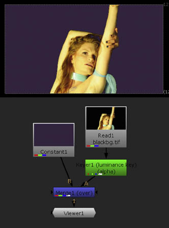
FIGURE 5.3 A Keyer node removes the black of a night sky. The result is merged with the purple of a Constant node.

FIGURE 5.4 A Keyer properties panel, as used for Figure 5.3. A sample script is included as keyer.nk in the Chapters/Chapter5/Scripts/ directory on the DVD.
IBKColour and IBKGizmo work in conjunction and are designed specifically for greenscreen and bluescreen removal. You can follow these basic steps when using the nodes:
1. Create an IBKColour node and a IBKGizmo node. Connect the output of the IBKColour node to the C input of IBKGizmo node.
2. Connect the input of IBKColour node, along with the Fg input of the IBKGizmo node, to the output you wish to key. Optionally, attach the Bg input of the IBKGizmo node to the output you wish to use as a background. See Figure 5.5 as a reference for the node network.
3. Connect a Viewer to the output of the IBKColour node. This node attempts to isolate the screen color by removing all other colors. Open the node’s properties panel. Change the Screen Type menu to Green or Blue to match the screen you are working with.
4. Connect a second Viewer to the output of the IBKGizmo node. This node takes the color information from the IBKColour node and creates the final alpha matte. Open the node’s properties panel. Change the Screen Type menu to C-Green or C-Blue to match the IBKColour nodes Screen Type menu. The screen color is removed from the output. If noise persists within the matte, return to the IBKColour node and adjust the Size parameter. Size controls the color range that the IBKColour node targets when isolating the screen color. For example, in Figure 5.5, Size is set to 0.
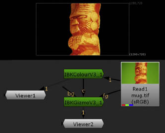
FIGURE 5.5 IBKColour and IBJGizmo are used to key a greenscreen. A sample script is included as ibk.nk in the Chapters/Chapter5/Scripts/ directory on the DVD.
You can use the IBKGizmo node without the IBKColour node by setting the node’s Screen Type menu to Pick and selecting a screen color through the Colour parameter.
HueKeyer identifies a screen color through an interactive graph. With the graph, hue is represented by the left/right X axis. The assigned alpha matte value for that hue is represented by the down/up Y axis. To use the HueKeyer, you can follow these basic steps:
1. Connect a HueKeyer node to the output you wish to key. Connect the output of the HueKeyer node to a Viewer.
2. Click the word “Amount” in the left column of the HueKeyer node’s properties panel. Note that two of the curve points are set at 1 in anticipation of working with greescreen or bluescreen. Pull these two points back down to 0 by LMB-dragging. You can also click a point, click the Y readout number, and enter 0 into the number cell.
3. Identify the X axis position of the color you wish to key by placing the mouse over the color in the Viewer. A yellow/white crosshair moves to the corresponding location in the graph. Insert a new curve point at the X axis location by Cmd/Ctrl+Opt/Alt-clicking the curve. Move the new point up to 1 in Y (Figure 5.6). To see the resulting alpha matte, press the A key while the mouse is in the Viewer. The identified hue is keyed out and the corresponding alpha values are reduced to 0 black. Note that the HueKeyer’s Invert parameter (at the bottom-right corner of the properties panel) is selected by default. This allows the Y axis values to be inverted; hence, the 1 values become 0 and 0 values become 1. To expand the hue range, insert additional points to the left or right of the new point, and move those up to 1. Interactively adjust the point positions in either the X or Y direction to refine the matte.
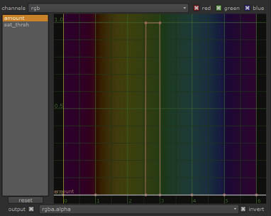
FIGURE 5.6 The graph of the HueKeyer node. Two of the Amount curve points are repositioned to 1 on the Y axis. The corresponding hues, which lie at 2.6 and 3 on the X axis hue scale, are thus targeted and are assigned a 0 alpha matte value. (The Invert parameter changes the 1 Y axis value to 0.)
4. To remove noise from the foreground matte, click the word “Sat_thrsh” in the left column. A new curve appears. Identify the hue of noisy areas by dragging the mouse in the viewer. The yellow/white crosshair moves in the graph. Add a new point at the X axis position and move the point up in Y. The higher the point gets, the less intense the noise becomes. The Sat_thrsh curve establishes the required degree of saturation a pixel must possess to be keyed out.
5. To use the alpha matte as part of a downstream process, such as a merge, connect the HueKeyer node’s output to a Premult node.
Beyond the interactive graph, the HueKeyer node offers no means to adjust the resulting matte. Hence, you may need to use additional filter nodes to address any remaining noise or rough matte edges. For example, in Figure 5.7, an Erode (Filter > Erode(Filter)) node is inserted between the HueKeyer and Premult nodes to soften the matte edge.

FIGURE 5.7 A greenscreen is keyed with a HueKeyer node. An Erode node is added to soften the alpha matte edge. A sample script is included as huekeyer.nk in the Chapters/Chapter5/Scripts/ directory on the DVD.
Advanced Keyers
Nuke’s advanced keyers were developed outside the program and are offered as plug-ins. Because the advanced keyers have enjoyed a long development cycle and heavy use within the visual effects industry, they provide a great deal of power and flexibility. Keylight, Ultimate, and Primatte fall into this category. Note that Ultimatte and Primatte are not available in the PLE version of Nuke.
Keylight uses a color difference methodology whereby all the colors within an input are compared to a single target color. The target color is defined by the Screen Colour parameter. When using the Keylight node, you can follow these basic steps:
1. Connect the Keylight node’s Source pipe to the output you wish to key. Connect the output of the Keylight node to a Viewer.
2. Select the color you wish to key by clicking the color swatch button beside the Screen Colour parameter so that the eyedropper icon appears. Sample pixels in the Viewer by Cmd/Ctrl-clicking or Cmd/Ctrl+Shift-dragging a selection marquee. Once a color is established, a key is created.
3. To examine the alpha matte, change the View parameter menu from Final to Screen Matte (Figure 5.8). To refine the matte, adjust the Screen Gain and Screen Balance parameters. Screen Gain determines the aggressiveness with which the screen color is removed to create the matte. Higher values cause a wider range of color values to be targeted. Screen Balance compares the intensity of the most intense color component of the screen color to the weighted average of the other two color components. For example, if you are removing a greenscreen, the green component is compared to the red and blue components; this process is applied to determine the relative saturation of the screen color of any given pixel. A Screen Balance of 0 forces the node to compare the primary component to the remaining component with the higher intensity. A Screen Balance of 1 forces the node to compare the primary component to the remaining component with the lower intensity. A Screen Balance of 0.5 compares the primary component to the two other components equally. Ultimately, different Screen Balance values create variations in the matte edge. Different screen colors require different Screen Balance values for optimum quality. (When the screen color is selected, the Screen Balance value is set automatically; however, you are free to change the value at any time.)

FIGURE 5.8 The Keylight node properties panel.
4. To make areas of the matte blacker or whiter, raise the Clip Black value or lower the Clip White value (in the Screen Matte section). Alpha matte values below the Clip Black value are clipped to 0 black. Values above the Clip White value are clipped to 1 white. To soften the matte edge, raise the Screen Softness value. To grow or shrink the 0-black area of the matte, adjust the Screen Dilate value. To restore lost edge detail, adjust the Clip Rollback parameter (this has no effect unless Clip Black and/or Clip White are set to non-default values).
5. If noise within the input is preventing the creation of a clean matte, you can raise the Screen Preblur parameter above 0. This preblurs the input and thus removes noisy pixels from the opaque portion of matte. However, high Screen Preblur values will create rounded matte edges.
6. To check the matte quality more carefully, switch the View menu to Status. Status presents an exaggerated view of the matte. Light green pixels represent problem areas where the screen color has been removed as spill and the corresponding matte is semi-transparent (Figure 5.9). If the adjustment of the aforementioned parameters fail to remove the green pixels, you can adjust the Screen Replace menu. By default, Screen Replace attempts to restore areas where screen color spill was present by using a color value defined by the Screen Replace Color parameter (which is black by default). If the Screen Replace menu is switched from Soft Colour to Hard Colour, the transitions at the edges of the replaced areas become rapid. If the Screen Replace menu is set to Source, the original colors of the unaffected input are utilized. Note that gray pixels within the Status view represent semi-transparency; however, they are not necessarily detrimental to the final alpha matte. Hence, it’s not necessary to create a Status view that’s composed of purely black and white pixels.
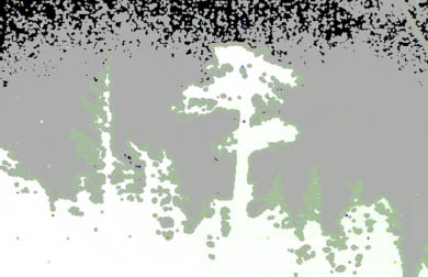
FIGURE 5.9 Close-up of a Status view. The light green pixels along the edge of a tree line represent problem areas where spill color is removed.
By default, the output of the Keylight node is premultiplied. However, you can create an unpremultiplied output by selecting the Unpremultiply Result parameter. The Keylight node carries three additional input pipes: Bg, InM (Inside Mask), and OutM (Outside Mask). To combine the keyed result with a new background, connect the Bg pipe to a suitable image and set the View menu to Composite. The InM input is designed to accept a holdout mask. A holdout mask restores a foreground element (a part of the image that should be 100% opaque). Holdout masks are useful when a foreground element is the same color as the screen color (e.g., green eyes match a greenscreen). The OutM input is designed to accept a garbage mask. A garbage mask quickly removes unwanted background objects, such as lights, camera rigs, greenscreen edges, and so on. The connected masks can take the form of a bitmap, bezier shape, or procedural texture. The InM Component and OutM Component menus (in the Crops section) determine whether the alpha matte information is derived from the mask’s alpha channel or the luminance information from the mask’s RGB channels.
A Keylight script is demonstrated in Figure 5.10. In this example, a sky is keyed from a bitmap featuring an off-season ski slope. Screen Colour is sampled from the bitmap and is set to cyan. Screen Gain is 1.05, Screen Balance is 0, Clip White is 0.58, Screen Softness is 0.1, and Screen Replace is set to Soft Colour.
Ultimatte uses color difference methodology, whereby all the colors within an input are compared to a single target color. However, Ultimatte offers a custom Viewer toolbar as well as a wide range of matte and spill adjustment parameters. When using the Ultimatte node, you can follow these basic steps:
For additional information on the Keylight node, see the “Keylight” PDF available at The Foundry’s website (www.thefoundry.co.uk).
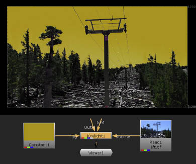
FIGURE 5.10 A sky is keyed out with Keylight. A sample script is included as keylight.nk in the Chapters/Chapter5/Scripts/ directory on the DVD.
1. Connect the Ultimatte node’s Fg pipe to the output you wish to key. Optionally, connect the Bg pipe to an output that you wish to appear as a background. Connect the output of the Ultimatte node to a Viewer node.
2. Click the Screen Color eyedropper button and Cmd/Ctrl-click or Cmd/Ctrl p Shift-dragging a selection marquee in the Viewer to sample the color you wish to key. The alpha matte is created and the Bg input appears. The Ultimatte node adds a toolbar to the top of the Viewer tab. You can use these controls to refine the matte (Figure 5.11).
FIGURE 5.11 The Ultimatte Viewer toolbar.
3. In the properties panel, switch the Overlay menu from Off to Screen. Semi-transparent red is overlaid in the Viewer. The red indicates the pixels that carry the screen color. Switch the Overlay menu to Subject. The red indicates the foreground pixels—that is, the pixels that do not carry the screen color (Figure 5.12). Note that semi-transparency of the alpha matte is not indicated by the overlay. You can add pixels to the Screen or Subject overlay by clicking the Overlay + button in the Primatte toolbar and Cmd/Ctrl-clicking or Cmd/Ctrl-dragging in the Viewer. You can also Cmd/Ctrl+Shift-drag a selection marquee. You can remove pixels from an overlay by clicking the Overlay – button. You can erode or expand the edge of the screen overlay by switching to the Screen Correct tab and adjusting the Shrink value. This may be useful for closing small holes that appear in the foreground section of the matte.
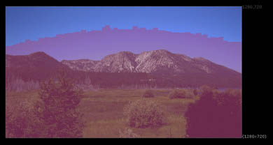
FIGURE 5.12 The Overlay menu, when set to Subject, tints pixels that do not carry the screen color. This display does not indicate any semi-transparency within the alpha matte. With this example, the blue of a sky is selected as the Screen Color.
4. To examine the alpha matte directly, press the A key while the mouse is in the Viewer. Gray pixels indicate semi-transparency. Switch to the Density tab (Figure 5.13). Adjust the Brights and Darks parameters. Brights adjusts the intensity of the most intense foreground pixels. Darks adjusts the intensity of the least intense foreground pixels. Interactively set the Brights and Darks parameters by clicking the Matte + or Matte − button in the Primatte toolbar and Cmd/Ctrl-clicking, Cmd/Ctrl-dragging, or Cmd/Ctrl+Shift-dragging. The + button adds additional pixels to the foreground matte (pixels with a value of 1). The – button removes pixels from the foreground matte (and thereby assigns a value of 0).

FIGURE 5.13 Ultimatte properties panel.
5. If the foreground suffers from the excessive presence of the screen color (having arrived as spill) or is unduly altered by the automatic removal of the screen color, switch to the Spill tab. Adjust the Cool and Warm parameters, which control the amount of the screen color present in the foreground in cool-color areas and warm-color areas. You can also adjust the parameters to aesthetically alter the foreground color balance. To make this adjustment easier, return the Viewer to an RGB view and switch the Overlay menu back to Off.
6. If you use the Matte + or Matte − button in the Ultimatte toolbar, the Enable parameter of the Cleanup tab is automatically selected. You can also activate the parameter manually. The Cleanup parameter removes noise contained within the screen color (background) area of the matte. The higher the value, the more aggressive the removal of noise. You can blur the matte edge by raising the Blur parameter.
7. To output a premultiplied or unpremultiplied result, switch back to the Ultimatte tab and change the Output Mode to the appropriate option.
The Ultimatte node includes two additional input pipes: Gm (Garbage Mask) and Cp (Clean Plate). The Gm input accepts its namesake mask (see the Keylight section for a description). The Cp input is designed to accept a clean plate. A clean plate is used by the Screen Correction process of the node to remove inconsistencies that appear in the screen color area. Such inconsistencies may be caused by wrinkles in the chroma key fabric, shadows, film grain, video compression noise, smoke, or similar elements. If the Cp input remains unused, the node synthesizes a clean plate by examining the Fg input. The synthesized clean plate is significantly less accurate than an actual clean plate but can be useful for reducing anomalies caused by film grain or video compression artifacts. (A plate is a specific piece of film or video footage that is captured as a single shot and is intended for visual effects work.) An example Ultimatte script is demonstrated in Figure 5.14. In this example, a sky is keyed from a bitmap featuring a mountain range and field. Screen Color is sampled from the bitmap and is set to light blue. Brights is set to 0.45, Darks is set to 126, and Blur is set to 4.7.
Primatte creates a key by generating a polyhedron shape within a 3D representation of the current color space. Pixels with values that fall within or on the shape are assigned transparency through the output alpha channel. The shape is established and altered by sampling pixels within the Viewer panel. To use Primatte, follow these basic steps:
1. Connect the Primatte node’s Fg pipe to the output you wish to key. Optionally, connect the Bg pipe to an output that you wish to appear as a background. Connect the output of the Primatte node to a Viewer node.

FIGURE 5.14 A sky is keyed out with Ultimatte. A sample script is included as ultimatte.nk in the Chapters/Chapter5/Scripts/ directory on the DVD.
2. Open the Primatte node’s properties panel. Click the Current Color button (below the Operation menu) so that the eyedropper icon appears. In the Viewer, Cmd/Ctrl-click or Cmd/Ctrl+Shift-drag to sample the screen color. A matte is created and some of the pixels in the screen area become transparent, revealing the Bg input.
3. To fine-tune the resulting matte, step through the Operation menu. Each menu option allows you to make additional pixels transparent or return opaqueness to pixels previously sampled. Regardless of the Operation menu setting, select pixels in the Viewer with the Current Color button and the Cmd/Ctrl-click or Cmd/Ctrl+Shift-drag mouse operations.
4. By default, the Output Mode menu of the Primatte node is set to Composite. This allows the Bg input to appear. However, once the matte is created and you would like to use the Primatte’s output in conjunction with another part of the network, you must change the Output Mode menu to Premultiplied or Unpremultiplied. Once one of these two settings is chosen, the Bg input is disabled.
For a more detailed step-by-step guide, see “Tutorial 3: Removing an Imperfect Greenscreen” at the end of this chapter.
The Cover Composite
The cover illustration for this book, featuring a dancer in front of a mirror that reflects the grand hallway of an ornate building, was created in Nuke (Figure 5.15). The source footage features the dancer against a partial greenscreen (Figure 5.16).

FIGURE 5.15 The composited cover image.
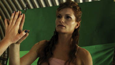
FIGURE 5.16 The unaltered greenscreen plate.
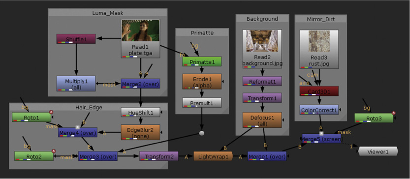
FIGURE 5.17 The node network used to create the composite. The backdrops indicate different sections of the network.
The node network is organized into several sections indicated by backdrop shapes (Figure 5.17). Following are brief descriptions of each network section.
Primatte. The greenscreen is removed using the Primatte plug-in. The resulting matte edge is softened with an Erode node. The result is premultiplied.
Luma_Mask. Because the Primatte node aggressively removes the fine hair detail of the dancer, a separate luma mask is created by copying the plate’s red channel to the alpha with a Shuffle node, increasing the contrast of the alpha with a Multiply node, and recutting the plate with a Merge node that lacks an input B.
Hair_Edge. The luma mask result is fine-tuned with a EdgeBlur node and a HueShift node. The HueShift node removes the green spill trapped in the fine hairs. The luma mask result is then combined with the Primatte result through an additional Merge node. Parts of the set that are not covered by the greenscreen are cut away with two Roto nodes.
Background. The background image, which is a static bitmap, is thrown out of focus with a Defocus node and is rescaled, rotated, and repositioned with Reformat and Transform nodes.
Mirror_Dirt. Semi-transparent dirt is placed in the foreground by converting a texture bitmap into a 3D card, rotating the card, and color correcting it.
Ultimately, the dancer, the background, and the dirt are combined through two additional Merge nodes. The area the dirt appears is limited by masks drawn with an extra Roto node; the dirt is kept semi-transparent by using a Screen merge operation. The final result is color graded with a Color Correct node. A sample Nuke script is included as cover.nk in the Chapters/Chapter5/Scripts/ directory on the DVD. (Please note that the background image and dirt texture are not included on the DVD due to copyright issues; however, you can replace the missing bitmaps with your own bitmaps through the empty Read nodes.)
Tutorial 3: Removing an Imperfect Greenscreen
Part 1: Keying with Primatte and Rotoscoping
Tutorial 3 takes you through the steps needed to remove a greenscreen (Figure 5.18).

FIGURE 5.18 A greenscreen setup that suffers from inconsistent color, shadows, and incomplete coverage.
The greenscreen suffers from the following problems:
• Inconsistent green color created by two different greenscreen fabrics.
• Wrinkles in the greenscreen, plus uneven lighting.
• Incomplete greenscreen coverage.
• Shadows from dancers on the greenscreen.
Nevertheless, using the Primatte keyer node, in addition to rotoscoping and using several additional filter nodes, provides a solution. (Note that Primatte is not available in the PLE version of Nuke; however, other keyers, such as Keyer or HueKeyer, are available.)
1. Create a new Nuke script. Choose Edit > Project Settings from the menu bar. In the Project Settings properties panel, set Full Size Format to 1280 × 720. If 1280 × 720 is not present in the menu list, choose New and enter the proper resolution in the New Format window.
2. Create a Read node. Browse for the Tutorials/Tutorial3/Plates/greenscreen/ directory and select the greenscreen.##.tga 1 30 image sequence. Connect Viewer1 to the Read1 node. The sequence features two dancers crossing in front of a greenscreen.
3. In the Node Graph, RMB-click and choose Image > Constant. Select the Read1 node, RMB-click, and choose Keyer > Primatte. Connect the Bg input pipe of the Primatte1 node to the output of the Constant1 node. Open the Constant1 node’s properties panel and change the Color to a hue that’s easily seen, such as red. The Bg pipe of the Primatte node allows you to add a background, which will show in the area where the greenscreen has been removed. This offers a convenient means to test the effectiveness of the greenscreen removal.
4. The Primatte node works in its default state. However, it will remove the area of the input that is black. Open the Primatte1 node’s properties panel (Figure 5.19). Click the Current Color button so that its eyedrop icon appears (the button is below the Operation menu). Place the mouse in the Viewer and Cmd/Ctrl-click over the greenscreen to sample the greenscreen color. You can also Cmd/Ctrl+Shift-drag to draw a selection marquee and thereby select a group of pixels to average. For this tutorial, it’s best to sample an area of the shadow to the left of the dancers as they pass. This ensures that the shadow is removed along with the more intensely bright areas of the greenscreen. As the green is removed, the green areas become semi-transparent or transparent. This allows the color of the Constant1 node to show through. Note that the green carried by the dancers’ skin tone and the background walls is partially removed at this point (Figure 5.20).

FIGURE 5.19 A Primatte properties panel in its default state.

5. In the Primatte node’s properties panel, change the Operation menu to Clean BG Noise. Cmd/Ctrl+Shift-drag selection marquees over areas of the greenscreen that are not fully transparent. For example, sample the lower right of the greenscreen, which contains brighter greens.
6. Change the Operation menu to Clean FG Noise. Cmd/Ctrl+Shift-drag selection boxes over areas of the dancers that have become transparent. This restores opaqueness to the dancers. You can restore all clothing and skin of the dancers without unduly altering the greenscreen area. Alter between Clean BG Noise and Clean FG Noise to produce the best result (Figure 5.21). You can reset the node at any time by clicking the Reset button beside the Algorithm parameter; however, you will have to reselect a color through the Current Color button. While adjusting the Primatte node, save the script on a regular basis. It can be difficult to back up to an optimal step in the process by simply using Edit > Undo or Cmd/Ctrl+Z. As you adjust the node, move the time marker to different frames of the timeline to properly judge the results.
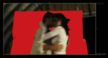
FIGURE 5.21 The key is improved by utilizing the Clean BG Noise and Clean FG Noise operations.
7. At this stage, green spill is trapped in the dancers’ clothing and skin tone. You can reduce this by switching the Operation menu to Spill(∓) and sampling the greenish area along the dancer’s white clothing. While you are adjusting the various parameters of the Primatte1 node, feel free to examine the alpha channel of the output. To do so, place the mouse in the Viewer panel and press the A key. Examining the alpha channel allows you to spot areas that remain semi-transparent (with values that are gray instead of black). You can return to the RGB view by pressing the A key again.
8. Once the greenscreen is removed, examine the edge quality of the resulting alpha matte. Due to the motion blur present in the video, along with native compression artifacts, the edge of the dancers appears rough and stairstepped. You can reduce this by adding an additional filter node. Select the Primatte1 node, RMB-click, and choose Filter > Erode (Blur). Open the Erode1 node’s properties panel. Note that the Channels menu is set to None and the right Additional Channels menu is set to Rgba.alpha. Thus, the RBG channels are unaffected by the node. With the Erode1 node selected, RMB-click and choose Merge > Premult. To use the Erode1 node successfully, its output must be premultiplied. Open the Primatte1 node’s properties panel. Note that the Output Mode menu, near the bottom of the panel, is set to Composite by default. This allows the Constant1 node to appear behind the image sequence. Switch the menu to Unpremultiplied. The constant color disappears. This step is also necessary to accurately gauge the Erode1 node’s influence. Open the Erode1 node’s properties panel. Adjust the Size and Blur parameters. Blur controls the size of a triangle convolution filter that averages the pixel values along the alpha edge and thus softens it (Figure 5.22). Higher values result in a wider, softer edge. Size shrinks the matte created by the Blur parameter, thus eroding it. For example, if Size is set to 5, the matte is eroded by five pixels. If Blur is a nonzero value, the taper from 100% transparency to 0% transparency remains soft. If you are unable to see the effect of a large Blur value, slowly raise the Size value.
9. The Erode1 node may erode the bottom edge of the matte. Thus, a gap opens up between the dancers and the frame edge. To quickly solve this problem, select the Premult1 node, RMB-click, choose Transform > Transform, and interactively move the dancers downward so that the gap disappears.
10. At this point, you can add a background image to make the composite more interesting. To do so, create a new Read node and import a bitmap or image sequence. A sample bitmap is included as cave.tif in the Tutorials/Tutorial3/Bitmaps/ directory on the DVD. With no nodes selected, create a Merge node. Connect the input A pipe to the output of the Transform1 node. Connect the input B pipe to the output of the Read2 node. The dancers appear over the new background image (Figure 5.23).

FIGURE 5.22 Close-up of the alpha channel. The matte edge is softened with the addition of Erode and Premult nodes.
11. At this stage, a portion of the set that was not covered by the greenscreen material remains visible. To remove the various parts of the building, you must rotoscope. You can apply the rotoscoping in two steps: a garbage mask to cut away the building and a second mask to restore the parts of the dancers that extend over the edge of the greenscreen. To create a garbage mask create a new Roto node (Draw > Roto), connect the output of the Read1 node to the Bg input of the Roto1 node, and connect a new Viewer to the output of the Roto1 node. After switching to the new Viewer tab, move the time marker to frame 1 and draw a closed shape that encompasses the building (Figure 5.24). Note that you can place points outside the bounding box. For more information on the Roto node and rotoscoping techniques, see Chapter 4. Move the time marker to frame 30. Adjust the shape. Because there is a slight left-to-right camera movement, two keyframe positions are necessary for the garbage mask.

FIGURE 5.23 The output of the Premult1 node is moved down in Y with the Transform1 node. This prevents the appearance of a gap along the bottom of the dancers. A background is added through the Merge1 node.
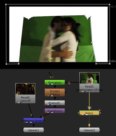
FIGURE 5.24 A bezier shape is drawn with a Roto node.
12. To convert the new shape into a functioning alpha matte, connect the output of the Roto1 node to the Mask input of the Merge1 node. Switch back to the Viewer1 tab. The dancers are cut out but the building remains. Open the Roto1 node’s properties panel. Select the Inverted button beside the Bezier1 curve in the Curves section. The button features a small box with a diagonal line. Once the Inverted button is selected, the matte is inverted and the building is cut away (Figure 5.25).
13. Play back the timeline. The dancers are cut by the garbage matte as they move past the edge of the greenscreen. To restore the dancers, you can apply additional rotoscoping. To do so, create a new Roto node, connect the output of Read1 to the Bg of Roto2, and connect the output of Roto2 to Viewer2. Switch to the Viewer2 tab. Move the time marker to frame 1. Draw a shape in the Viewer that covers the left side of the dancers. Once the shape is closed, it’s filled with solid white. If you’d like to see through the fill to the image sequence, temporarily set the Roto2 node’s Opacity parameter to 0. Alternatively, you can deselect the node’s Visible button (Figure 5.26). Adjust the point smoothness and point feather to match the contours of the dancers and the softness of the inherent motion blur. Move to a different frame, such as frame 5. Adjust the shape to match the dancers’ contours. The new point positions are automatically stored in a new keyframe. Continue to refine the shape over the course of the timeline.

FIGURE 5.25 The shape is converted into a matte by connecting the output of the Roto1 node to the Mask input of the Merge1 node. The Inverted button for the shape is activated in the Curves section of the Roto1 properties panel.

FIGURE 5.26 An additional shape is drawn to maintain the dancers as they move past the edge of the greenscreen. The Visible parameter for the shape is temporarily deselected so that the fill color does not obscure the image.
14. To utilize the alpha matte created by the Roto2 node, connect the output of Roto2 to the Bg input of Roto1. Such a connection adds the two alpha mattes together through an Over operation before sending the result to the Mask input of the Merge1 node. (The Opacity parameter of Roto1 and Roto2 must be set to 1 and the Visibility button of both shapes must be reactivated.) Switch to the Viewer1 tab to view the result (Figure 5.27). You can continue to refine the Roto2 shape. To make the bezier shape visible in the Viewer, open the Roto2 node’s properties panel.

FIGURE 5.27 The alpha mattes of Roto1 and Roto2 are combined by connecting the output of Roto2 to the Bg input of Roto1. As seen on frame 1, the dancers are no longer cut off by the Roto1 shape.
This concludes Part 1 of Tutorial 3. A sample Nuke script is included as Tutorial3.1.nk in the Tutorials/Tutorial3/Scripts/ directory on the DVD. In Chapter 6, we’ll adjust the keyed greenscreen and the background bitmap with various filters to create better integration.