
13.2. Following the Technology Engineering Steps
For the technology component, only the first two views require the combined effort of the business and IT teams as shown in Table 13-1.
| Business View | Technology View |
|---|---|
| Owner's Wants View | Business Locations |
| Owner's Needs View | Business Networks |
For each project, the business team focuses on just those locations that will be impacted by the new CRM functionality. Because this component is primarily the responsibility of Information Technology, we will look only at the top two business levels.
13.2.1. Owner's Wants View: Business Locations
During strategic planning, we identified a list of locations and high-level process. Many times during strategic planning, we used a matrix as a tool for understanding the relationship between two important topics (e.g., customer life cycle and touch points). Here is another important relationship that was understood and documented during strategic planning, the one between business functions and geographic locations, as shown in Figure 13-3.
Figure 13-3. XYZ's function/location matrix

For Valencia we know that two major functions were involved, S-800 Marketing and Telesales. Where are these functions located? From the organization map in Figure 13-1, we know that the S-800 Division, including the marketing organization, is located in Vancouver, British Columbia. With the help of the organization/function matrix in Figure 13-3, we see that telesales call centers are located in Tampa, Vancouver, and Guadalajara. The database itself was to be physically located in Chicago, so the key company physical locations that are important to the success of Valencia are Chicago, Guadalajara, Tampa and Vancouver. Of course, there are always options for reducing project scope by implementing in only one location. XYZ wanted to roll out all regions because most of these top 50 customers were located in multiple countries.
The function/location matrix acts as a roadmap for where different business organizations are located. At a very high level, Information Technology uses this matrix to understand the system access and network links that need to be in place to support information and work flow requirements of the business.
13.2.2. Owner's Needs View: Business Networks
Now we'll look at the business network for XYZ's first customer identity project (Valencia). The key business connection requirements for the project were also identified in Chapter 12: Database marketing sends an offer to the customer who dials the telesales call center to place an order. Telesales takes the order and sends it on to the factory that will build and ship the product to the customer.
The network connection requirements for Valencia are from the S-800 database marketing team to customers (not shown), from customers to one of the call centers, from the call center to the S800 factory, and from the factory to the customer to complete the transaction, as shown in Figure 13-4.
Figure 13-4. The Valencia business network
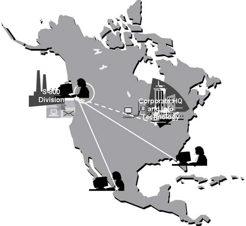
Although there are important project communications between the executive team, the corporate IT team and project team, these network links are not part of the project work. They have been indicated by a dashed line in Figure 13-4.
13.2.3. The Remaining Views
As we know, most of the responsibility for technology engineering rests with the IT department, which is responsible for developing each of the remaining views and for the final implementation and support of the functioning technology network. The three remaining views are based on the information, process, and physical location requirements that were identified in Chapters 11 and 12.
Designer's View: Distributed System Architecture
Using knowledge about what work needs to get done, where, and by whom (how many), the IT team can plan where to locate computer servers that will optimize business and application performance.
Builder's View: System Architecture
Current application software and connections (interfaces) between them result from the system inventory. The future system architecture will show the integration of new software (additions or replacements) and what new interfaces will be required. The system architecture is often shown in stages or phases such as the following:
Where we are today (created once during strategic planning)
What we will have after this project is completed
Where we plan to be when we're finished (created once during strategic planning, but updated as plans change)
Here's an example of XYZ's current system architecture, as well as what is planned to be in place when this project is finished. You can see the current and future states in Figure 13-5.
Figure 13-5. Valencia System Architecture
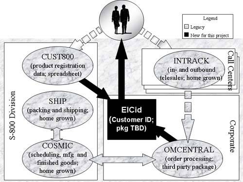
This system architecture shows that as a result of the Valencia project, a new system (El Cid) will be built or purchased and data from the order processing system and the S-800 product registration database will be loaded. The database marketers will select target customers from the El Cid database and send the offer. These are the new elements of the architecture. The rest of the applications and connections already exist (although some connections, as indicated by broken arrows, are manual or are only semi-automated). It is quite common to organize a System Architecture diagram by the organization that owns/operates each element. For each project, it will be important for the IT department to create a map of what the architecture will look like when the project is finished. This is just one more way of showing the progress that has been and will be made, and it's just as important for the IT team to show visible progress to their management as it is for the business functional members of the team.
Subcontractor's View: Network Architecture
Using all that has been planned about where work is to be done, where computers are located, and what people and systems need to talk with each other, Information Technology defines a network architecture showing all the network connections (including backup redundancy) that are required to support the system. The important thing is that the IT team has an overall plan and architecture that is guiding the development of your company's CRM solution.
By the way, there is another good way of describing the system architecture. The view in Figure 13-5 is organized around the company's organizational structure. The view in Figure 13-6 is from the perspective of what kind of work needs to get done, operational or decision-making activities.
Figure 13-6. System architecture
The benefit of this architectural perspective is that it emphasizes the difference between transaction processing applications and decisions support applications. The IT analysts need to design the two very differently, because transaction systems are tuned to capture and modify data about events that take place (orders, shipments, etc.) and decisions support applications are turned for searching, selecting, sorting, and summarizing the transaction data. Most of the elements of the traditional system architecture are located on the left side of this architecture. Having only the data needed to support a specific interaction optimizes transaction systems. There is a strong link between the transaction systems and the master reference files that capture and consolidate information that is to be shared across the various transaction systems (such as the customer information in the El Cid database). The CUST800 system would be located on the right because its main purpose is reporting, analysis, and market research. Many companies have created a central data warehouse that collects all the details of the transactions and master file changes over time so that trend analysis and reporting can occur. But this is too much data for almost any reporting tool to handle efficiently, so this architecture includes the creation of local copies of portions of the warehouse that are relevant to a specific function (e.g., marketing) or a specific decision (who are our most valuable customers).
At the end of all this work, for which the IT team is largely responsible, is the functioning network that connects all the system pieces together and supports sharing of information and work flows across the whole company.
13.2.4. The Transition to Information Technology
As we've learned, most of the responsibility for the technology component lies with the IT department. The handoff between business and Information Technology happens very early, during the development of the owner's view, as shown in Figure 13-7.
Figure 13-7. Technology handoff

Now we'll look at some of the considerations we have to make when we are ready to select a specific technology approach.