
D.4. Designer's View: Entities and Relationships
The Designer's View is where the handoff between business knowledge and IT knowledge takes place. Let's review the process that XYZ used to identify the entities, attributes, and relationships for Valencia.
Develop a list of the characteristics (attributes) we want to collect and store about each of the project data subjects; identify and eliminate duplicates.
Assign each attribute to the data subject it describes; these are candidate entities.
Identify the KEY for each candidate entity.
Apply entity rules to determine whether all the related attributes can be stored in one entity or whether we need to define more than one.
Identify entity relationships.
Define entities, attributes, and relationships.
First, we will identify the facts that are important to XYZ's efforts to recognize customers consistently.
D.4.1. Develop Attribute List
We discussed that one of the best sources for understanding what your company needs is to look at what you already collect and use for reporting and other purposes. Figure D-3 is the example we saw in Chapter 10 of one of XYZ's early product registration cards.
Figure D-3. XYZ's product registration card

We learned that each question on this card represents a characteristic or attribute of a single data entity. We just need to make a list of all these elements, and then assign them to the appropriate entity. Of course, we always start with the results of the previous step, the three data subjects: Installed Products, Customer Contacts, and Customer Companies.
D.4.2. Assign Attributes to Entities
To get started, XYZ first needed to define some entities. They didn't really know what all these should be at this point, so like previous steps, they used the data subjects from the previous view as candidate entities. The candidate entities then were Installed Product, Customer Contact, and Customer Company. By the way, a naming convention commonly used in information engineering uses the plural noun as names for the two highest level views (class and subject) and a singular form for the rest of the views. This book employs a convention for the hierarchy of views that for the “customer” is shown in Table D-7.
| Class | Subject | Entity | key | attribute |
|---|---|---|---|---|
| CUSTOMER | Customer Company Customer Contact | Customer Company Customer Contact |
The attribute assignment for each entity is the task that XYZ tackled next. Attributes were assigned to the entity it best described. The registration card asked for information about the product, the owner (customer contact person), and the customer company. XYZ had defined the data class INSTALLED PRODUCTS as “Products or services owned or used by a customer company or contact.” The candidate entity of the same name carries has the same definition. The product information on the registration card describes products owned by customers, so that was the appropriate place to assign the product facts. XYZ assigned the rest of the information to the appropriate customer entity (contact person and company) as shown in Table D-8. I told you it was easy!
Well, I'm sorry; it's not quite that easy. If you were browsing through a file folder to check for a product warranty on a specific installed product, you'd probably sort through just the documents for the right product and then check each serial number. Product model and serial number uniquely identify a product (whether installed or not). These identifying attributes are called the “unique key.” In a computer with its capacity for storing huge numbers of “forms,” it would be impossible to browse through them one at a time. The key is how the computer recognizes and retrieves exactly the right information. XYZ's next task was to choose a unique key for each entity.
D.4.3. Develop Entity Keys
Every entity must have a unique key. The key identifies a specific real customer (or employee or product); the customer must always have the same key, and the key can never represent any other customer—even if the customer goes out of business. In other words, keys must remain stable over time, and each must uniquely identify only one customer (employee, product). A key is one or more attributes that, in combination, uniquely identify each instance of the entity.
Installed Product
Let's look at how XYZ handled the Installed Product entity shown in Table D-6. They had to decide which attribute(s) might uniquely identify a single Installed Product. Having just discussed this issue, we understand why XYZ identified product and serial number as the unique key identifier of a specific product installation. XYZ chose product model + serial number as the unique key for the Installed Product entity as shown in Table D-9, which also includes the other entity attributes of this entity.
| Candidate Entity (Subject) | Attribute |
|---|---|
| Installed Product | product model serial number |
| purchase date | |
| where purchased | |
| store name | |
| store city | |
| store state | |
| used for | |
| where used | |
| competitive product 1 | |
| competitive product 2 | |
| competitive product 3 | |
| competitive product 4 | |
| competitive product 5 |
Next, XYZ did the same analysis for the other two candidate entities.
Customer Contact
At first glance, we might think a customer contact is identified by first and last name. But of course, names are not unique. However, XYZ decided that a name at a particular address (either street or e-mail address) was adequate to assume uniqueness for the purposes. (There is no right or wrong answer, just what makes sense for your situation—as long as it's unique, that is!)
But then the team thought of some problems. First, names and addresses are not stable; they change. Second, not all customers have e-mail addresses, and sometimes they don't want to give us their other information. A key must be complete (none of its elements can be blank), so this solution—while adequate in establishing uniqueness—is not sufficient for serving as the key. In this case, XYZ defined a new attribute, a random number that would be generated whenever a new name/address/e-mail combination was found by the system. They named this new key the person identifier because it is used to identify a specific individual based on name and addresses.
Customer Company
XYZ encountered a similar situation with the Customer Company entity. The company name might seem like the logical choice, but it too is neither unique nor unchanging. The company name and address are likely to be unique, but this has the same problems already discussed. XYZ defined a new attribute, company identifier, to act as the key.
The next step is polishing these entities so they are designed for optimum quality management, efficiency, and usability. To meet this end, we must apply the rules that govern entities to define more exactly what needs to be built.
D.4.4. Apply Entity Rules
This is the step where XYZ's IT team took over most of the responsibility for the project, and the business team members played more or less a review/approve role. Even so, there is benefit to understanding a little bit about how the other half lives. IT organizations have a rigorous process for developing entities (called normalization). IT experts (database designers or architects) use the business rules of the organization to drive the normalization process. According to Ronald G. Ross, one of the masters of business rule management, said in his white paper on the subject that business rules are the
Units of business logic the company wishes to follow in its day to day operation.
All organizations have business rules, but often they are informal and undocumented. The business team's efforts during the early stages of each component development are aimed at formalizing the relevant business rules. Meaningful data definitions are essential because even though the normalization process is quite technical, all decisions are based on underlying business logic. Let's examine the normalization rules that Information Technology experts use in more detail so we have a clear understanding of why the business involvement and expertise is so important.
No Repeating Groups
Whenever there is data that can occur multiple times, you must create a separate entity. The reason behind this rule is that there is no way to decide the right number of repeated facts, such as competitive products that a customer might own. In a filing cabinet, if you learn about more products than the form allows for, you can just jot them in the margins or staple two forms together. That's not the way it works for databases.
XYZ had asked for five competitive products on the registration card—a nice round number. But XYZ found that customers often listed five products on the registration card, and then the company learned about more competitive installed products for this customer from other sources. In some early projects, XYZ built the database to store only five products and then it was stuck. Its choices were to invest in database redesign to add more competitive products (“How many?” you might well ask) or to throw the additional information away. Neither choice was very appealing. There are no business rules for the number of competitive products that a customer might have. Even if your company decided one, your customers aren't governed by it.
The right answer was the approach followed by the Valencia team. The “no repeating groups” rule allowed XYZ to avoid having to make this decision at all—it's like stapling an additional page to a form. The team defined a new entity, Competitive Installed Product, where they could store as much competitive product information as they came across. It no longer made sense to name the attributes “product 1” through “product 5” because the new entity would handle as many products as needed. XYZ renamed this attribute simply competitive product.
Next, XYZ realized that because it now had two entities, it had to use different names for each entity so there would be no confusion (and the computer loves uniqueness—as do paper files, if they're to be of any use). The data subject Installed Product contains two entities: Competitive-Installed Product and XYZ-Installed Product.
After XYZ had defined a new entity, it had to pick a key? We've already discussed that a product model by itself is hardly unique. The team knew they weren't likely to need (or get) serial numbers for competitive products, so that approach was out. The team knew that this entity was designed to capture all the competitive products owned/used by an XYZ customer. Did they know who the customer was for each of the installed products on the registration card? Of course they did. Let's bring the customer name fields over to help us create a key for this entity.
Is customer name (first plus last) enough to make a key? No, we know that a customer can own more than one product; that's why we created the Competitive-Installed Product entity in the first place! Well, how about combining customer and competitive product?
Sure, that works—unless a customer owns more than one of the same product; what then? Here's where XYZ's business knowledge and some common sense come into play again. They knew they wanted to know what installed equipment they were competing against, but that's about it. The most they might ever like to know is how many competitive products a customer owns, and that certainly wasn't unique either.
XYZ chose the customer plus competitive product to uniquely identify the Competitive-Installed Product entity. As we saw, the key that represents the customer contact name is the person identifier. The new key for Competitive-Installed Product is person identifier + competitive product. XYZ also added a new attribute, product quantity, which allows them to track the number of each competitive product the customer has. We now have two entities defined for the Installed Product subject area, as shown in Table D-10.
| Entity | Attribute |
|---|---|
| XYZ-Installed Product | product model serial number |
| purchase date | |
| where purchased | |
| store name | |
| store city | |
| store state | |
| used for | |
| where used | |
| Competitive-Installed Product | person identifier competitive product |
| product quantity |
Next, XYZ's team applied the second test—the one that helps reduce data redundancy and inconsistency.
No Repeated Data (Second and Third Normal Forms)
This rule requires that every attribute must depend completely on the entity key. The reason for this rule is that when data is repeated throughout a database, it's almost impossible to maintain accuracy and consistency. For example, storing the store name and address along with product purchased means that the all the address information would be repeated for every installed product purchased at the same store—even though the address was exactly the same. The Repeated Data rule means that every attribute in an entity must depend entirely on the key.
The question to ask for each attribute is “Does the value of this attribute describe the entity key and only the entity key?” Let's look at each attribute in the XYZ-Installed Base entity, just as they did (see Table D-11).
| Depend on Key? | Response |
|---|---|
| Does purchase date describe a specific physical product (identified by its product + serial number)? | Yes, it is the date the actual product was purchased. |
| What about where used and used for? | Yes, these describe where and how this product will be used. |
| Where purchased and store name? | Yes, these describe how and where the purchase of this product occurred. |
| How about store city and state? | No, the city and state would be the same for all products purchased at the same store; they describe the store not the product. |
XYZ defined a new entity called Store where they could collect these elements. Of course, it needed a key. Similar to the reasons for developing a unique company identifier, independent of its name and address, XYZ defined a new attribute, store identifier as the logical key. But wait a second, how would XYZ know the actual store where this product was purchased if there is an entirely separate entity? The answer is that the database designer defined a link between XYZ-Installed Product and Store. These links are called relationships, which we'll look at next. For now, suffice to say that the IT experts will not lose track of these links.
One last question was asked: Is this new entity really related to the Installed Product subject area? No, it's not. Is it related to any of the subjects we've identified for the Valencia project (Customer Companies, Customer Contacts, and Installed Products)? No, it is not. But XYZ checked its strategic data class list and found a logical home subject for this entity: Channel Partners. XYZ had found some data that wasn't part of what it defined as the original project scope. At some point, the company would have to decide whether to expand the project to include the channel partner information, though strictly speaking it wasn't needed to satisfy the needs of Valencia.
For expedience, we won't go through the other two candidate entities step by step. All of XYZ's results from the Valencia project are shown in Table D-12.
The database designer added attributes where a unique field was needed to act as the key. She also added the attribute “country” to the Address entity because even though the company didn't specifically ask for it on these old cards, it definitely needed to know the country where a customer was located.
D.4.5. Identify Relationships
As we briefly discussed earlier, relationships are links that form connections between two entities. Early computer systems followed the file drawer method: Store everything in one big computer file. This approach had all the same inherent wasted space, inconsistency, and poor quality as a filing cabinet. Though computers are faster and bigger than filing cabinets, database software hadn't been designed to take advantage of the computer's potential. The early computer file designs forced programmers to “tie strings” between related files, as we discussed in Chapter 10 (see Figure D-4).
Figure D-4. Filing cabinet “relationships”
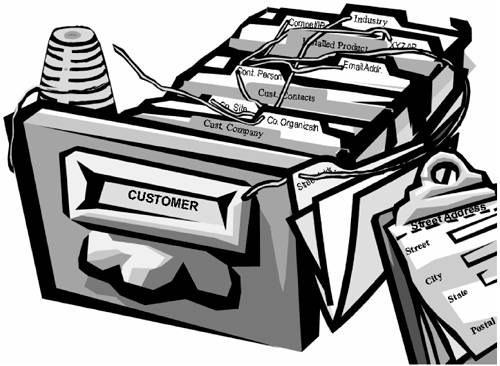
But that has changed. The database management systems most prevalent today (relational, object oriented) are designed to manage links between entities very efficiently. After these links are defined, the computer does the work of pulling everything together so it looks like one big form. The advantage is that we have also been able to eliminate all the repeated data required by the old method.
What Are Relationships?
Entity relationships have some specific technical characteristics that are important only to Information Technology. But let's get a quick overview. Relationships identify how two (and only two) entities interact with each other. From the business perspective, relationships are represented by a line connecting the two entities. In a physical database, a relationship is represented by including the key from one entity in the other entity. (Think of a U.S. Income Tax Form 1040. It has a line that represents all the information from Schedule A, Itemized Deductions.)
Relationships have names that describe the role that each entity plays with the other: A person owns an installed product; an installed product is owned by a person.
Relationships have cardinality that tells us the how many of one entity relates to how many of the other. Each end of the relationship has a lower limit and an upper limit.
Table D-13 shows the possible cardinalities for each end of the relationship. Zero as a possible lower limit means the relationship is optional. A relationship may have any of these four possible cardinalities on each end of the line.
| Lower Limit | Upper Limit | |||
| One | Many | |||
| Zero | zero or one | zero or many | ||
| One | one and only one | one or many | ||
There are more complex conventions available and used by many database designers, but these four are the basics. We will discuss more about what these mean in section D-5.
All entities within a project must be linked (not necessarily directly), or it makes no sense to have them as part of the project at all. Of course, we worry about only the relationships between the entities that are part of the project.
XYZ actually got a head start while defining the Valencia project entities and assigning attributes. In real life, the company started documenting relationships as new entities that were created to meet the normalization rules, but which needed to be linked to the original candidate entity. For clarity, we're taking these steps sequentially in practice.
Any entity whose key includes the key from another entity has a dependent relationship with that entity. XYZ started by quickly drawing the relationships between Contact Person and both E-mail Address and Competitive Product. It also drew links between Company Organization and Company Site, and Street Address and Company Site. It had already identified the minimum required relationships for six of the nine entities!
Let's look at the other three. Earlier, we discussed that XYZ identified a link between Industry and Company Organization. It also knew that Store described where an Installed Product was purchased, so that was another link. At this point, XYZ had created a preliminary entity relationship diagram that looks like the one in Figure D-5.
Figure D-5. Missing link?

But XYZ still had two separate groups with no link between them, and that's not allowed. There was a connection missing between the contact person and the address he gave. One question on the registration card asked whether the address was a home or business address. XYZ initially made this an attribute of Address. But sometimes, the address can be used for both home and business.
For business addresses, XYZ identified a link to Company Site (which we've already drawn). If it's a home address, the link is directly to Contact Person, representing XYZ's consumer customers. Business customers are linked to the Company Site where they work.
Finally, we must name the relationship and identify cardinalities. IT put all this together using a Computer Aided Software Engineering (CASE) tool (trust me, graphics software is NOT the way), and we got the entity relationship diagram for Valencia (and El Cid as well because Valencia was the first project) as shown in Figure D-6.
Figure D-6. The entity relationship diagram for Valencia

The relationships between XYZ's Valencia project entities can be “read” directly off this diagram. As an example, consider the relationship between Contact Person and Company Site:
A Contact Person is employed at zero or one Company Sites. (The Contact Person may be a consumer.)
Conversely, a Company Site employs zero to many Customer Contacts. (We may not know any of the contacts who work there, but we know the site exists.)
Next, the IT experts began constructing the physical computer “storage file” for this information.
The process takes some practice, but it's logical and consistent, and it follows step by step as long as you use a methodology. Because we normally work with only a small number of entities at a time, this really isn't all that difficult. And of course, lots of the relationships have already been identified by the time we've finished assigning attributes to entities.
D.4.6. Define Entities, Attributes, and Relationships
The business team has to worry about the business name and definition of each entity and attribute and relationship.
Entity
We saw how XYZ created the definitions for classes and subjects. Defining entities is just the same, so we won't go through that process again. Just remember that you can build off the subject definitions to help create the entity definitions. You don't have to start with a blank slate.
Attribute
When defining each of the attributes, XYZ had to do more than just give a business definition. IT takes over after the definitions are complete and identifies the size of the attribute, type of data being stored, and whether any special checks should be made on the value of each. Information Technology needs to be able to count on business participation to get this right. I have seen too many projects that had to be re-written because the IT team didn't know, for example, that the company's product models could have up to 18 characters, even though they are not often that long. Table D-14 holds the attribute definitions for the Installed Product entity.
There are some related concepts that the IT team uses that make the communication with the business team easier. One such tool is using a standard naming convention and standard abbreviations to generate consistent physical data names from the business-defined names. This topic is discussed in section D-7.
Relationship
Relationship definitions include the name, cardinality, optionality, and related entities, as we've just seen. Usually, these are defined using a data modeling tool and displayed as shown in the entity relationship diagram (refer to Figure D-6).