Chapter 12. Video, Audio, and Peripherals
Video makes a computer sparkle, audio makes it rock, and input devices and peripherals make it extremely accessible. This chapter describes the technologies and devices that transform the computer from a boring block of metal to a multimedia juggernaut. We could talk about video and audio for days, but lucky for you this chapter has a page limit! So we’ll stick to what you need to know for the exam.
This chapter is broken down into three sections. First, the video subsystem, which includes the video card and display. Second, the audio subsystem, which includes the sound card and speakers. And closing it out are input/output ports, devices, and peripherals. However, the bulk of the information in this chapter pertains to video, so let’s begin with that first.
The Video Subsystem
The computer can be broken down into several subsystems, the video subsystem being one of the most important. The video subsystem includes the video card (or integrated video), the card’s expansion bus, internal connections, external connections between the video card and the display, the display itself, and the video driver. This section details those portions of the video subsystem. Of course, it’s also vital to know how to install and configure video cards and how to troubleshoot any issues that might occur.
Video Cards
Today’s video cards are like little self-contained computers! They have a processor, known as a graphics processing unit (GPU), and a substantial amount of RAM. When deciding on a video card to use, there are several things to take into account including the expansion bus that the card will connect to, the card’s GPU speed and amount of memory, the connectors it offers, if there is an expansion slot available for it on the motherboard, whether the video card will fit in the case, and whether the case has adequate power and cooling capabilities for the card.
Expansion Busses: PCI, PCIe, AGP
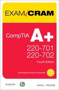
Before purchasing and installing a video card, make sure that the motherboard in the computer has a corresponding open expansion slot for the card. There are three expansion busses that can be used by video cards: Peripheral Component Interconnect (PCI), Accelerated Graphics Port (AGP), and PCI Express (PCIe), with PCIe being the most common expansion bus slot in today’s motherboards. Because PCIe and AGP have high data transfer rates, those expansion slots connect directly to the northbridge of a motherboard’s chipset. PCI however, has a lesser data transfer rate; therefore, PCI slots connect to the southbridge. Table 12.1 reviews the three expansion busses’ characteristics and differences. The color listed for each expansion bus is typical but not definite because some motherboard manufacturers select their own proprietary colors. Figure 12.1 shows a comparison of these expansion bus slots.
Table 12.1 Video Card Expansion Busses

Figure 12.1 PCIe, PCI, and AGP expansion bus slots
ExamAlert
Know the differences between PCI, AGP, and PCIe for the exam.
PCI Express won the battle against AGP as soon as the PCIe x16 card was released, which could initially transfer 4GB of data per second, double that of AGP. Since then, PCI Express has only gotten faster. PCI video cards are less common; although, an old PCI card works great in a pinch, and many motherboards still come with PCI slots. PCI also works well in some Multiple Monitor scenarios.
Installing a video card to a PCI or to an AGP slot is easy; just press the card straight down into the slot, and screw it into the chassis. However, PCI Express cards require a little bit more work, which is discussed later in this chapter. For more information on expansion busses, see Chapter 2, “Motherboards.”
Connector Types
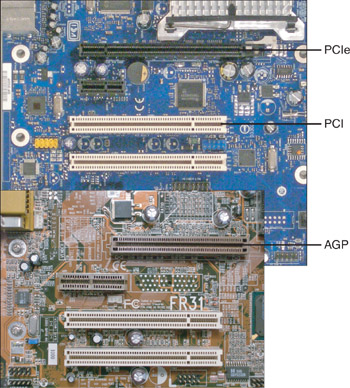
After a video card is decided on, that will probably dictate the connector used. Most of today’s PCIe video cards come with one or two DVI outputs, but there are several other connectors that you see in the field. Table 12.2 details these. Figure 12.2 shows a video card’s two DVI ports and the other ports described in Table 12.2.
Table 12.2 Video Card Connectors
Figure 12.2 DVI, VGA, HDMI, S-Video, and component video ports
ExamAlert
Be able to identify DVI, VGA, HDMI, S-Video, and component video ports for the exam.
Many DVI connectors on a video card look the same; however, it is the monitor’s cable and plug that define which type of DVI it can support. Figure 12.3 shows an illustration of the various DVI plugs, and their associated pins, that you might see on the end of a monitor cable.
Figure 12.3 Various DVI plug connector pins

A computer’s DVI connector is usually compatible with HDMI and VGA. Adapters and adapter cables are available if a user wants to connect a VGA monitor or HDMI television to the DVI port of a computer.
Video Card Chipset, GPU, and Memory
The video card, I selected for this book is the Gigabyte GeForce GTX 260. It was mentioned before that today’s video cards are like computers unto themselves. To a certain extent this is true. These cards have a chipset, similar to a motherboard’s chipset, but more simplified; it takes care of the connection between the graphics processing unit (GPU) and the RAM on the card. A video card name, such as GTX 260, is also the chipset name of the card. The GPU of a video card is measured quite like a CPU. For example, the GPU in the GTX 260 runs at 630MHz; this is known as its core clock. Likewise, a video card’s RAM is measured like a motherboard’s RAM. Many video cards already in the field use DDR and DDR2. Newer cards use DDR3, and some video cards are being developed during the writing of this book that use DDR4. Video card RAM is known as GDDR or Graphics Double Data Rate.
The GTX 260 has 896MB of DDR3 RAM, which runs at a whopping speed of 2,000MHz, and the memory bus is 448-bits wide. These numbers are usually ahead of motherboard RAM, especially in the bus width category. For example, motherboards are just now supporting DDR3 RAM (the motherboard used in this book supports only DDR2), and even with Dual Channel architecture, a motherboard’s maximum memory bus width is only 128-bit. Most new video cards (as of the writing of this book) are PCI Express x16, meaning they have a bus speed of 16 and can connect only to a PCIe x16 slot. Because today’s video cards have powerful GPUs, the GPU will have its own heat sink and fan, or the entire card will be enclosed and will have its own exhaust fan, thus cooling the GPU, chipset, and RAM.
Installing and Troubleshooting Video Cards
Video cards, like other adapter cards, are inserted into an expansion bus slot and then screwed into the chassis of the case to keep them in place. However, PCI Express cards require the installer to do a few more things. And keep in mind that newer PCIe cards are big. When deciding on a video card like this one, make sure it fits in the computer case first! The following steps describe how to install a PCIe video card:
Step 1. Check if the card is compatible: Verify that there is an open, compatible slot on the motherboard. Also, make sure that the card is compatible with the operating system. For more information on OS compatibility, see Chapter 7, “Installing and Upgrading Windows.”
Step 2. Ready the computer: Make sure that the computer is turned off and unplugged. Then implement ESD prevention measures (antistatic mat, antistatic wrist strap, and so on).
Step 3. Ready the video card: Remove the card from the package and place it on an antistatic bag until it is ready to be inserted. (Make sure the card is sealed when first opening it. In rare cases, used cards are repackaged and resold as new.)
Step 4. Document: If the computer had a video card already, document how and where it was connected. Otherwise, review documentation that came with the motherboard and video card, so a plan can be put into place as to where to install the card, and what cables need to be connected to the card (and how they should be routed through the case).
Step 5. Prepare the slot: Use a Phillips head screwdriver to remove the slot cover (or covers) where the card will be installed. Newer PCIe cards inhabit the space used by two slot covers. On most PCIe slots there will be a thumb lever. Open this gently. When the card is inserted, the lever locks the card into place. In some cases, this lever isn’t necessary.
Step 6. Install the card to the slot: Insert the card, using both thumbs, with equal pressure, straight down into the slot. Try not to wiggle the card in any direction. Press down until the card snaps into place and you can’t see any of the gold edge connectors. If it doesn’t seem to be going in, don’t force it. There might be something in the way; for example, one of the slot covers hasn’t been removed, or the thumb lever isn’t in the correct position.
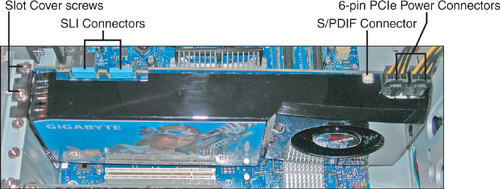
Step 7. Connect cables: PCIe cards need their own power connection (or two). These are 6-pin PCIe power connectors. Many cases come with PCIe power connectors, but if not, most PCIe video cards have a 6-pin PCIe to Molex adapter (or two). Next, make any SLI connections necessary, if you have two or three video cards (less common). Then, connect optional cables, for example, an S/PDIF header cable to the motherboard, and any other ancillary cables. When complete, it should look something like Figure 12.4.
Figure 12.4 An installed PCIe GTX 260 video card
Step 8. Test: Testing is simple; plug the monitor into the video card’s port, and boot the computer. If you don’t get anything on the display, it’s time to troubleshoot. Make sure that the monitor is connected securely to the correct port. Then (after shutting down the PC) make sure that the card is seated properly and that the power connections and any other connections are connected firmly. Listen for any beep codes that might be issued by the BIOS POST. Check if the computer is booting without video; this can be done by watching the LED lights on the front of the case and listening for the power supply fan and hard drive activity.
Step 9. Install the driver: When the system boots properly, install the driver from the manufacturer’s CD. If for some reason there weren’t a CD supplied with the device, or it is missing, go to the manufacturer’s website and download the latest version of the driver for the exact model of the video card.
Step 10. Test again: Now that the driver is installed, test again. Verify that the card is seen as the correct make and model in the Device Manager. Then make sure the display can output the desired resolution. Keep in mind that some video cards can output a higher resolution than a monitor can support. If the computer is used for graphics or gaming, open the appropriate application and verify that it works as expected. For example, check for fluidity, quick response, frame rate, and so on.
ExamAlert
Know how to install and test a video card for the exam.
When troubleshooting video issues, there are a number of things to check including
• Connections: If nothing is showing up on the display, first make sure that the monitor is plugged into the video card properly (and to the correct video port); then verify that the monitor is connected to the AC outlet and is powered on. If the image on the display is scrambled, check that it is connected to the correct port on the video card because some cards come with DVI and VGA ports.
• Resolution setting: In the case that the resolution was set too high, or to a resolution not supported by the monitor, boot into low resolution VGA mode or Safe Mode. This starts the computer with a resolution of 640x480. Then modify the resolution setting in the Display Properties window. More on resolution later in this chapter.
• Check the driver: Maybe the driver failed, or perhaps the wrong driver was installed during installation, or maybe an update is necessary. If there is nothing on the display, or if the image is distorted, or if the monitor only displays a lower resolution, boot into low res mode or Safe Mode, and update the driver from within the Device Manager.
• Check the version of DirectX: DirectX is a Windows technology that includes video, animation, and sound components. It helps a computer get more performance out of multimedia, games, and movies. The DirectX Diagnostic Tool (DxDiag) helps to troubleshoot DirectX-related issues. This tool gives information about the installed version of DirectX and whether it is operating correctly, among other things. The DirectX Diagnostic Tool can be started by opening the Run prompt and typing dxdiag.
• Check inside the computer: I usually leave this for last because it is time-consuming to open the system, unless I have a sneaky suspicion that one of the connections inside the computer is loose. Check if the card is seated properly. In areas where the temperature and humidity change quickly, the card could be unseated due to thermal expansion and contraction. (Some refer to this as chip creep or card creep!) Also, if the computer were moved recently, it could cause the card to come out of the slot slightly. Verify that the power connections and other cables are not loose. Check all other connections inside the PC in the case that it isn’t a video problem.
Once again, verify that it is actually a video problem. Don’t forget about the “big four.” When you can’t see anything on the display and you know the computer is receiving power, you can narrow it down to video, RAM, processor, and the motherboard. If the system appears to boot; if you can hear the hard drive accessing data, and can see hard drive activity from the LED light on the front of the case, it is most likely a video problem.
SLI and TV Tuner/Capture Cards
Gamers are always looking to push the envelope when it comes to video performance. It’s possible to take video to the next level by incorporating a technology known as Scan Line Interleave (SLI). This is when a computer has two (or more) identical video cards that work together for greater performance and higher resolution. The SLI compatible cards are bridged together to essentially work as one unit. The GTX 260 video card mentioned previously supports SLI, as shown in Figure 12.4. It is important to have a compatible motherboard and ample cooling when attempting this type of configuration. Currently this is done with two or more PCI Express video cards and is most commonly found in gaming rigs.
Home entertainment enthusiasts often have a computer hooked up to their home theater. If this is the case, they probably install a TV tuner card. These cards can accept the signal from a cable or satellite provider and then send it back out to the TV or other devices in the home theater. Most TV tuners also act as capture cards, meaning that they can capture the signal and record TV programs. The purpose of all this is to record shows onto the computer and basically use the computer as a digital video recorder (DVR), among other things. By using Window Media Center, which is built-in to Windows Vista and comes as a separate edition for Windows XP, users can control their TV experience. TV tuner cards are available with PCI Express, PCI, ExpressCard (for laptops), and USB interfaces.
Video Displays
Regardless of what type of video card (or cards) is in a computer, it all means nothing if the computer doesn’t have an output device. The most common video output device in a computer system is the liquid crystal display (LCD).
LCD
A liquid crystal display (LCD) is a flat panel display that consists of two sheets of polarizing material surrounding a layer of liquid crystal solution. Most of today’s LCD screens are thin-film transistor (TFT) active-matrix displays, meaning they have three transistors for each pixel, which are contained within a flexible material. The transistors store the electrical state of each pixel, while all the other pixels are updated. These transistors are located directly behind the liquid crystal material. In general, LCDs use low amounts of power, generate a small amount of heat, and cause little in the way of interference and emissions. Common LCD resolutions include WXGA, SXGA+, UXGA, WSXGA+, and WUXGA. Generally, an LCD will be designed for one resolution, known as the native resolution; it’s the resolution that the LCD works best at. If this is the case, any other resolution selected will be scaled and will usually appear stretched or compressed. If a user complains of these symptoms, check the LCDs documentation to find its native resolution, and switch to that resolution in the Display Properties window. More on video resolution later in this chapter.
Another measure of an LCD is contrast ratio. Contrast ratio is a comparison of the brightest and darkest colors (white and black) that can be generated on a display. It can be measured statically, or dynamically (known as DC). Generally, the higher the contrast ratio, the better. Dynamic will always be a higher number than static. For example, the monitor used for this book (Samsung 2343BWX) has a static contrast ratio of 1000:1 and a dynamic contrast ratio of 20000:1.
When it comes to cleaning displays, be careful; liquid can possibly get between the bezel and the screen; when it infiltrates the display assembly, bad things can happen! To avoid this, conservatively spray the cleaner on to a soft, clean, lint-free cloth first; then carefully clean the display with the cloth. Many manufacturers of displays recommend using isopropyl alcohol diluted with water; basically no more than 50 percent of the solution should be alcohol; the rest should be water. Isopropyl alcohol can be found in most supermarkets and drug stores; the higher the purity level the better, for example 90 percent purity is acceptable; it will say this directly on the bottle. Again, use the solution conservatively, apply it to the cloth first, and try not to get any on the plastic bezel, apply to the screen only. It usually isn’t necessary to clean the screen very often; once every 3 to 6 months is fine unless you work in a very dirty environment. Instead of cleaning the screen, you can also try removing the dust (which can affect visibility) with a soft lint-free cloth or a canister of compressed air. This might help as an added step before cleaning the screen to avoid streaking. There are also various spray cleaners available at electronics stores and online; some of them are simply expensive isopropyl alcohol/water solutions! But personally, for over a decade I have simply mixed my own isopropyl/water solution for use on LCDs, CRTs, laptop LCDs, handheld computers, PDAs, and cell phones, and have never had a problem.
CRT
A cathode ray tube (CRT) is an older type monitor that uses a vacuum tube display and utilizes three electron guns to display the colors red, green, and blue to a fluorescent screen. (Red, green, and blue are the three primary colors of the computer display world.) These colors are grouped into triads and are emitted by phosphors within the screen so that a user can see the image on the display. A triad consists of three “dots,” red, green, and blue. One way that CRTs are measured is in dot pitch, which is the distance between two like colors of adjacent triads. The lower the dot pitch, the better the CRT’s image quality because the triads are closer together. CRTs are higher in emissions and interference than LCDs.
Projectors
Video projectors can be plugged into a computer’s external video port to project the computer’s video display to a projection screen. An extremely bright bulb is necessary to project this image to the screen. The light output is measured in lumens. More lumens are necessary for locations with a higher amount of ambient light (existing light in the room). Projectors are used for presentations and for teaching and are common in conference rooms and training centers; however, some schools and companies opt to go for large flat screen TVs instead of using projectors, even though projectors can usually project a larger image. Projectors are available in CRT, LCD, and DLP versions. The CRT and LCD technologies work in a similar fashion to the monitor technologies of the same name, whereas DLP uses light valves with rotating color wheels. Common display resolutions for projectors include SVGA (800x600), XGA (1024x768), and high-definition resolutions such as 720p and 1080p; the price of the projector increasing with each type of resolution mentioned, and with other characteristics such as the brightness, contrast, and noise. A video projector can be used with a laptop, by utilizing the display toggle button, or can be used with a computer that has a video card with dual outputs.
Video Settings and Software
So, you’ve selected and installed a video card, and the monitor is connected to the computer. What next? Now it’s time to install drivers (if not done already during the installation process) and configure settings in Windows such as the color depth, resolution, refresh rate, plus features such as Multiple Monitor, and on-screen settings.
Drivers
Device drivers (otherwise known as software drivers) are programs that enable the operating system to communicate with the actual device. For example, a video driver enables the operating system to interact with the video card. The driver simplifies the amount of work that an application needs to do by acting as a go-between for the application and the device.
Video drivers (or the lack thereof) have been known to cause plenty a headache for technicians. However, if a couple of simple rules are adhered to, many of the plaguing video driver issues can be avoided:
• Use the manufacturer’s driver. When you install a video card, Windows attempts to use a Microsoft version of the driver. This is usually not the best option, especially for newer cards. Instead, use the driver that came on disc with the device, or better yet, access the manufacturer’s website to download the latest driver for the device. You can check the date of the driver on the website against the date listed in the Device Manager to see if you currently have the latest.
• Watch out for new operating systems. Newer operating systems don’t always have all the kinks worked out. Sometimes new hardware will not operate properly with a new operating system until updates have been released, or the first service pack has been issued for the operating system. Before installing a new operating system, verify that the device is listed as compatible. For example, when installing Windows Vista, visit the Windows Vista Compatibility Center. (For more information on compatibility, see Chapter 7.) Make sure to update the operating system after the installation is complete.
To work with video drivers in Windows, open the Device Manager and then expand the Display Adapters category. This shows the video card. Right-click the device and select Properties; then select the Driver tab. This shows a lot of information including the manufacturer of the driver. If it says Microsoft, consider downloading the latest driver from the manufacturer’s website. If it says NVIDIA, ATI, or something else, then you already have a manufacturer’s version of the driver, though it might not be the latest. From this window you can also see the date of the driver, update the driver to the latest version, roll back the driver if a new installation has failed, or uninstall the driver completely.
Sometimes, if a driver fails, the system will not display anything on the screen. If this happens, try pressing F8 during startup and boot into either Enable Low-Resolution Video (in Vista), Enable VGA Mode (in XP), or if those don’t work, attempt to boot into Safe Mode. These start the computer without the normal video driver and instead will use a basic VGA driver at 640x480 resolution. In some cases, the computer automatically asks you if you want to start in Safe Mode, recognizing that there is a video issue. Note that Enable Low-Resolution Video and Enable VGA Mode use a basic VGA driver, but all other drivers work normally. However, Safe Mode starts the system with a minimal set of drivers. If a driver does fail, Internet access might be required to download the latest driver. This is not available in Safe Mode, but it is available in either of the low resolution modes named previously.
Color Depth
Color depth (also known as bit depth or color quality) is a term used to describe the amount of bits that represent color. For example, 1-bit color is known as monochrome, those old screens with a black background and one color for the text, like in old Six Million Dollar Man episodes, or like Neo’s computer in The Matrix! But what is 1-bit? 1-bit in the binary numbering system means a binary number with one digit; this can be a zero or a one, for a total of two values: usually black and white. This is defined in scientific notation as 21, (2 to the 1st power equals 2). Another example would be 4-bit color, used by the ancient but awesome Commodore 64 computer. In a 4-bit color system you can have 16 colors total. In this case 24 = 16. Of course 16 colors aren’t nearly enough for today’s applications; 16-bit, 24-bit, and 32-bit are the most common color depths used by Windows.
Now that you know the basics, take a look at Table 12.3 that shows the different color depths used in Windows.
Table 12.3 List of Color Depths used in Windows

8-bit color is used in VGA mode, which is uncommon for normal use, but you might see it if you boot into Safe Mode, or other advanced modes that disable the normal video driver. 16-bit is usually enough for the average user who works with basic applications; however, many computers are configured by default to 24-bit or 32-bit (also known as 3 bytes and 4 bytes respectively). Most users will not have a need for 32-bit color depth; in fact, it uses up resources that might be better put to work elsewhere. If the user works only on basic applications, consider scaling them down to 24-bit or 16-bit to increase system performance. However, gamers, graphics artists, and other designers probably want 32-bit color depth. Some applications and games have the capability to work outside of Windows when it comes to color depth, and a user can select a different color depth for the application than what they use for Windows.
To modify color depth do the following:
• In Windows Vista: Right-click the desktop and select Personalize. Then click the Display Settings link. A drop-down menu for color depth is located near the bottom-right part of this window, as shown in Figure 12.5.
Figure 12.5 Color depth and resolution settings in Windows XP
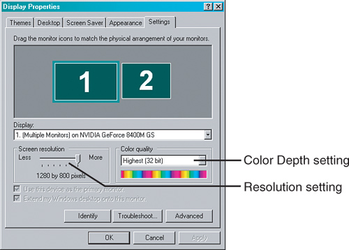
• In Windows XP: Right-click the desktop and select Properties. Then click the Setting tab within the Display Properties window. A drop-down menu for color depth is located near the bottom right of this window, as shown in Figure 12.5.
Resolution
Display resolution is described as the amount of pixels (picture elements) on a screen. It is measured horizontally by vertically (HxV). The more pixels that can be used on the screen, the bigger the desktop becomes, and a user can fit more windows on the display. The word resolution is somewhat of a misnomer and will also be referred to as pixel dimensions. Table 12.4 shows some of the typical resolutions used in Windows.
Table 12.4 List of Resolutions Used in Windows

Aspect ratio can be defined as an image’s width divided by its height; for example, XGA’s resolution is 1024x768. If we divide the width (1024) by the height (768), our result would be 1.333. You also hear this referred to as a four-to-three ratio (4:3). This means that for ever 4 pixels running horizontally, there are 3 pixels running vertically. Wider resolutions have a higher first number, for example 16:9. Most current laptops and desktop LCD screens use a widescreen format by default, either 16:9 or 16:10, though you can still purchase LCD monitors that are based off of the 4:3 ratio.
A common resolution for older desktop LCDs is XGA; however, even though they are older, you still see them in the field for a while. In fact I have one running in DualView mode off of my laptop right now. Today’s common resolutions for desktop LCDs and laptops are WXGA, SXGA+, UXGA, and WSXGA+. Display resolutions continue to get larger; there are a dozen or so higher standards that aren’t listed in Table 12.4. For example, the monitor used during the writing of this book has a maximum resolution of 2048x1152, which is known as QWXGA (Quad Wide eXtended Graphics Array). Keep in mind however, that the maximum resolution of a monitor can be achieved only if the video card can support it. Video cards’ maximum resolution is rated in two ways: maximum digital resolution and maximum VGA resolution. The VGA number is usually less than the digital number.
ExamAlert
Memorize the basic differences between XGA, WXGA, SXGA+, UXGA, WSXGA+, and WUXGA for the exam.
To modify screen resolution in Windows do the following:
• In Windows Vista: Right-click the desktop and select Personalize. Then click the Display Settings link. Toward the bottom-left part of the window is a box called Resolution, which has a slider that enables you to configure the pixel dimensions. Drag the slider to the appropriate resolution. This slider is indicated in Figure 12.5.
• In Windows XP: Right-click the desktop and select Properties. Then click the Setting tab within the Display Properties window. Toward the bottom-left part of the window is a box called Screen resolution, which has a slider that enables you to configure the pixel dimensions. Drag the slider to the appropriate resolution. This slider is indicated in Figure 12.5.
Sometimes a user might set the resolution too high, resulting in a scrambled or distorted display. This can happen when video cards support higher resolution modes than the monitor does. If this happens, reboot the computer into either Enable Low Resolution Video (Enable VGA Mode in XP) or Safe Mode and adjust the resolution setting to a level that the monitor can support.
A video card’s amount of memory dictates the highest resolution and color depth settings. You can multiply the resolution by the color depth to find out how much memory will be needed. For example, if a user wanted to run at 1920x1080 resolution at 32-bit color (4 bytes of color), the equation would be 1920 × 1080 × 4, which would equal approximately 8MB, easily covered by most video cards. But keep in mind that this is the bare minimum needed to display Windows and that more will be necessary for advanced GUIs such as Windows Aero. Much more video memory is necessary to run games and graphics programs. Some desktop computers and laptops have integrated video, which use shared video memory. This means that instead of the video device having its own memory, it shares the motherboard’s RAM. Motherboard RAM will usually be slower than a video card’s memory, and there will probably be less available. Due to this, a PCI Express video card is recommended over integrated video for computers that run resource-intensive applications and games.
Refresh Rate
Refresh rate is generally known as the amount of times a display is “painted” per second. It is more specifically known as vertical refresh rate. Refresh rate works differently in LCDs and CRTs.
On a CRT, the display is painted in horizontal lines one at a time from top to bottom, at high speed. This is done by an electron beam. When the entire display has been painted, it is considered one refresh. By default on many systems, this is set to occur 60 times per second, or 60 Hz. However, to reduce eye strain when working with CRTs, it is possible to increase this number to a higher amount, for example 72Hz or 85Hz, which reduces flicker. The faster the screen is painted, the less a user’s eyes have to work to register what they see. Keep in mind that the video card must support a higher refresh rate to match the monitor.
On an LCD, refresh rate works differently because LCDs use a completely different technology to paint the screen. Instead of painting the screen at x times per second, the liquid crystal material is illuminated. However, you can still modify the Windows refresh rate, which effectively configures how many times per second a new image is received from the video card. This is usually set to 60Hz and is not configurable on most LCDs. Flicker is not as much of an issue on LCDs because the backlight (lamp) is set to it’s own rate, usually at 200Hz. Because refresh rate is not configurable on most LCDs, you might not see this measurement in an LCDs specifications (aside from the newer 120Hz models).
To modify the Windows refresh rate for CRTs or LCDs:
• In Windows Vista: Right-click the desktop and select Personalize. Then click the Display Settings link. Click the Advanced Settings button and click the Monitor tab. Select the Screen refresh rate from the drop-down menu.
• In Windows XP: Right-click the desktop and select Properties. Then click the Setting tab within the Display Properties window. Click the Advanced button and then click the Monitor tab. Select the Screen refresh rate from the drop-down menu.
Don’t confuse the refresh rate with frames per second (frames/s or fps). Although the two are directly related, they are not the same thing. For example, if playing a video game that is set to run at 90 frames/s, the game attempts to send those frames of video data from the video card to the monitor. However, the monitor might be limited to a 60Hz refresh rate. If this is the case, the video card attempts to display the additional frames within the given refresh rate, causing a sort of blur, which might or might not be acceptable to the user. To many users in the gaming community, the higher the frames/s, the better. But to actually attain a higher frame rate, a higher refresh rate will also be necessary. With a CRT monitor this was historically 85Hz or higher; with an LCD monitor, this higher refresh rate wasn’t available until recently with newer 120Hz technologies. The LCD used for the writing of this book runs at a native refresh rate of 60Hz. An example of an LCD that runs at 120Hz is the Samsung 2233RZ.
OSD and Degaussing
The on-screen display (OSD) can help configure picture quality. It can aid in fixing problems of all types including distortion, picture size, centering, and contrast and brightness. The OSD is superimposed on top of the monitor’s display and can usually be accessed by pressing a Menu button or other like button on the monitor either below the display or on one of the sides of the monitor. From there, arrow buttons enable the user to make modifications to the settings. Typical settings for LCDs and CRTs include picture size, picture centering, contrast, and brightness. Keep in mind that laptop displays usually have only a brightness setting.
CRT displays also offer the ability to degauss the screen. Degaussing is the process of decreasing an unwanted magnetic field in the CRT. The CRT has a metal plate near the front of the monitor that picks up magnetic fields, which over time produce discoloration or other undesired effects on the screen. To degauss the screen (and remove the unwanted effects), there is usually a degauss option within the OSD menu, or there will be a degauss button directly on the monitor. If pressed, the whole screen distorts and shakes for a moment, and then should return to normal, without the discoloration or other undesired effects. Be careful with the degauss feature, it is not meant to be used often.
Multiple Monitor
Multiple Monitor (also referred to as DualView) is a Windows feature that extends the desktop across to multiple displays; it enables you to spread applications over two or more monitors that effectively work together as one. This works well for applications that are very wide, or if a user needs to see multiple windows at the same time. The additional screens used in Multiple Monitor do not have a taskbar; they just have the wallpaper or background that was selected. It is possible to select any of the monitors connected to the computer as the primary monitor, meaning the one with the Start button, taskbar, and so on. To enable Multiple Monitor, follow these steps:
Step 1. Connect an additional monitor to one of the extra video ports on the computer. Newer video cards have a DVI port. But you can still connect older SVGA monitors; just use a DVI to VGA adapter. (These are included with many of today’s video cards.)
Step 2. Turn on the secondary monitor.
Step 3. Open the Display Settings window in Vista or the Display Properties window in XP.
• In Windows Vista: Right-click the desktop and select Personalize. Then select Display Settings. This opens the Display Settings window.
• In Windows XP: Right-click the desktop and select Properties. This opens the Display Properties window. Select the Settings tab.
Step 4. Click on the Display drop down menu. Multiple Monitors should be listed. If it is not listed, the video card (or cards) might not support Multiple Monitor, or a driver upgrade might be necessary. Check your video card documentation to find out if it supports Multiple Monitor.
Step 5. Select the monitor with the number 2, either in the display or in the drop-down menu, and check mark Extend My Windows Desktop on to This Monitor. By using the Identify button and dragging the monitors around in the display window, you can arrange your monitors so that they match their physical position.
Step 6. Click Apply. The mouse should extend all the way across both monitors now. Verify that the secondary monitor is functional by dragging a window to that display. If all is good, click OK to close the Display Settings/Display Properties window.
Step 7. Repeat steps 1–6 for additional monitors beyond the second. Up to ten can be used with the Multiple Monitor feature.
It is possible to use multiple video cards, but keep in mind that the Windows Vista version of Multiple Monitor works only with identical video cards and drivers. Windows XP might work with different cards/drivers, but it is not recommended. Some applications (for example video players) might not work perfectly on a secondary screen. This depends on the type of video played, the application, and the type of monitor used.
ExamAlert
Know how to set up Multiple Monitor in Windows Vista/XP.
Note
For laptops, the Multiple Monitor feature is known as DualView and can have only a maximum of two monitors. Also, the laptop display is always the primary monitor in DualView setups. For more information on DualView and laptops, see Chapter 11, “Laptops.”
For more information on Multiple Monitor/DualView, see the following link: http://www.microsoft.com/windowsxp/using/setup/hwandprograms/monitors.mspx.
Cram Quiz
Answer these questions. The answers follow the last question. If you cannot answer these questions correctly, consider reading this section again until you can.
1. Which expansion bus slot is typically white in color?
![]() A. PCIe
A. PCIe
![]() B. AGP
B. AGP
![]() C. PCI
C. PCI
![]() D. LCD
D. LCD
2. Which of the following supports digital only connections?
![]() A. DVI-A
A. DVI-A
![]() B. DVI-D
B. DVI-D
![]() C. DVI-I
C. DVI-I
![]() D. VGA
D. VGA
3. When installing a video card, what should you do before inserting the card into the slot?
![]() A. Connect cables
A. Connect cables
![]() B. Install drivers
B. Install drivers
![]() C. Test
C. Test
![]() D. Prepare the slot
D. Prepare the slot
4. A user set the resolution in Windows too high resulting in a scrambled distorted display. What should you do?
![]() A. Upgrade the video driver.
A. Upgrade the video driver.
![]() B. Boot into low resolution mode.
B. Boot into low resolution mode.
![]() C. Boot into the recovery console.
C. Boot into the recovery console.
![]() D. Check the video connections.
D. Check the video connections.
5. Which of the following uses a TFT active-matrix display? (Select all that apply.)
![]() A. LCD
A. LCD
![]() B. CRT
B. CRT
![]() C. Projector
C. Projector
![]() D. Laptop
D. Laptop
6. Where is the best place to get the latest driver for a video card?
![]() A. Microsoft
A. Microsoft
![]() B. CD-ROM
B. CD-ROM
![]() C. A friend
C. A friend
![]() D. Manufacturer’s website
D. Manufacturer’s website
7. How many colors are there if the color depth in Windows is set to 24-bit?
![]() A. 16
A. 16
![]() B. 65,536
B. 65,536
![]() C. 16,777,216
C. 16,777,216
![]() D. 24
D. 24
8. A computer is set to 1280x1024 resolution. Which standard is it using?
![]() A. XGA
A. XGA
![]() B. SXGA
B. SXGA
![]() C. UXGA
C. UXGA
![]() D. WXGA
D. WXGA
9. What resolution does Windows use when started in Safe Mode?
![]() A. 800x600
A. 800x600
![]() B. 1024x768
B. 1024x768
![]() C. 640x480
C. 640x480
![]() D. 1280x800
D. 1280x800
10. What is a common refresh rate for an LCD?
![]() A. 30Hz
A. 30Hz
![]() B. 60Hz
B. 60Hz
![]() C. 200Hz
C. 200Hz
![]() D. 60MHz
D. 60MHz
11. What is the maximum amount of monitors a user can have in a Multiple Monitor environment?
![]() A. 10
A. 10
![]() B. 2
B. 2
![]() C. 4
C. 4
![]() D. 1
D. 1
Cram Quiz Answers
1. C. Peripheral Component Interconnect (PCI) slots are usually white in color. PCIe are often black or blue, AGP slots are often brown, and LCD is a type of monitor.
2. B. DVI-D supports digital-only connections, which are common on newer LCDs. DVI-A supports analog-only. DVI-I supports both digital and analog, and VGA is an analog connection.
3. D. Before inserting the card into the slot, prepare the slot by manipulating any locking mechanism and removing the appropriate slot cover(s).
4. B. Boot into a low-resolution mode. In Windows Vista this is called Enable Low Resolution Mode, and in XP it is called Enable VGA Mode. Safe Mode is another valid option, but keep in mind that Safe Mode loads Windows with a minimal set of drivers, and you can’t access the Internet if necessary.
5. A and D. Liquid Crystal Displays normally use the TFT active-matrix technology. Laptops have LCDs so they use the same technology.
6. D. The manufacturer’s website is the best place to get the latest driver. The CD-ROM supplied with the card is usually satisfactory, but it will not be the latest driver.
7. C. 24-bit color is equal to 16,777,216 colors in total, otherwise known as 224 power. Sixteen colors would be 4-bit, 65,536 colors would be 8-bit, and there is no setting that allows for 24 colors.
8. B. Super eXtended Graphics Array (SXGA) resolution is 1280x1024.
9. C. Safe Mode boots the computer with a minimal set of drivers including the video driver. Due to this, the resolution is set to 640x480 VGA mode.
10. B. A typical refresh rate for LCDs is 60Hz.
11. A. The Multiple Monitor feature in Windows Vista/XP supports up to 10 monitors. A laptop supports a lesser version of Multiple Monitor known as DualView, which supports a maximum of 2 monitors.
The Audio Subsystem
In some environments, sound is not required; but more often than not, it is either desired or is mandatory. So although troubleshooting sound is not as common as troubleshooting video (in most environments), it is still something that a technician will do fairly commonly in the field.
The audio subsystem consists of the sound card, the expansion bus used, audio ports, connectivity in the form of internal and external audio cables, speakers, sound card drivers, and any additional third-party audio software. The sound card is the basis for audio, so let’s begin by discussing that device now.
Sound cards
The sound card is responsible for generating sound from the data sent to it by either the CD-ROM drive or the operating system. Sound cards can be integrated into the motherboard, installed to PCI and PCIe slots, and can be connected to USB and IEEE 1394 ports. However, the typical soundcard is installed to a slot on the motherboard.
In the computer built for this book, I decided to go with the Creative Labs Sound Blaster X-Fi Titanium. It’s a PCIe x1 card, which means that it can fit within a x1, x4, or x16 slot. It has most of the ports a user would need for outputting and inputting sound. Figure 12.6 shows the ports on the back of this card and the integrated audio ports on the back of the motherboard used in Chapter 2.
Figure 12.6 A typical sound card’s ports and integrated audio ports on a motherboard

Most sound cards are color-coded. This color scheme is defined by the PC System Design Guide, version PC 99 (which was finalized as version PC 2001). It specifies the following colors for the TRS 1/8 inch mini-jacks like the ones shown in Figure 12.6:
• Light blue: Line input. Sometimes this seconds as a microphone input.
• Pink: Microphone input.
• Lime green: Main output for stereo speakers or headphones. Can also act as a line out.
• Black: Output for surround sound speakers (rear speakers).
• Gray/Brown: Output for additional two speakers in a 7.1 system (middle surround speakers).
• Orange: Output for center speaker and subwoofer.
On the sound card in Figure 12.6, note an optical input and output. This is known as an Sony/Phillips Digital Interconnect Format (S/PDIF) port. This particular version of S/PDIF is called TOSLINK. It delivers high-quality digital sound over fiber optic cable. It is also known as a digital optical port. It is considered by some to be sonically superior to the analog 1/8-inch mini-jacks described previously. The S/PDIF output can be used to connect to a home theater system or other receiver; this enables the user to play CDs, MP3s, and so on, on the system of their choice. The input can connect recording equipment, game consoles and so on, enabling a user to bring high-quality audio into the computer to be manipulated as the user sees fit. Cables connecting TOSLINK ports can be a maximum of 10 meters, but are normally found in 5 meter lengths.
Installing a Sound Card and Speakers
Installing a sound card is much like installing any other card. First be sure that the card is compatible with the installed operating system. Then employ ESD prevention measures. The card should be inserted into a PCI or PCIe slot by pressing straight down with both thumbs, making sure not to wiggle the card in any direction; this way the contacts will not get damaged. Make sure it is fully inserted; you shouldn’t see any of the gold-colored edge contacts. Then screw the card in where the slot cover used to be within the case.
However, we aren’t finished. Now we need to connect any front panel case connections that the card might support, hook up the CD-ROM drive if necessary, connect the speakers, and finally install the driver for the card:
• Make front panel connections: One common type of front panel connection is known as Intel High Definition Audio. This uses a 10-pin cable that goes from a compatible sound card (or motherboard if sound is integrated) to the front of an AC’97 compatible case. It is keyed at pin 8 so that the cable cannot be connected upside down. This port enables a user to connect headphones and a microphone to the front of the case instead of having to connect them to the sound card on the back of the computer. Creative Labs and other manufacturers also offer advanced devices that can be installed to a 5.25-inch bay so that the user can have greater access to connections, volume, and so on.
• Connect the CD-ROM drive: Newer computers running Windows XP or Vista do not need a CD audio cable. Music CDs are played directly through the data connection, be it IDE or SATA. However, to play audio CDs on an older computer with an older operating system, you need to connect a CD audio cable from the sound card to the CD-ROM drive. The two options are to connect a 4-pin analog cable or a 2-pin digital cable if your CD-ROM drive supports it. These two ports are usually located on the edge of the sound card and can be found on the back of the CD-ROM drive. Without this cable, audio CDs cannot be heard from the computer’s speakers on older systems. Many newer sound cards do not even offer a CD audio cable port, and newer SATA CD-ROM drives and DVD/CD combo drives will not have the CD audio cable port.
• Connect the speakers: Back in the day a pair of speakers would be connected to the sound card, and you were done. But now, you might be using a 5.1 or 7.1 system, and if so, you need to color coordinate! 5.1 surround sound means that the system is using five regular speakers (left, right, center, back left, and back right) and one speaker for low frequencies, which is usually a subwoofer. 7.1 builds upon this by adding two additional surround speakers. Normally, the lime green output is for the first two speakers (or headphones), which gives standard stereo 2.1 output (two speakers + sub). The black output is for two rear speakers, and the orange output is for the center channel and the subwoofer; an AC outlet will be necessary to power the subwoofer. A grey, brown, or other dark port is used for two additional speakers (middle surround) in a 7.1 system. Another option is to use the digital fiber optical output or digital coaxial output. There are a lot of options, so read the manual on the sound card and the speakers when trying to hook everything together, and pay attention to the little icons that are engraved into the back of the sound card next to the ports.
• Install the driver and software: Installing a sound card driver is usually done from the Installation CD that accompanies the sound card. It’s also wise to check the manufacturer’s website for any critical updates to the driver files. The CD usually comes with additional software to take control of the sound card. Keep in mind that this software might conflict with other audio software, or media player software that was already installed on a PC. Consider using one or the other for things such as volume, equalization, and sound effects. Disable or uninstall any unused audio applications or media players to avoid conflicts.
ExamAlert
Know how to install sound cards, connect speakers, and connect other internal audio connections for the exam.
Audio Quality
Audio quality is measured in several ways, but it all starts with the sampling rate and the amount of bits per sample (known as bit depth). Standard audio CDs have a sampling rate of 44kHz, sampling 16 bits at a time (known as 16-bit) per channel, using two channels (known as stereo or 2.1). This is referred to collectively as 16-bit/44kHz and is considered CD-quality. For stereo output of music this has been the standard ever since CDs were first developed in the 1980s. Songs are recorded to the CD in an uncompressed format known as a .WAV file. Another measurement you might see or hear of is the total data rate (or bit rate). This is the amount of bits that the CD plays per second and is calculated as sampling rate × bits × channels, or 44,100 × 16 × 2 = 1,411,200 bits, or 1411kbps. A standard audio CD is designed to play a maximum of 74 minutes of music at 1411kbps. To find the total capacity of an audio CD, we would multiply 1,411,200 bits × 74 (minutes) × 60 (seconds). This would come to a total of 783 million bytes, essentially a 750MB CD.
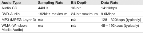
There are technologies that use higher data rates, and technologies that use lower data rates. For example, DVD-Audio (DVD-A) can be recorded at a maximum of 24-bit/192kHz in stereo. Given this fact, many sound cards (including the one installed during this chapter) can output at 24-bit/192kHz. And DVD-Audio might go beyond just two speakers; it might be designed for 5.1 surround sound; however, it would be at a lesser sampling rate. On the other end of the spectrum, MP3s, which are compressed versions of audio files, generally range between 128kbps and 320kbps. Compare this to CD quality that is 1411kbps. However, MP3s and other compressed audio files are done in a smart way to retain CD-quality sound. Table 12.5 compares CDs, DVDs, and a couple types of compressed music files.
Table 12.5 Comparison of Audio Types
ExamAlert
Know the basic differences between Audio CDs, DVD-Audio, and compressed music files for the exam.
Media players like Windows Media Player (which is built in to Windows) and Winamp can play audio CDs, DVD-Audio, and compressed files such as .mp3 and .wma. Certain versions of these programs can also “rip” CDs, taking the song from the CD, and creating a compressed .wma or .mp3 from it (if the CD is not encrypted). These compressed files can be anywhere from one-tenth to one-fourth the size of the original .WAV file on CD. They can then be transferred to just about any type of device including portable music players, USB flash drives, SD cards, and so on.
Cram Quiz
Answer these questions. The answers follow the last question. If you cannot answer these questions correctly, consider reading this section again until you can.
1. What types of cables are used to connect speakers to a sound card? (Select all that apply.)
![]() A. 1/8-inch mini-jacks
A. 1/8-inch mini-jacks
![]() B. DVI
B. DVI
![]() C. S/PDIF
C. S/PDIF
![]() D. RCA
D. RCA
2. Which of the following are commonly used expansion busses for sound cards? (Select all that apply.)
![]() A. AGP
A. AGP
![]() B. PCI
B. PCI
![]() C. PCIe
C. PCIe
![]() D. AMR
D. AMR
3. What standard is followed by most sound card manufacturers for the colors of the 1/8 mini-jacks?
![]() A. PCI
A. PCI
![]() B. PC 99
B. PC 99
![]() C. PC 100
C. PC 100
![]() D. PCIe
D. PCIe
4. What is the total data rate of an audio CD?
![]() A. 320kbps
A. 320kbps
![]() B. 160kbps
B. 160kbps
![]() C. 1411kbps
C. 1411kbps
![]() D. 9.6Mbps
D. 9.6Mbps
Cram Quiz Answers
1. A and C. The colored connectors on the back of the sound card are known as TRS 1/8-inch mini-jacks. S/PDIF is the optical output (and possibly input) found on the back of the sound card. DVI is a video port, and RCA is another port that can be used for video and audio but won’t be found on the back of a sound card; however, RCA might be found on I/O drives that are loaded into the front of a computer in a 5.25-inch bay, enabling for greater connectivity on the computer’s front panel.
2. B and C. PCI Express (x1) and PCI are common expansion busses for sound cards. AGP is for video-only, and AMR, although it used to be utilized for combination sound/modem cards, it is rarely seen today.
3. B. PC 99 specifies the color scheme used by all kinds of equipment including a sound card’s 1/8 mini-jacks.
4. C. 1411kbps is the total data rate (or bit rate) of an audio CD. 320 kbps is the maximum data rate for MP3, 160kbps is a common data rate for WMA files, and 9.6Mbps is the total data rate of DVD-Audio.
Input/Output, Input Devices, and Peripherals
To take advantage of a computer, the appropriate input/output devices and peripherals must be connected to the proper input/output (I/O) ports. Keyboards, mice, and multimedia devices can be connected to a variety of ports, most commonly, USB. This section briefly describes those devices and the ports they connect to.
I/O Ports
I/O ports enable a user to input information by way of keyboard, mouse, and microphone; plus they enable the output of information to printers, monitors, USB devices, and so on. The CompTIA A+ exams require a person to describe USB, IEEE 1394 (FireWire), serial, and parallel ports. The most common of these by far is USB.
USB
Universal Serial Bus (USB) ports are used by many devices including keyboards, mice, printers, cameras, and much more. The USB port enables data transfer between the device and the computer and usually powers the device as well. The speed of a USB device’s data transfer depends on the version of the USB port, as shown in Table 12.6.
Table 12.6 Comparison of USB Versions

The most common of these is USB 2.0, although USB 1.1 ports are also common in older computers. USB 1.0 is deprecated, and although USB 3.0 has been released, products complying to the standard are not expected until late 2009 or 2010.
ExamAlert
Memorize the specifications for USB versions 1.1 and 2.0 for the exam.
A computer can have a maximum of 127 USB devices. However, most computers have only 4 or 6 USB ports. To add devices beyond this, a USB hub can be used, but no more than five hubs can be in a series of USB devices. All cables connecting USB devices must comply with their standard’s maximum length. USB version 1.1 cables are limited to 3 meters in length (a little less than 10 feet), and USB version 2.0 cables can be a maximum length of 5 meters (a little more than 16 feet). The standard USB cable has four pins: a +5 V pin for power, positive and negative data pins, and a ground pin. Most USB connections are half-duplex, meaning that the device can send or receive data, but not both simultaneously.
There are various plugs used for the different types of USB connections. The most common are Type A and Type B, which are 4-pin connectors, but there are also mini- and micro-connectors, which are 5-pin. Type A connectors are the type you see on the back of a computer or on the side of a laptop. Figure 12.7 displays an illustration of these connectors.
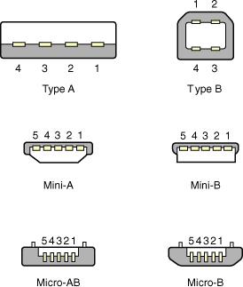
Type A and Type B connectors are commonly used for printers and other larger devices. Mini- and micro-connectors are often used for handheld computers, PDAs, digital cameras, portable music players, and cell phones. However, some companies create proprietary cables and connectors for their devices based off of the USB specifications. These devices will not connect properly to Type A, Type B, mini- or micro-connectors.
By default a USB device is designed to be a host or a slave. The host is in charge of initiating data transfers. However, USB version 2.0 introduced On-The-Go (OTG), which enables a device to act as both host and slave. This is more common in handheld computers, PDAs, and cell phones, devices that connect with either mini- or micro-plugs.
USB devices connect to what is known as a root hub, regardless of whether they are USB version 1.1 or 2.0 devices. The USB devices, root hub, and host controllers can be viewed from within Windows in a couple of ways:
• Device Manager: Within Device Manager, click Universal Serial Bus Controllers to expand it. The root hub and controllers are listed within. Individual devices will be listed under such categories as Human Interface Devices.
• System Information: Open System Information by opening the Run prompt and typing msinfo32. Expand Components, and select USB.
• Third-party tools: Third-party tools such as UVCView can analyze your USB devices, ports, root hub, and controllers.
When troubleshooting USB devices keep a few thing in mind:
• Verify that USB is enabled in the BIOS: It is possible to enable/disable USB within the BIOS. Keep this in mind when troubleshooting USB devices that are not functioning whatsoever. The user might have inadvertently set this to disabled, or perhaps the computer was shipped in that state.
• Make sure the computer is running USB 2.0: If the computer is USB 2.0-compliant from a hardware standpoint, make sure it is running USB 2.0 on the software side. Some versions of Windows support only USB 1.1 by default but with an update can support USB 2.0. This makes a huge difference in the speed of data transfer. Sometimes Windows informs the user that an update to USB 2.0 is available and that the USB devices work faster if this update is completed.
• Verify connectivity: Make sure the device is plugged in and that it is using the correct cable. Some incompatible USB plugs might look similar to the correct plug and might even connect to a device.
One of the problems with USB is how it suffers from latency. Due to this fact, users who work with audio and video prefer a zero-latency connection such as IEEE 1394.
IEEE 1394
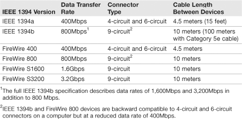
The Institute of Electrical and Electronics Engineers (IEEE) is a nonprofit organization that creates standards regarding cables and connectors and other technology related to electricity. One common standard is IEEE 1394, also known by the brand name versions FireWire, i.Link, and Lynx. It is a port used for devices that demand the low-latency transfer of data in real time, usually music or video. Up to 63 devices can be powered by a computer, with no more than 16 devices per chain. Table 12.7 describes some of the IEEE 1394/FireWire versions.
Table 12.7 Comparison of IEEE 1394/FireWire Versions
ExamAlert
Memorize the specifications for IEEE 1394a and b, and FireWire 400 and 800 for the exam.
Serial Versus Parallel
USB and FireWire are both serial busses that were designed to be faster than the original serial bus, which for the most part utilizes the RS-232 standard for the transmission of data. The original 9-pin serial ports are known as DE-9 connectors. (Some people incorrectly refer to them as DB-9 connectors.) These are used with external modems and to communicate directly with networking equipment such as routers. It is rare to see these integrated into today’s motherboards anymore, but in networking environments, you might see them on older computers/laptops or perhaps added on as a PCI card so that a network engineer can communicate with various networking equipment. These ports send data serially, meaning one bit at a time. Generally Windows limits these ports to 115.2Kbps (115,200bps). Dial-up connections through an external modem are limited to 56Kbps.
Parallel connections can deliver more than one bit simultaneously, usually in multiples of eight. This way, one, two, or more bytes of information can be sent at one time. An example of a parallel port is the deprecated 25-pin DB-25 port, also known as a printer port, although other devices like scanners and older SCSI devices could connect to that port. Later, additional types of parallel connectors were developed for the SCSI standard. See Chapter 6, “Storage Devices,” for more information on SCSI.
PS/2
The PS/2 connector is used for connecting keyboards and mice to a desktop computer or laptop. The PS/2 port was originally introduced in the late ‘80s as part of IBM’s Personal System/2 computer. Keyboards and mice connect via a 6-pin Mini-DIN connector. In the PC 99 color scheme, PS/2 keyboard ports are purple, and PS/2 mouse ports are green. Most manufacturers comply with this standard, although you may see a few (such as Compaq) that have historically used their own color schemes.
Though PS/2 had almost a 20-year run, these connectors are extremely rare on new computers; they were the standard until USB became popular. PS/2 keyboards are automatically configured as Interrupt ReQuest (IRQ) 1, and PS/2 mice are configured as IRQ 12 on a Windows system.
Input Devices and Peripherals
Let’s briefly discuss the types of devices used to input information and the various peripherals a technician might see in the field.
The usual suspects include the keyboard, for typing information in Windows, and the mouse, for manipulating the GUI. These two are known as human interface devices (HID). Some other devices that you might not have seen yet include KVM switches, touch screens, digital cameras, web cameras, microphones, biometric devices, bar code readers, and MIDI devices. Table 12.8 describes these devices.
Table 12.8 Description of Various Input Devices and Peripherals
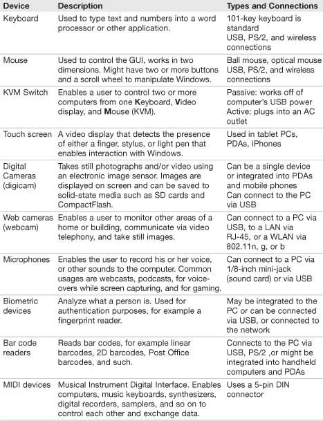
Troubleshooting any of the devices in Table 12.8 is usually quite easy. Make sure that the device is connected properly to the computer (or has a working wireless connection), and verify within the Device Manager that the latest drivers are installed for the device. Then, find out if any additional software is necessary for the device to function. Portions of the software might have to be installed to the device and to Windows.
Cram Quiz
Answer these questions. The answers follow the last question. If you cannot answer these questions correctly, consider reading this section again until you can.
1. What is the data transfer rate (speed) of USB 2.0?
![]() A. 12Mbps
A. 12Mbps
![]() B. 400Mbps
B. 400Mbps
![]() C. 480Mbps
C. 480Mbps
![]() D. 5Gbps
D. 5Gbps
2. What is the maximum amount of USB devices a computer can support?
![]() A. 4
A. 4
![]() B. 63
B. 63
![]() C. 127
C. 127
![]() D. 255
D. 255
3. Which type of USB connector is normally found on a desktop PC or laptop?
![]() A. Type A
A. Type A
![]() B. Type B
B. Type B
![]() C. Type C
C. Type C
![]() D. Type D
D. Type D
4. A user calls you with a complaint that none of his USB devices are working. What is the most probably cause?
![]() A. The USB 2.0 controller has failed.
A. The USB 2.0 controller has failed.
![]() B. The root hub is not configured.
B. The root hub is not configured.
![]() C. USB is disabled in the BIOS.
C. USB is disabled in the BIOS.
![]() D. USB is disabled in Windows.
D. USB is disabled in Windows.
5. What is the maximum data transfer rate of IEEE 1394a?
![]() A. 400Mbps
A. 400Mbps
![]() B. 800Mbps
B. 800Mbps
![]() C. 1,600Mbps
C. 1,600Mbps
![]() D. 3,200Mbps
D. 3,200Mbps
Cram Quiz Answers
1. C. USB 2.0 has a maximum data transfer rate of 480Mbps. 12Mbps is the data rate for USB version 1.1; 400Mbps is the data rate of IEEE 1394a (FireWire 400). And 5 Gbps is the data rate for the new USB 3.0.
2. C. USB can support up to 127 devices on one computer. However USB hubs will be necessary to go beyond the amount of USB ports (usually 4 or 6) commonly found on a system. FireWire supports up to 63 devices.
3. A. Type A connectors are almost always included on desktop PCs and laptops.
4. C. If none of the USB devices are working, chances are that USB has been disabled in the BIOS. This might be company policy so that users can’t access USB drives or boot the computer to one. If the USB 2.0 controller fails, the USB 1.1 controller should kick in (at a slower data transfer rate, of course). The USB root hub requires no configuring; it is auto-configured by Windows. Although it might be possible to disable one USB device at a time in Windows, it will be uncommon; disabling all the devices in Windows is rare.
5. A. IEEE 1394a specifies a maximum data transfer rate of 400Mbps. IEEE 1394b specifies 800Mbps, 1,600Mbps, and 3,200Mbps.
Additional Reading and Resources
Video card information:
• NVIDIA: http://www.nvidia.com/page/home.html
• Gigabyte: http://www.gigabyte.com.tw/Products/VGH/Default.aspx
Creative Labs sound card information: http://www.creativelabs.com
Additional A+ resources: http://www.davidlprowse.com/aplus