Chapter 6. Storage Devices
Everyone needs a place to store data. Whether its business documents, audio/video files, or data backups, users must decide on the right storage medium. This can be magnetic media such as a hard drive, optical media such as a DVD, or solid-state media such as a USB flash drive. It all depends on what is stored, and how often and where it is needed. This chapter concentrates on those three categories of media and how to identify, install, and troubleshoot them.
Magnetic Storage Media
The three main types of magnetic storage are hard disk drives, floppy disk drives, and tape drives. By far the most common is the hard disk drive; this is where the operating system is normally stored. Users also store frequently accessed data on the hard drive as well, such as Word documents, music, pictures, and so on. Floppy drives are not part of the bulk of today’s computers, due to their small capacity. However, in special cases they might be needed by the user, perhaps to access older data and programs. The technician, however, will use the floppy drive to boot systems with special startup and analyses disks. Tape drives are used for archival, the long-term backup of data that is not accessed often. Because floppy drives and tape drives are far less common, let’s begin with hard drives.
Hard Disk Drives
Hard disk drives (HDDs) are the most common of magnetic media. They are nonvolatile, which means that any information stored on them will not be lost when the computer is turned off. They are not as fast as RAM, but are faster than most other storage mediums available; this makes them a good choice for storing permanent data that is accessed frequently.
Hard Drive 101
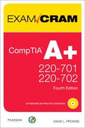
The hard disk drive (often shortened to hard drive or hard disk) contains one or more platters with a magnetic surface. Data is recorded to the disk by magnetizing ferromagnetic material directionally, basically, as 0s and 1s. The disk is usually made of a cobalt-based alloy. As the platters rotate at high speed, read/write heads store and read information to and from the disk. The heads are located on an actuator arm that arcs across the disk. Together, the arm and read/write heads are similar to the arm and needle combination of a record player. Figure 6.1 shows some of the components inside and outside of the drive.
Figure 6.1 Components of a typical hard disk drive
The hard drive depicted in Figure 6.1 is a typical Ultra ATA 3.5-inch wide drive. This hard drive, like all internal hard drives, has a data connector and power connector. On this particular drive, the data connector attaches to the motherboard (or expansion card) by way of a ribbon cable. The power connector attaches to the power supply by way of a four-wire power cable. Regardless of the type of hard drive, always make sure that the data and power cables are firmly connected to it.
PATA Versus SATA
In this corner, coming in at a maximum data throughput of 133MB/s is PATA (Parallel ATA). This was the standard for many years but has been all but phased out by SATA hard drives on most new computers. PATA hard drives are often referred to as Ultra ATA drives and sometimes as IDE drives. They transfer data in parallel, for example 16 bits (2 bytes) at a time. Currently, the maximum capacity Ultra ATA hard drive available for purchase is 750GB.
Internal PATA hard drives use the Integrated Drive Electronics (IDE) interface to transmit data to and from the motherboard. Every IDE port on a motherboard can have up to two drives connected to it. For a long time, motherboards would be equipped with two IDE ports, enabling for a maximum of four IDE devices. However newer motherboards often come with only one, limiting you to two IDE devices. The IDE ports on the motherboard and the hard drive manifest themselves as 40-pin connectors to which you can connect either a 40 or 80-wire ribbon cable. Newer IDE cables are all 80-wire; however, they look identical to the older 40-wire versions, except for the blue connector on one end that you find on many 80-wire cables. The cable has three connectors, one for the controller (often blue), one for the master drive (often black), and a connector in the middle of the cable for the slave drive (often gray). We talk more about master/slave configurations in a little bit. The IDE port on the hard drive is keyed for easy orientation. External PATA drives usually transfer data to the computer by way of USB or FireWire.
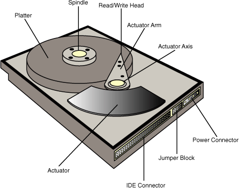
PATA hard drives accept a 4-pin Molex power connector from the computer’s power supply. The Molex connector is keyed so that it is easier to orient when connecting to the hard drive. This power cable has four wires: Red (5V), Black (ground), Black (ground), and Yellow (12V). For more information about Molex and other power connections, see Chapter 5, “Power.” Figure 6.2 shows an actual Ultra ATA hard drive’s data and power connectors.
Figure 6.2 PATA Ultra-ATA data and power connectors
There is a jumper block in between the power and data connectors. This enables you to select the configuration of the hard drive. There are usually four options, which are often labeled on the drive itself:
• Single: In a single drive configuration, no jumper shunt is needed. If you want, you can connect the jumper horizontally across two pins. Although this does not configure the drive in any way, it keeps the jumper handy for future use.
• Master: Each of the motherboard’s IDE connections enables for two drives. In a two-drive configuration on a single IDE cable, one must be set to drive 0 (master), and one must be set to drive 1 (slave). To set a drive to master, connect the jumper vertically to the correct pair of pins (for example, Western Digital drives use the center location; refer to Figure 6.2), and connect the black end connector of the IDE ribbon cable to the hard drive. The master hard drive is normally where the operating system would go.
• Slave: To set a drive to slave, connect the jumper vertically to the correct pair of pins (for example, Western Digital drives use the second position from the right), and connect the gray, middle connector of the IDE cable to the hard drive. The slave hard drive is where the bulk of the data would usually be stored.
• Cable Select: This drive mode automatically configures the drive as master or slave according to where you connect it to the IDE cable. This might be marked on the drive as CS.
There are currently seven versions of Parallel ATA, four of which you should know for the exam. These standards and their maximum data transfer rates are listed in Table 6.1.
Table 6.1 Comparison of PATA Standards.

Note
ATA-6 introduced 48-bit addressing, which allows for a maximum hard drive capacity of 144 petabytes. Previous versions had a maximum drive size of only 137GB.
ExamAlert
Know the data transfer rates for ATA-5, 6, and 7.
And in this corner, coming in at a whopping maximum data throughput of 600MB/s is SATA (Serial ATA). These drives are the most-common hard drives in use today. If you remember, the motherboard we used in Chapter 2, “Motherboards,” had six SATA ports, but only one PATA IDE port, most likely for use with optical drives. So as you can surmise, hard drives, like expansion busses and several other technologies, have gone serial. A Serial ATA drive transmits serial streams of data (one bit at a time) at high-speed over two pairs of conductors and can do so in full duplex, meaning it can send and receive simultaneously. Because SATA and PATA will not interfere with each other, you can run both simultaneously; however, by default one will not mate to the other; they are not compatible without a converter board.
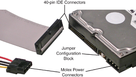
To transmit data the SATA drive uses a 7-pin flat (or right-angle) cable, as shown in Figure 6.3. Obviously, the motherboard should be equipped with one or more SATA connectors to use SATA hard drives. The other option would be to install an SATA PCIe or PCI expansion card. Most motherboards come with one or more SATA data cables. These cables are easily connected to the drive but to remove them, press down on the connector’s metal tab at the end of the cable before pulling the cable out. Only one drive can be connected to the SATA cable.
Figure 6.3 SATA data and power connectors
For power, the SATA drive utilizes a 15-pin power connector, as shown in Figure 6.3. Your power supply must be equipped with this power cable to support SATA drives. The hard drive’s power connector has a vertical tab at the right side, making for easier orientation when connecting the power cable.
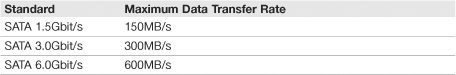
SATA 1.5 was the first generation of SATA devices. Currently, SATA 3.0 is the most common. Table 6.2 shows the different SATA versions you need to know for the exam.
Table 6.2 Comparison of SATA Standards
Note
Even newer SATA 3.0 magnetic hard disks can barely transfer data at 150MB/s; however solid-state drives come close to 300MB/s (more on solid-state later in this chapter).
Although SATA 6.0 has been ratified, that data rate has yet to be realized in the consumer market.
ExamAlert
Know the maximum data transfer rates for SATA 1.5 and 3.0.
ExamAlert
Know the major differences between PATA and SATA for the exam.
For this book, I decided to use the SATA 3.0 hard drive; specifically the Western Digital Caviar Blue WD5000AAKS. This model is an average hard drive when it comes to speed and other major specifications. The specifications that you should be interested in when purchasing a hard drive (PATA or SATA), and should know for the A+ exams, include the following:
• Capacity: Our example drive is marketed as a 500GB drive, but accessible capacity will vary depending on the environment the hard drive is used in. For example, after being formatted, this drive can normally hold 500,107MB. But in a RAID 1 mirrored environment, it can hold 490,402MB. Currently, the largest SATA drive capacity is 1.5TB.
• Data transfer rate: Because it is an SATA 3.0 drive, it has a theoretical maximum of 300MB/s; but we all know that the theoretical numbers are never actually achieved. This particular drive can sustain in the neighborhood of 120MB/s. This is sometimes also referred to as data throughput.
• Rotational speed: The platters in our example hard drive can rotate at a maximum of 7200RPM, which is common; other typical speeds for hard drives include 5400RPM and 10,000RPM.
• Cache: This drive has 16MB of cache, which is also known as a buffer. The cache on most hard drives is on-board DRAM. Compare this with CPUs that use SRAM cache that is significantly faster. Like CPUs, the hard drive’s cache helps to access frequently used information faster than if it were to get the information from the magnetic disk.
• Latency: After a track has been reached by the read head, latency is the delay in time before a particular sector on the platter can be read. It is directly related to rotational speed and is usually half the time it takes for the disk to rotate once. For example, our 7200RPM drive has an average latency of 4.2ms (milliseconds), but a 10,000RPM drive has an average latency of 3.0ms.
ExamAlert
Understand a hard drive’s specifications including capacity, data transfer rate, rotational speed, cache, and latency.
SCSI
Small Computer System Interface (SCSI) hard drives are often used in servers and power workstations that need high data throughput. You can identify a SCSI drive by the different (and usually louder) sound it makes compared to ATA drives; it’s kind of like the difference between a diesel engine and a standard car engine. SCSI standards describe the devices, controllers, cables, and protocols used to send data. Part of the beauty of SCSI is that you can have up to 16 devices including the controller. They can be internal, external, or both. For the longest time SCSI was a parallel technology, but of late serial versions such as SAS (Serial Attached SCSI) have emerged. When installing SCSI devices, it is important to remember that each end of the SCSI chain must be terminated and that each device gets its own ID, between 0 and 15 (0-7 on older SCSI chains). The controller normally gets ID 7 and has its own BIOS, known as Option ROM, in which you can configure the controller, drives, and drive arrays. A driver might need to be installed to the operating system for the SCSI controller. Table 6.3 shows a few of the current SCSI technologies you might see in the field.
Table 6.3 Comparison of SCSI Standards

ExamAlert
For the exam, know that the SCSI controller normally uses ID 7, and memorize the data transfer rates for the various SCSI Ultra versions.
Installing Hard Disk Drives
Installing hard drives is quite easy. First, make sure you employ antistatic measures and verify that the computer is off and unplugged.
Next, if it is an Ultra ATA drive (IDE), be sure to configure the jumper setting correctly. SATA drives do not need to be jumpered, unless they are coexisting with Ultra ATA drives on an IDE bus. Most internal drives are 3.5 inches, and most cases have several 3.5-inch internal bays. The drive bay might need to be removed before attaching the drive, or you might screw it directly into the chassis. Some cases have a latching screwless system. However, if you need to screw in the drive, make sure you use all four screws, and only turn the screws with a screwdriver until they are tight; don’t go any further. Try to stay away from motorized screwdrivers or other tools that might have too much torque and can possibly damage the hard drive.
After the drive is screwed in or attached to the case chassis, connect the data and power connectors. For Ultra ATA drives, the data connector is keyed. There is a tab on each end of the cable (in the middle), which corresponds to a notch on the hard drive’s port and on the motherboard’s port. In addition, these types of cables indicate the first pin (known as Pin 1) with a colored stripe on one side of the cable. Pin 1 is normally on the upper-right corner of the hard drive’s IDE port, so just match the colored stripe up to it. Or remember that the colored stripe of the IDE cable should be oriented next to the power connector. The power connector (Molex) is also keyed; it has two diagonal corners that should be oriented at the top of the connector when plugging it into the drive. Try not to force these connections; it can damage an individual pin. It should take a bit of pressure, but if it doesn’t seem right, pull the connector away, and make sure it is oriented correctly. For SATA drives, attach the data connector with the exposed metal facing up, and orient the power connector according to the tab on the right side of the hard drive’s port. Verify that both the data and power connectors are firmly secured to the drive and to the motherboard. A loose connector can cause a boot failure in the operating system.
Finally, test the drive and make sure it is recognized by the BIOS at the correct capacity. If for some reason, the BIOS doesn’t see the full capacity, check for any possible BIOS updates. Then, either install an operating system to the drive, or verify that a current operating system (on another pre-existing disk) can see the new drive at its correct capacity. Remember that a drive might show up as slightly less than its marketed amount within the operating system, depending on the environment the drive is used in.
Preventative Maintenance and Troubleshooting Hard Drives
Hard drives will fail. It’s not a matter of if; it’s a matter of when, especially when it comes to mechanical drives. The moving parts are bound to fail at some point. Hard drives have an average warranty of 3 years, as is the case with the SATA drive I use in this book. It is interesting to note that most drives last around 3 years before failing. Of course, by implementing good practices, you can extend the lifespan of any hard drive, for example:
• Turn the computer off when not in use: By doing this, the hard drive is told by the operating system to spin down and enter a “parked” state. It’s kind of like parking a car or placing a record player’s arm on its holder. Turning the computer off when not in use increases the lifespan of just about all its devices (except for the lithium battery). You can also set the computer to hibernate, standby, or simply set your operating system’s power scheme to turn off hard disks after a certain amount of inactivity, such as 5 minutes. The less the drive is in motion, the longer lifespan it will have.
• Clean up the disk: Use a hard drive cleanup program to remove temporary files, clean out the recycle bin, and so on. Microsoft includes the Disk Cleanup program in Windows. Another free program I use is called CleanUp! that you can download from the Internet after a quick Google search. By removing the “junk” from the hard drive, there is less data that the drive has to sift through, which makes it easier on the drive when it is time to defragment.
• Defragment the disk: Defragmenting, known as defragging rearranges the data on a partition or volume so that it is laid out in a contiguous, orderly fashion. You should attempt to defragment the disk every month, maybe more if you are a power user. Don’t worry, the operating system tells you if defragging is not necessary during the analysis stage. Over time, data is written to the drive, and subsequently erased, over and over again, leaving gaps in the drivespace. New data will sometimes be written to multiple areas of the drive, in a broken or fragmented fashion, filling in any blank areas it can find. When this happens, the hard drive has to work much harder to find the data it needs, spinning more, starting and stopping more; in general, more mechanical movement. It’s kind of like changing gears excessively with the automatic transmission in your car. The more the drive has to access this fragmented data, the shorter its lifespan becomes due to mechanical wear and tear. Defragmenting the drive can be done with Microsoft’s Disk Defragmenter, with the command-line defrag command, or with other third-party programs. If using the Disk Defragmenter program, you need 15 percent free space on the volume you want to defrag. If you have less than that, you need to use the command-line option defrag -f. To sum it up, the more contiguous the data, the less the hard drive has to work to access that data, thus increasing the lifespan of the drive.
ExamAlert
Know the tools that are available to defragment a hard drive.
• Scan the drive with antimalware: Make sure the computer has an antimalware program installed, which includes antivirus and antispyware. Verify that the software is scheduled to scan the drive at least twice a week. (Manufacturers’ default is usually every day.) The quicker the software finds and quarantines threats, the less chance of physical damage to the hard drive.
You may find several issues when troubleshooting hard drives:
• BIOS does not “see” the drive: If the BIOS doesn’t see the drive you have installed, you can check a few things. First, make sure the power cable is firmly connected and oriented properly. Second, verify that the correct end of the data cable is securely connected and oriented, for example on Ultra-ATA drives, the black connector on the ribbon cable should connect to the drive. The other end of the data cable should be firmly connected to the motherboard. Next, make sure that the drive is jumpered correctly. (Or not jumpered at all, if that is the scenario.) Finally, check if there is a motherboard BIOS update to see the drive; sometimes newer drives require new BIOS code to access the drive.
• Windows does not “see” a second drive: There are several reasons why Windows might not see a second drive. Maybe a driver needs to be installed for the drive or for its controller (for example a PCI SATA card or SCSI card). Perhaps the secondary drive needs to be initialized within Disk Management. Or it can be that the drive was not partitioned or formatted. Also try the methods listed in the first bullet.
• Slow reaction time: If the system runs slow, it can be because the drive has become fragmented or has been infected with a virus or spyware. Analyze and defragment the drive. If it is heavily fragmented, the drive can take longer to access the data needed resulting in slow reaction time. You might be amazed at the difference in performance! If you think the drive might be infected, scan the disk with your antivirus/antispyware software to quarantine any possible threats. It’s wise to schedule deep scans of the drive at least twice a week. More on viruses and spyware in Chapter 15, “Security.” In extreme cases, you might want to move all the data from the affected drive to another drive, being sure to verify the data that was moved. Then format the affected drive, and finally move the data back. This is common in audio/video environments, and when dealing with data drives, but should not be done to a system drive, meaning a drive that contains the operating system.
• Missing files at startup: If you get a message such as NTLDR Is Missing or BOOTMGR Is Missing, these files need to be written back to the hard drive. For more on how to do this, see Chapter 10, “Troubleshooting Windows.” In severe cases, this can mean that the drive is physically damaged and needs to be replaced. If this happens, the drive needs to be removed from the computer and slaved off to another drive on another system. Then the data needs to be copied from the damaged drive to a known good drive (which might require third-party programs such as SpinRite or Ontrack Data Recovery), and a new drive needs to be installed to the affected computer. Afterward, the recovered data can be copied on the new drive.
• Noisy drive/lockups: If your Ultra ATA or SATA drive starts getting noisy, it’s a sure sign of impending drive failure. You might also hear a scratching or grating sound, akin to scratching a record with the record player’s needle. Or the drive might intermittently just stop or lockup with one or more audible clicks. You can’t wait in these situations; you need to slave off the drive in another computer immediately and copy the data to a good drive. Even then, it might be too late. However, the aforementioned programs (SpinRite or Ontrack Data Recovery, and so on) might help recover the data.
Network Attached Storage (NAS)
Another type of hard drive storage is network attached storage (NAS). This is when one or more hard drives are installed into a device known as a NAS box that connects directly to the network. The device can then be accessed as a mapped network drive from any computer on the network. A basic example of this that I use on my network is the D-Link DNS-323. It can hold two SATA drives to be used together as one large capacity or in a RAID 1 mirrored configuration for fault tolerance. RAID 1 Mirroring means that two drives are used in unison, and all data is written to both drives, giving you a mirror or extra copy of the data, in the case that one drive fails. RAID levels 0, 1, and 5 are covered in Chapter 8, “Configuring Windows.” It connects to the network by way of an RJ45 port that is rated at 10/100/1000Mbps. Of course, there are much more advanced versions of NAS boxes that would be used by larger companies.
Floppy Disk Drives
As we mentioned before, floppy drives are not nearly as common as they were 10 years ago; in fact, most computers don’t come with a floppy drive at all. However, some businesses might need them to access older data or programs, and technicians use them to start up a computer with special boot disks. Due to this, there is a chance you might see a question on them on the exam.
Floppy Drive Basics
The standard floppy drive is known as a 3.5-inch 1.44MB floppy drive. Historically, this has been the A: drive and possibly the B: drive in a computer. These drive letters are reserved for floppy drives and other devices; now you know why operating systems use C: by default! The floppy drive uses a “mini” floppy power connector (shown in Chapter 5), also known as Berg, and a 34-pin keyed data cable that connects to the motherboard, if your motherboard supports it.
The floppy drive is known as removable media because the floppy disks are inserted into the drive. The most common of these disks has a 1.44MB capacity. Keep in mind that you can store only 1.38MB of data to these disks due to formatting and because the boot sector takes up a small amount of space on the disk. Floppy disks are normally formatted using the FAT12 file system.
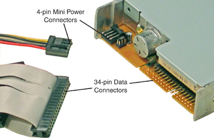
Floppy drives are installed much the same way as hard drives: They are screwed into the chassis of the case, and data and power cables connect to the floppy ports; these ports are shown in Figure 6.4. The mini power cable has a linear plastic tab that needs to face up when you connect the cable to the drive.
Figure 6.4 Floppy data and power connectors
Floppy Drive Troubleshooting and Boot Disks
As always, make sure that the data and power cables firmly connect to the floppy drive and to the motherboard. A floppy drive fails if the data connector is connected upside down, which is possible because many floppy drive’s data ports are not keyed. You will know if the data cable is upside down because the floppy drive’s activity light will remain on. If a disk is placed in the drive in this state, it will be erased and/or damaged. If the floppy drive doesn’t work at all, ensure that the BIOS has the floppy drive enabled. Otherwise, floppy drives are quite resilient and last a long time.
Examples of boot disks that a technician might use include Windows startup disks, to boot/repair or install a Windows computer; antivirus boot disks, to scan the boot sector of a hard drive; BIOS Flash boot disks, to update the BIOS on a computer; and specialized third-party boot disks, to repair a computer, recover data, and so on. If you plan to boot from a floppy disk, verify that the floppy drive is first in the BIOS boot order.
Tape Drives
Tape drives are devices primarily used for archival or backup of data. These devices use removable media in the form of magnetic tape cartridges, which are inserted into the tape drive. Usage of tape drives has declined greatly in recent years due to the advent of writable optical media; however, you might still see some devices in use.
The tape drive is rated in one of two ways: native capacity, for example 100GB; and compressed capacity, for example 200GB. As you can see, compressed capacity will normally be at a 2:1 ratio compared to native capacity. A common example of a tape drive is Quantum’s Digital Linear Tape (DLT) and the higher capacity Super DLT.
The tape drive can be internal or external. If it is internal, it might connect to a SCSI controller card or to an IDE port. If external, you might see it connect to a SCSI port, USB, IEEE 1394, or the older parallel port.
The driver for the tape drive must be installed, and a tape drive must be used with backup software. Some drives come with their own third-party software, or you can use Windows’ NTBackup. Be careful with these programs. Quite often, they backup all the data into one big compressed file, for example NTBackup backs up everything you select into one file with the .bkf extension. Be sure to use the verify option when backing up data, and consider running a test backup and restore when you first start using a tape drive to verify it works properly.
Other deprecated backup technologies related to tape drives include products from Iomega such as the ZIP or JAZ disk technology, or the SuperDisk technology. Again, these and tape drives have been all but phased out due to the popular usage of optical storage and other medias.
Cram Quiz
Answer these questions. The answers follow the last question. If you cannot answer these questions correctly, consider reading this section again until you can.
1. What is the maximum data transfer rate of SATA 1.5?
![]() A. 1.5Mbps
A. 1.5Mbps
![]() B. 300MB/s
B. 300MB/s
![]() C. 150MB/s
C. 150MB/s
![]() D. 1.5GB/s
D. 1.5GB/s
2. Which of these is the delay it takes for the hard drive to access a particular sector on the disk?
![]() A. Actuator
A. Actuator
![]() B. Latency
B. Latency
![]() C. Lag
C. Lag
![]() D. Propagation
D. Propagation
3. What should you do first to repair a drive that is acting sluggish?
![]() A. Remove the drive and recover the data.
A. Remove the drive and recover the data.
![]() B. Run Disk Cleanup.
B. Run Disk Cleanup.
![]() C. Run Disk Defragmenter.
C. Run Disk Defragmenter.
![]() D. Scan for viruses.
D. Scan for viruses.
4. How much data can an Ultra ATA/100 drive transfer per second?
![]() A. 133MB
A. 133MB
![]() B. 266MB
B. 266MB
![]() C. 150MB
C. 150MB
![]() D. 100MB
D. 100MB
5. How many pins are there in a SATA drive’s data and power connectors?
![]() A. 40 and 4
A. 40 and 4
![]() B. 8 and 16
B. 8 and 16
![]() C. 7 and 15
C. 7 and 15
![]() D. 80 and 4
D. 80 and 4
6. What kind of cable does a floppy drive use?
![]() A. 40-pin IDE
A. 40-pin IDE
![]() B. 80-pin IDE
B. 80-pin IDE
![]() C. 34-pin IDE
C. 34-pin IDE
![]() D. 168-pin IDE
D. 168-pin IDE
7. What is the maximum data transfer rate of an Ultra3 SCSI device?
![]() A. 320MB/s
A. 320MB/s
![]() B. 160MB/s
B. 160MB/s
![]() C. 640MB/s
C. 640MB/s
![]() D. 300MB/s
D. 300MB/s
8. In a two drive IDE configuration, drive 0 would be the __________, and drive 1 would be the ____________.
![]() A. Slave, master
A. Slave, master
![]() B. Cable select, slave
B. Cable select, slave
![]() C. Slave, single
C. Slave, single
![]() D. Master, slave
D. Master, slave
Cram Quiz Answers
1. C. SATA 1.5 can transfer a maximum of 150MB/s, though most devices won’t ever attain that maximum. The standard specifies the transmission of 1.5Gbps (notice the lower case ‘b’ for bits); 300 MB/s is the data transfer rate of SATA 3.0.
2. B. Latency is the delay it takes for the hard drive to access the data; it is directly related to the rotational speed (RPM) of the disk.
3. C. Attempt to defragment the disk. If it is not necessary, Windows lets you know. Then you can move on to other options such as scanning the drive for viruses.
4. D. ATA/ATAPI 6 drives can transfer 100MB/s maximum. These drives are also known as Ultra ATA/100. ATA/ATAPI 7 drives can transfer 133MB/s. SATA 1.5 drives can transmit 150MB/s, and PCI can transfer 266MB/s.
5. C. The SATA drive uses a 7-pin data connector and a 15-pin power connector. Ultra ATA IDE hard drives have a 40-pin data connector and 4-pin power connector. The IDE drive’s cable might have 80 conductors or wires, but it still physically connects through 40 pins.
6. C. The floppy drive uses a 34-pin ribbon cable to transfer data. IDE hard drives use a 40-pin ribbon cable; 168-pin refers to the amount of pins in SDRAM.
7. B. Ultra3 SCSI can transfer a maximum of 160MB/s. Ultra-320 SCSI can transfer 320MB/s, Ultra-640 can transfer 640MB/s, and SAS (Serial Attached SCSI) and SATA 3.0 can transfer 300MB/s.
8. D. In PATA IDE two-drive configurations, drive 0 would be the master and drive 1 would be the slave. Cable select is a drive mode that autoconfigures drives as master or slave depending on their cable position. Single means a single drive configuration with no configuration necessary.
Optical Storage Media
The three main types of optical media in use today are Compact Discs (CD), Digital Versatile Discs (DVD), and Blu-Ray discs. These discs have a variety of functions, including audio, video, application, data, and so on. Some discs can be read from, and some can also be written to. Finally, some discs can be rewritten to as well. It all depends on which media you use. Now there are a lot of different versions of optical media; let’s try to organize them so that they will be easier to remember. We start with the most familiar, the compact disc.
ExamAlert
You’ve probably noticed by now that most magnetic media is known as “disk” and optical media is known as “disc.” Keep this in mind for the exam.
Compact Disc (CD)
A Compact Disc (CD) is a flat, round, optical disc used to store music, sounds, or other data. It can be read from a compact disc player. For example, audio CDs can be played on a compact disc player that is part of a stereo or a computer. However, data CDs can be read only from CD-ROM drives that are part of, or externally connected to, a computer. The A+ exam focuses on data CDs, so let’s talk about some of the different data CD technologies.
Data CD Technologies
The most common acronym that comes to mind is the CD-ROM, compact disc-read-only memory. Data is written to a CD-ROM in a similar way that audio is written to a music CD; a laser shines on the reflective surface of the CD and stores data as a plethora of microscopic indentations known as lands and pits. These are the types of CDs you get when you purchase a computer program or game. They can be read from but not written to, and can be read only from a compatible CD-ROM drive. CD-ROM drives are rated in read speeds, for example 48x. The x equals 150KB/s. So to calculate a CD-ROM drive’s maximum read speed, you multiply the number preceding the x by 150KB. In this example, this would be 48 x 150KB = 7.2MB/s. Most CD-ROM drives connect via IDE. Chances are the IDE connection has a maximum data transfer rate of 100MB/s, plenty for a CD-ROM running at 48x.
Over time, the technology to write to CDs was developed, enabling users to store information to CD that they would previously store on floppy disks or Zip drives. A typical CD can hold up to 700MB of data, although there are 650MB, 800MB, and other versions available. Table 6.4 describes the two most common recordable technologies.
Table 6.4 Comparison of CD Recording Technologies
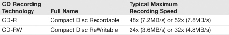
Most optical drives that you can purchase for a computer today have all three compact disc functions. They can read from CD-ROMs, write to CD-Rs, and write/rewrite to CD-RWs. Usually, the read speed and CD-R speed are the same. Because CD-Rs are extremely inexpensive, this technology took off as an archival method; it was a massive nail in the coffin for technologies such as tape backup, Zip/Jaz drives, and of course floppy disks.
ExamAlert
Know the difference between CD-ROM, CD-R, and CD-RW.
Although there are SATA and SCSI CD-ROMs, the typical CD-ROM drive is IDE and has the same types of connectors as an Ultra ATA IDE hard drive: 40-pin data connector, 4-pin power connector (Molex), and a jumper block to set the CD-ROM drive to either master or slave. Figure 6.5 displays these connectors with the CD-ROM set to slave. It also displays the stereo audio out that connects to a sound card or to the motherboard if the sound card is integrated. This enables you to play and hear audio CDs on the CD-ROM drive.
Figure 6.5 CD-ROM drive connectors

CD-ROM discs are known as removable media; however the drive is normally fixed in the computer. It installs much like an IDE hard drive. One notable exception is that most CD-ROM drives are 5.25-inches wide. So they need to be installed to one of the larger bays in a case that has an opening on the front; this way the drive tray is accessible. Most CD-ROM drives can also play audio CDs and have a volume knob on the front. In addition, many drives have a pinhole near the volume knob. This small hole is for when a CD (or the tray) gets jammed. Use a paper clip and insert it into the hole in an attempt to free the tray and CD.
Digital Versatile Disc (DVD)
For data, Digital Versatile Discs, also known as Digital Video Discs, are the successor to CDs for a variety of reasons. First, they can be used to play and record video. Second, they have a much greater capacity than CDs. This is because the pits etched into the surface of the DVD are smaller than CD pits (.74 micrometers compared to 1.6 micrometers). Also, DVDs can be written to faster than CDs. So, there are read-only DVDs and writable DVDs; however, there are a lot more variations of DVDs than there are CDs. Table 6.5 describes some of the DVD-ROM (Digital Versatile Disc-Read-Only Memory) versions, specifications, and differences starting with the common DVD-5 version.
Table 6.5 Comparison of DVD Technologies

The most common DVD is currently the single-sided, single-layer (SS, SL) DVD-5 technology that can store 4.7GB of data. But some DVDs can be written to two sides (known as dual-sided or DS); simply flip the DVD to access the information on the other side. Layers however work differently. A DVD with two layers (known as dual layer or DL) incorporates both layers onto a single side of the disc. The second layer is actually underneath the first one; the DVD laser reads this second layer by shining through the first semitransparent layer. By combining dual-sided and dual-layer technologies together, you end up with a DVD that can store up to 17GB of data (known as DVD-18) at 8.5GB per side.
ExamAlert
Know the capacity of DVD-5 for the exam.
Once again, for DVD-ROMs, and recordable DVDs, the most common by far is DVD-5. Typically a DVD drive reads these discs at 16x. However, the x in DVD speeds is different than the x in CD-ROM speeds. When it comes to DVDs, the x means approximately 1.32MB/s or about nine times the core CD speed. So, a typical 16x DVD is equal to 21MB/s. Typically, a DVD drive will read at 16x, record once at 22x or 24x, and rewrite at 6x or 8x. Table 6.6 gives a description of the different types of recordable DVDs.
Table 6.6 Comparison of DVD Recordable Technologies

There is a slight difference in capacity between DVD− and DVD+ as you can see in Table 6.6. DVD− was developed by Pioneer and approved by the DVD Forum, whereas DVD+ was developed by a group of corporations headed up by Sony. Likewise, DVD−RW was developed by Pioneer and approved by the DVD Forum, and DVD+RW was developed by the same group of corporations that developed DVD+R; this group is now known as the DVD+RW Alliance. It’s probably not important to know all this for the exam, because most DVD drives support all these formats. However, always check your drive to be sure before purchasing recordable DVDs.
Like most CD-ROM drives, the bulk of DVD drives connect via IDE, although this is changing slowly. IDE models have the same connections as IDE CD-ROMs and IDE hard drives: 40-pin data connector and 4-pin Molex power; they are jumpered using the same method (single, master, or slave); and are installed in the same manner, within the same 5¼ inch bay as CD-ROM drives. However, there are SATA DVD drives (the Samsung model I purchased for this book is SATA), and it connects the same way as other SATA devices. Most DVD drives are known as combo drives, meaning they can read and write to CDs and read DVDs (DVD-ROM drive), write DVDs (DVDR), and rewrite DVDs (DVDRW). The Samsung drive mentioned earlier does all these things, plus it includes the LightScribe technology that can create labels by etching text and graphics onto specially coated CDs and DVDs.
Because they are relatively cheap, DVD drives, like CD-ROM drives, are usually replaced if they fail. It could easily cost a company more money to try to repair a DVD drive, instead of simply purchasing one for between $10 to $20. However, if a problem does occur, remember to check the obvious; it takes only a few minutes. For example, if a DVD (or CD) drive tray won’t open, press the eject button one time and wait. It can take a few moments for the DVD to spin down before opening. Then press it a few more times waiting a couple of moments after each time. You can also try to eject the disc from within the operating system. To do this, go to Windows Explorer, and right-click the drive in question; then select Eject. If this doesn’t work, you can try to restart the computer and try the eject options again. Don’t forget the pinhole near the open button. You can slide a paperclip in there to get the tray to open. Sometimes, DVD drives have been installed with incorrect screws that are too long. This can cause damage to the drive tray. Finally, make sure that the drive is getting power! A loose Molex or SATA power connector results in the tray not opening or closing.
Blu-Ray
In 2008 the Blu-Ray Disc Association won the high-definition battle against Toshiba’s HD DVD. Currently Blu-Ray is the standard for high-definition video. It is used by high-def movies, PlayStation 3 games, and for storing data, up to 50GB per disc, ten times the amount of a typical DVD-5 disc. The standard disc is 12cm (same size as a standard DVD or CD), is single-sided, and has a capacity of 50GB. The mini disc is 8cm, single-sided, and has a capacity of 15.6GB. Drive speeds range from 1x to 8x (with more undoubtedly on the way). 1x is equal to 36Mbps or 4.5MB/s. 8x would be eight times that core amount, which is 288Mbps or 36MB/s, which is superior to DVD write speeds. The reason you see read speeds in bits is because Blu-Ray players normally transfer data serially via SATA connections.
To play movies, games, or read the data from a Blu-Ray disc, the computer must have a compatible Blu-Ray drive. Currently, there are combo drives on the market that can read Blu-Ray discs (but not write to them, these are known as BD-ROMs), read/write DVDs, and read/write CDs.
Like CD and DVD drives, Blu-Ray drives for the PC are installed into a 5.25-inch bay in the computer case. However, Blu-Ray drives almost always have SATA connections. Keep this in mind if you upgrade a computer; the power supply needs an extra 15-pin SATA power connector, and the motherboard (or SATA card) needs to have one free SATA data port.
Cram Quiz
Answer these questions. The answers follow the last question. If you cannot answer these questions correctly, consider reading this section again until you can.
1. What does the x refer to in Compact Disc technology?
![]() A. 150KB/s
A. 150KB/s
![]() B. 1.32MB/s
B. 1.32MB/s
![]() C. 133MB/s
C. 133MB/s
![]() D. 4.5MB/s
D. 4.5MB/s
2. What type of interface does a DVD drive typically connect to?
![]() A. PCMCIA
A. PCMCIA
![]() B. SATA
B. SATA
![]() C. IDE
C. IDE
![]() D. SCSI
D. SCSI
3. What is the maximum capacity of a Blu-Ray disc?
![]() A. 700MB
A. 700MB
![]() B. 4.7GB
B. 4.7GB
![]() C. 17GB
C. 17GB
![]() D. 50GB
D. 50GB
4. If a user wanted to write information more than one time to a DVD, which type should you recommend? (Select all that apply.)
![]() A. DVD-R
A. DVD-R
![]() B. DVD−RW
B. DVD−RW
![]() C. DVD+RW
C. DVD+RW
![]() D. DVD+R
D. DVD+R
Cram Quiz Answers
1. A. The x in CD technology is equal to 150KB/s. A 1x drive can read or write 150KB/s, a 2x drive can read or write 300KB/s, and so on. 1.32MB/s is the 1x speed of a DVD. 133MB/s is the maximum data transfer rate of an Ultra ATA-7 connection, and 4.5MB/s is the 1x speed of a Blu-Ray disc.
2. C. DVD and CD drives typically connect to the motherboard by way of an IDE interface, but SATA interfaces are becoming more common.
3. D. Standard 12cm Blu-Ray discs have a maximum capacity of 50GB. A typical CD capacity is 700MB; 4.7GB is the capacity of the common DVD-5, and 17GB is the capacity of a DVD-18 (using both sides).
4. B and C. DVD−RW and DVD+RW are the ReWritable versions of DVDs. DVD-R and DVD+R are write-once formats.
Solid-State Storage Media
There are many types of solid-state media. Solid-state media by definition is media with no moving parts, based on the semiconductor. Most of these are implemented as large amounts of nonvolatile memory, known as flash memory and are located on a card or drive. Remember that nonvolatile means any data on the device is retained, even if the device is not receiving power. Examples of solid-state cards include SD cards and CompactFlash cards. Examples of solid-state drives include USB flash drives, internal SATA drives (that can take the place of a magnetic hard drive), and even PCIe drives (that are integrated into a PCIe card). In this section we focus on three types of solid-state flash media: USB flash drives, SD cards, and CompactFlash.
USB Flash Drives
The USB flash drive is probably the most familiar of all flash media. Also known as USB thumb drives, they are often retractable and can be carried on a keychain. Figure 6.6 shows an example of a USB flash drive connected to a laptop’s USB port.
Figure 6.6 A typical USB flash drive in a laptop’s USB Port
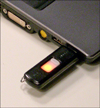
Notice that the USB flash drive is lit, indicating that it is connected to the laptop’s USB port and ready to transfer data. In this scenario, the drive shows up as a volume within Windows Explorer, usually named Removable Disk. Connecting the drive is easy; just find an open USB port. But remember that you should safely remove hardware in the operating system before disconnecting the drive physically. If you don’t, it can cause electrical irregularities that can damage the data on the drive. In Windows, you can either double-click the Safely Remove Hardware icon in the System Tray, or right-click it to bring up the Safely Remove Hardware window. From there click Stop to shut down power to the selected USB device. Then it can be safely removed from the physical USB port. The icon appears as a device with a green arrow above it pointing to the left and slightly down. Sometimes, if you right-click the icon and simply click Safely Remove Hardware, the device will be turned off, and the icon disappears. If your USB device has a light, make sure that light is off before physically removing the device.
ExamAlert
Remember to safely remove USB flash drives in the operating system before physically disconnecting them.
Tip
Sometimes, a USB or other flash-based solid-state device can’t be removed with the Safely Remove Hardware option in Windows. If this happens, consider shutting down the computer before physically disconnecting the device to avoid data corruption or loss.
The advantages of a USB flash drive are obvious. For example, the drive in Figure 6.6 is an 8GB flash drive that costs in the neighborhood of $20. That is a good cost-to-MB ratio for an instantly rewritable media. It would take 2 standard DVD-RWs, or 10 standard CD-RWs, or 5,000 floppy disks to match that capacity. The best part is that no formatting is necessary, and data can simply be dragged and dropped to the drive, unlike CDs and DVDs that need to be burned. In addition, USB flash drives’ read/write speed is comparable to DVD technology, averaging about 30MB/s reads and 15MB/s writes. Finally, it’s small: it has a little footprint. What I used to carry around in a CD case is now on one flash drive on my keychain. Plus, newer flash drives are ranging all the way up to 64GB and beyond and have a much longer lifespan than just a few years ago. They can also be used to boot or install operating systems.
Let’s talk about the type of memory used in this solid-state device: NAND flash memory is the core of a USB flash drive. This memory is broken up into blocks that are generally between 16KB and 512KB. Know that a USB flash drive’s blocks can be written to only so many times before failures occur. With some flash drives manufacturers estimate this at up to 1 million write/erase cycles, or 10 years of use. However, just like hard drives will never attain their maximum data transfer rate, it is doubtful that a flash drive will ever attain that maximum amount of write/erase cycles. In addition, the amount of years is subjective; it all depends on how often a user works with the flash drive. Basically, if you take the number given by the manufacturer and cut it in half, you should be in good shape, unless you are an extreme power user. Now back to NAND flash failures: Because this type of memory incurs a small amount of faults over time (as opposed to NOR flash, which should remain free of faults), a method known as Bad Block Management is implemented, which maintains a table of the faulty blocks within the USB flash device, making sure not to save data to those blocks. Blocks are broken down further into pages, which can be between 512 bytes and 4KB. Each page has error detection and correction information associated with it. All this is done to prolong the lifespan of devices using NAND memory.
Normally, USB flash drives are shipped in a formatted state, usually FAT32, possibly FAT16. This enables the drive to be accessed by just about any computer on the market and makes for easy repair of corrupted files with utilities such as ScanDisk. These drives can also be formatted as NTFS if the user wants. Sometimes NAND flash devices such as USB flash drives act up intermittently. Unless the card has failed completely, a quick reformat usually cures the flash drive of its woes. Just be sure to backup your data first! This method applies to other forms of solid-state NAND-based media.
Troubleshooting of these devices is not usually necessary, but you might see a couple of issues:
• Sometimes USB flash drives and other solid-state media can conflict with each other, prompting you to change the drive letter of one or more devices within Disk Management.
• In some cases, Windows XP SP2 will not “see” your device no matter what you do. Microsoft has released a hotfix for these types of USB controller issues. See article 892050 at http://support.microsoft.com for the download. Microsoft also has a USB Flash Drive Manager for Windows XP to aid in backing up and restoring information to and from USB flash drives.
In general, make sure that your operating system has the latest service pack and updates installed. For more information on USB, see Chapter 12, “Video, Audio, and Peripherals.”
Some USB flash drives are preloaded with software that can restore data and possibly secure transferred data. The only problem with USB flash drives is that although they are small, they can’t fit inside most digital cameras, cell phones, PDAs, and other hand-held devices. For that, you need something even smaller: Enter the SD card.
Secure Digital Cards
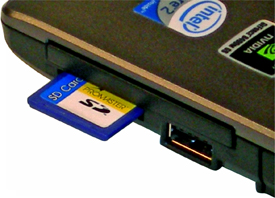
Secure Digital cards (SD cards), for the most part, are technically the same type of device as a USB flash drive. They are solid-state, use NAND memory, and have most of the same pros and cons as a USB flash drive. The difference is the form factor of the device and because of this, the usages. Instead of connecting an SD card to a USB port, it slides into a memory card reader. There are specialized memory card readers for SD cards only, and other readers that can read multiple formats of cards. Like USB flash drives, be sure to use the Safely Remove icon in Windows before physically removing the SD card. There are three sizes of SD cards: standard, miniSD, and microSD, each smaller than the last. You can still find many standard size SD cards used in cameras and some other devices but note that most cell phones and PDAs use microSD cards for additional memory. Figure 6.7 shows a full-size SD card and a microSD card. Figure 6.8 shows the standard SD card inserted into a laptop’s memory card reader slot. Note that this slot can accommodate SD cards or smaller but nothing bigger than an SD card.
Figure 6.7 A typical microSD card (left) and a standard SD card (right)
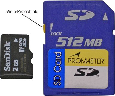
Figure 6.8 A standard SD card inserted in a laptop’s Memory Card Reader.
Standard SD cards have capacities up to 4GB. High-capacity (SDHC) cards range up to 32GB. An upcoming specification, eXtended Capacity (SDXC), will supposedly have a maximum capacity of 2TB. When it comes to data transfer rate, SD cards are divided into three different classes: SD Class 2, 4, and 6, each with a different range of speeds. Class 6 is the fastest and ranges between 6 and 45MB/s. Some SD cards, like the one in Figure 6.7, have a write-protect tab within the notch on the left side of the card. Sliding the tab down “locks” the card so that it can be read from but not written to.
A derivative of SD is the Secure Digital Input Output (SDIO) card. This takes the capabilities of an SD card and merges them with the functionality of an I/O device. Some PDAs use this technology to integrate GPS, WLAN, Bluetooth, and many other types of radio technologies. SDIO cards do not work in standard SD card slots, but standard SD cards can be read in SDIO slots.
Note
Don’t confuse an SDIO card with a SIM (Subscriber Identity Module) card. A SIM card identifies the user/subscriber of a phone or PDA and allows the telecommunications company to lock the phone to that SIM card. The SIM is a slightly different size than the SD and SDIO cards.
CompactFlash Cards
CompactFlash (CF) is another kind of solid-state memory that can be used in a variety of formats, the most common of which is the CompactFlash card. These are categorized as either Type I cards that are 3.3-mm thick and Type II cards that are 5-mm thick. These cards are larger than SD cards and are often used in hand-held computers, high-end cameras (Type I) and for Microdrives (Type II).
Common capacities for CF cards max out at about 32GB; however, the technology can go as high as 137GB. The cards are formatted by the manufacturer as either FAT32 or FAT, in the same manner as USB flash drives and SD cards. Like USB flash drives and SD cards, CF cards have a built-in ATA controller that makes them appear as a hard drive to the operating system; they show up as a volume within Windows Explorer. In the past CompactFlash cards used NOR memory but are typically NAND-based nowadays, like USB flash drives and SD cards. In general, CompactFlash has a lot of the same characteristics as SD cards. For example the data transfer rate ranges from 6 to 45MB/s. CF speeds have increased with each new version, starting with the original CF and moving on to CF High Speed, CF 3.0, and CF 4.0.
CompactFlash cards have taken on a new meaning as well; you can find various CF cards that have built-in Ethernet, WLAN, Bluetooth, GPS, and other technologies. The CF card is identical to a PC card from an electrical standpoint, so you see the same types of technologies in a CF card as you would in a PC card. You can use a CF card directly within a PCMCIA slot with the right adapter. For more information on PC cards and PCMCIA, see Chapter 11, “Laptops.”
Cram Quiz
Answer these questions. The answers follow the last question. If you cannot answer these questions correctly, consider reading this section again until you can.
1. What should you do before physically removing a USB flash drive? (Select the best answer.)
![]() A. Turn it off.
A. Turn it off.
![]() B. Shut down Windows.
B. Shut down Windows.
![]() C. Format the drive.
C. Format the drive.
![]() D. Use the Safely Remove icon.
D. Use the Safely Remove icon.
2. How is most solid-state media formatted by the manufacturer?
![]() A. As FAT32
A. As FAT32
![]() B. As NTFS
B. As NTFS
![]() C. As FAT16
C. As FAT16
![]() D. As FAT12
D. As FAT12
3. What is the main difference between SD and SDIO?
![]() A. SD cards are faster.
A. SD cards are faster.
![]() B. SDIO cards incorporate input/output functionality.
B. SDIO cards incorporate input/output functionality.
![]() C. SD cards incorporate input/output functionality.
C. SD cards incorporate input/output functionality.
![]() D. SDIO cards can identify a user’s cell phone.
D. SDIO cards can identify a user’s cell phone.
4. What kind of controller is built into a CF card?
![]() A. SATA
A. SATA
![]() B. IDE
B. IDE
![]() C. ATA
C. ATA
![]() D. SCSI
D. SCSI
Cram Quiz Answers
1. D. In Windows you can either double-click the Safely Remove Hardware icon in the System Tray or right-click it to bring up the Safely Remove Hardware window. From there click Stop to shut down power to the device. Shutting off Windows is another possibility but not the best answer because it is time-consuming.
2. A. FAT32 is the most common file system used on solid-state media such as USB flash drives, SD cards, and CF cards. FAT16 is another possibility but less common. Users have the option to reformat most of these devices as NTFS if they want.
3. B. SDIO cards integrate I/O functionality into a standard SD card. They are basically the same speed as SD cards. Answer D is referring to SIM cards, not SDIO cards.
4. C. An ATA controller is built into the CF card and many other solid-state technologies.
Additional Reading and Resources
Additional A+ resources: http://www.davidlprowse.com/aplus.
Mueller, Scott. Upgrading and Repairing PCs. Que.