Chapter 2. Motherboards
Without a doubt, the motherboard is the foundation of the computer. Everything connects to the motherboard, and all data is transferred through this matrix of circuitry.
In this chapter we delve into the components that make up the motherboard, the various types of motherboard form factors, the ports and interfaces you find on the face and the side of the motherboard, and the Basic Input Output System (BIOS) and show proper methods for installing and troubleshooting motherboards.
Motherboard Components and Form Factors
Over the years I have found that if a student is going to lack knowledge in one area, it’s quite often going to be the motherboard. Unfortunately, this is one of the key elements in a computer system. It’s the starting point for a quick and efficient computer. Because it connects to everything in the computer system, you need to know many concepts concerning it. Let’s begin with the parts that make up the motherboard.
Motherboard Components
You don’t need to know every single chip and circuit that resides on the motherboard. Generally, if a motherboard fails, which is uncommon, the entire board needs to be replaced. However, you do need to know the main components, interfaces, and ports of a motherboard and have some knowledge of how it transmits data. This ensures compatibility of components when you design your own system or connect replacement or additional devices to a motherboard. It also enhances your troubleshooting skills—when the time comes...muhahahah!
Main Components
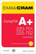
I decided to build a new computer for this book (and for me I suppose) and wanted to use fairly new components. Not the latest or most expensive mind you but still current, decent parts that reflect the type of components you see in the field now and for a year or two to come. For the motherboard, I chose the Intel DP35DP. It is part of the media series of motherboards. (It wasn’t because it has my initials, I swear!) Figure 2.1 shows this motherboard with callouts to the main components you need to know for the exam.
Figure 2.1 Intel DP35DP motherboard components
You might have noticed that this motherboard meets all the characteristics of the ATX form factor; it is indeed an ATX motherboard that we speak more of later in this chapter. And don’t worry if you are confused about one or two of the components; we cover each of these as we progress through this book. Processors are covered in more depth in Chapter 3, “The CPU,” RAM is covered in Chapter 4, “RAM,” power is covered in more depth in Chapter 5, “Power,” and SATA and IDE are covered in Chapter 6, “Storage Devices.” We talk about the remainder of the listed components within this chapter.
Product guides usually accompany a device. But if you don’t have one and want more information about the components of this or any motherboard, consider grabbing a technical document from the manufacturer’s website. “Go to the source!”—that’s what I always tell my students. For example, for this motherboard see the following link: http://www.intel.com/products/desktop/motherboards/DP35DP/DP35DP-overview.htm. This has all the information you can possibly want about the motherboard. If you were to click on Technical Documents, you can download a PDF of the product guide (among other documents) that includes diagrams, descriptions, installation procedures...the whole nine yards. Now I know you have seen a lot of acronyms (and there are a slew more coming), but here’s a vital one for you: RTM, “Read the Manual!” It helps when installing, configuring, and troubleshooting a device. As far as Intel goes, trust in these guys, they are some of the greatest technical documentation specialists on the planet.
ExamAlert
Go to the manufacturer’s website for product documentation.
Chipsets and Busses
In a general sense, the chipset is the motherboard, incorporating all the controllers on the motherboard; many technicians refer to it in this way. But in the more specific sense, the chipset is composed of two main components:
• Memory Controller Hub (MCH): On Intel motherboards this provides the connection between the processor (also known as the CPU), the RAM, and some PCI Express devices and handles the communications between them. Historically it has been known as the MCC or memory controller chip and is informally referred to as the northbridge. The MCH is used by devices that require a high speed of data transfer. It is important to note that on many AMD-based motherboards, this chip doesn’t connect to the RAM; instead the RAM is accessed directly by the processor; therefore, on those AMD-based motherboards, this chip is simply referred to as the northbridge.
Note
Newer Intel Core i7 setups have a redesigned chipset that uses the Input/Output Hub (IOH) in place of the MCH. The memory controller portion is integrated to the CPU, so the IOH has connections only to the CPU and to some PCI Express devices. However, this technology is fairly new, so you will probably not see questions on the exam about it but be ready to see it in the field!
• I/O Controller Hub (ICH): This provides the central connection point between all the secondary systems such as USB, FireWire, hard drives, and so on. It connects to the MCH through the Direct Media Interface (DMI), which is a high-speed point-to-point interconnection for the two hubs. The ICH is also known as the southbridge.
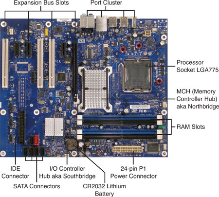
Another document available to us is the Technical Product Specification PDF. Technically this document is much more in depth, even bordering on the hypertechnical! It includes a schematic of the motherboard that shows the chipset, busses, circuitry, and chips of the motherboard and how they interconnect. From this we can see that the chipset on our motherboard is called the P35 Express chipset and contains the Intel 82P35 MCH and the Intel 82801R ICH. Figure 2.2 gives a rough idea of the connections between these hubs and the rest of the motherboard.
Figure 2.2 Intel P35 chipset connections
The previous figure and text gives a specific example of a chipset. However, because there are several different types of processors and manufacturers of processors, the two main chips in the chipset might be referred to as different things. In general, you can get away with using the terms northbridge, which basically connects to the CPU, and southbridge, which connects all the secondary systems.
A quick word on busses. A bus can be one wire (serial) or a group of wires working in unison (parallel) that carry data from one place to another. Parallel busses are normally designed in multiples of eight wires. That is the simple explanation and should be enough for the exam.
Three major busses (you can think of them as highways) lead to and from the MCH:
• Front Side Bus (FSB): This connects the MCH to the processor (CPU) socket. On our motherboard it is rated for 1,333, 1,066, or 800 MHz, which depends on what type of processor used. This bus is also referred to by Intel as the system bus in some of its documentation. When deciding on a processor, make sure that it can run at one of the FSB speeds prescribed by the motherboard. It also needs to be compatible with, and adhere to the wattage maximum, of the motherboard’s socket. (Newer Core i7 systems use a different type of bus known as the QuickPath Interconnect [QPI] instead of the FSB.)
Note
The speed of the bus is rated in Hertz (Hz), a unit of frequency defined as a number of cycles per second. In this case, our front side bus can go as high as 1,333MHz or 1.33 billion cycles per second (if it is not overclocked!). For a primer on Hertz, bits, and bytes, access my website: http://www.davidlprowse.com/aplus.
• Memory Bus: This set of wires connects the MCH to the RAM slots. It has also been referred to as the address bus.
• PCI Express x16 Interface: This connects the MCH to the x16 PCIe slot used for video; usually there is only one of these slots on a motherboard.
The front side bus and memory bus are parallel; however, PCI Express works as a group of serial busses.
The ICH provides connectivity to all the secondary busses, some of which are parallel busses (IDE, Audio) and some of which are serial busses (USB, SATA, IEEE 1394, and lesser PCIe slots).
The two types of drive technologies that have ports on the face of our motherboard are IDE and SATA, which connect to the I/O Controller Hub:
• IDE: Integrated Drive Electronics interfaces (as shown in Figure 2.1) have 40 pins. They utilize the Parallel ATA (PATA) standard that currently specifies a maximum data transfer rate of 133MB/s. These bytes of information are transferred in parallel, for example 8 bits at a time. Hard drives, CD-ROM drives, and DVD drives can connect to IDE ports. The IDE connector is 40 pins, but depending on the version, the cables used can have 40 or 80 conductors.
• SATA: Serial ATA is quickly eclipsing IDE. As you can see in Figure 2.1, there is only one IDE port, but there are six 7-pin SATA ports (one of which is for external connections). The reason for this is speed. Even though SATA sends data in a serial fashion, or one bit at a time, it is faster than IDE. The first generation of SATA is rated at 1.5Gbps (notice the lower case b indicating bits), equal to roughly 150MB/s. Second generation SATA, which is available on most new motherboards offers a 3.0Gbps data rate, or 300MB/s. And new generations of faster SATA are forthcoming. Once again, hard drives, CD-ROMs, and DVDs can be connected to an SATA drive.
Note
For more information on IDE and SATA, see Chapter 6.
A last word about chipsets: Certain applications prefer or even require specific chipsets, usually applications on the high-end side. For example, the ProTools audio platform prefers the 975 chipset with the Core 2 Duo processor (among other combinations). Graphics, engineering, and even gaming applications recommend certain chipsets as well. So before designing your computer, think about which applications you will use and whether they prefer certain chipsets.
Expansion Busses
There are six expansion busses and their corresponding adapter card slots that you need to know for the exam. They include the following:
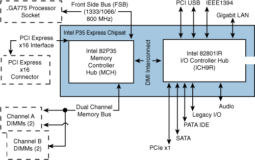
• PCI: The Peripheral Component Interconnect bus was developed in the nineties by Intel as a faster, more compatible alternative to the deprecated ISA bus. It allows for connections to modems and to video, sound, and network adapters; however, PCI connects exclusively to the I/O Controller Hub. Because of this, other high-speed video alternatives were developed that could connect directly to the MCH. The PCI bus is used not only by devices that fit into the PCI slot, but also by devices that take the form of an integrated circuit on the motherboard. The most common PCI cards are rated at 66 MHz, and their corresponding PCI bus is 32-bits wide, allowing for a maximum data transfer rate of 266MB/s. Derivates of PCI include PCI-X, which was designed for servers, using a 64-bit bus and rated for 133 MHz/266 MHz; and Mini-PCI used by laptops. PCI slots are still found on today’s motherboards (as shown in Figure 2.3) but are quickly being overtaken by PCIe technology. A comparison of PCI, AGP, and AMR is shown in Figure 2.4. A comparison of PCI and other expansion busses is shown in Table 2.1 at the end of this list of expansion busses.
Figure 2.3 PCIe x16, PCIe x1, and PCI expansion busses

Figure 2.4 AGP, AMR, and PCI expansion busses

Table 2.1 Comparison of PCI, AGP, and PCIe
• AGP: Accelerated Graphics Port was developed for the use of 3D accelerated video cards and alleviated the disadvantages of PCI for video. Originally designed as a 32-bit 66MHz bus (known as 1x), it had a maximum data transfer rate of 266MB/s. Additional versions were delivered, for example, 2x, with a data rate of 533MB/s, effectively doubling the fastest PCI output. (To do this the 66MHz bus was double-pumped to an effective 133MHz.) Two more versions included 4x (quad-pumped) offering 1GB/s, and 8x with a maximum data rate of 2GB/s. The AGP bus connects directly to the MCH or northbridge, addressing one of the limitations of PCI. Although there is some compatibility between cards, it is important to note that different slots (1x, 4x, and 8x) use different voltages. You should verify that the AGP card is compatible with the stated voltage in the motherboard documentation. An example of an AGP slot is shown in Figure 2.4. AGP has been overshadowed more and more by PCIe over the past 5 years.
• PCIe: Currently the king of expansion busses, PCI Express is the high-speed serial replacement of the older parallel PCI standard. The most powerful PCIe slots with the highest data transfer rates connect directly to the MCH (northbridge); the lesser PCIe slots connect to the ICH (southbridge). This expansion bus sends and receives data within lanes. These lanes are considered full-duplex, meaning they can send and receive data simultaneously. PCIe version 1 has a data rate of 250MB/s per lane, version 2 is 500MB/s, and version 3 is 1GB/s. The amount of lanes a PCIe bus uses is indicated with an x and a number, for example, x1 (pronounced “by one”) or one lane. PCIe video cards are currently x16 (16 lanes) and have taken the place of AGP video cards due to their improved data transfer rate. For example, a Version 2 PCIe x16 video card can transfer 8GB of data per second (500MB × 16 = 8GB), which is far greater than AGP could hope to accomplish. Most other PCIe adapter cards are x1, although you might find some x4 cards as well. Of course, compatibility is key. A x1 card can go in a x1 slot or larger, but a x16 card currently only fits in a x16 slot. Figure 2.3 displays a x16 and x1 slot. Keep in mind that x4 and x16 slots are controlled by the MCH (northbridge), whereas x1 slots are controlled by the ICH, as shown in Figure 2.2. Table 2.1 shows a comparison of PCIe and other expansion busses.
Note
A x32 slot is also defined in the PCIe specification. However, as of the publishing of this book, in general you see no more than x16 version 1 and 2 cards allowing for a maximum data rate of 4GB/s or 8GB/s, respectively.
• AMR and CNR: Intel’s audio/modem riser expansion slot was designed to offer a slot with a small footprint that had the capability to accept sound cards or modems. The idea behind this was to attain Federal Communications Commission (FCC) certification (which is a time-consuming and detailed endeavor) for the adapter card once, instead of having to attain FCC certifications for integrated components on motherboards over and over again with each new motherboard released. This way, the card could be transferred from system to system. The idea was flawed from the start, because adapter cards so quickly progress. This technology, and its successor CNR, are not used in today’s motherboards. Figure 2.4 shows an example of AMR. Quite often, expansion busses are labeled on the motherboard just above the slot, as shown in Figure 2.4.
The Communications and Networking Riser (CNR) was Intel’s adaptation of AMR and was meant for specialized networking, audio, and modem technologies. It was superior to AMR because it could be software- or hardware-controlled but had the same result as AMR and has been obsolete since about 2007.
• PCMCIA: The Personal Computer Memory Card International Association is actually an organization that develops the PC Card technology used in laptops; it is not an expansion bus itself. PC Cards (originally called PCMCIA cards) were first designed for additional storage and later for modems, network cards, combo cards, and hard drives. You have probably seen these credit card-sized devices in the past; however, they are being superseded by another technology known as ExpressCard. More information on PCMCIA, PC Card, and ExpressCard can be found in Chapter 11, “Laptops.”
Note
Maximum data transfer rates are never attained, even in a lab environment. You can expect actual throughput to be substantially lower, but professionals use the maximum data rate as a point of reference and as a way of comparison.
I/O Ports and Front Panel Connectors
Without input and output ports, we really could not correspond with the computer, unless it was through telepathy, and I don’t think that technology has developed yet ![]() . These ports also take care of displaying information, printing it, and communicating with other computers. Figure 2.5 shows some typical ports as found on our motherboard.
. These ports also take care of displaying information, printing it, and communicating with other computers. Figure 2.5 shows some typical ports as found on our motherboard.
Figure 2.5 I/O port cluster on the back panel of the motherboard
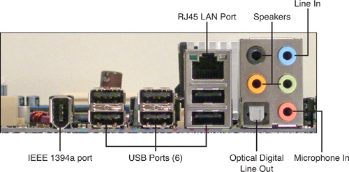
Starting at the left and continuing counter-clockwise, we see the following in the figure:
• IEEE 1394a: Also known as a FireWire or i.Link, this port is used for devices that demand the low-latency transfer of data, usually concerning music or video. This port has a maximum data rate of 400Mbps.
• USB: Universal Serial Bus ports are used by many devices including keyboards, mice, printers, cameras, and much more. The ones shown are USB 2.0 high-speed ports and have a maximum data rate of 480Mbps.
• Audio cluster: There are six ports in this audio cluster including an optical digital output, microphone in, line in, and speaker outs.
• RJ45 LAN port: This is our wired network connection. On this particular motherboard, it is a Gigabit Ethernet LAN controller and is rated for 10/100/1000Mbps.
ExamAlert
Identify back panel connectors (I/O ports) for the exam.
Quite often cases come with front panel ports that might be wired to the motherboard or to an adapter card. These include USB ports, audio ports, memory card readers, external SATA ports, and more.
For more information on I/O ports, see Chapter 12, “Video, Audio, and Peripherals.”
Form Factors
A computer form factor specifies the physical dimensions of some of the components of a computer system. It pertains mainly to the motherboard but also specifies compatibility with the computer case and power supply. The form factor defines the size and layout of components on the motherboard. It also specifies the power outputs from the power supply to the motherboard. The most common form factors, and the ones you need to know for the exam, are ATX, microATX, BTX, and NLX. Let’s discuss these a little further now.
ATX
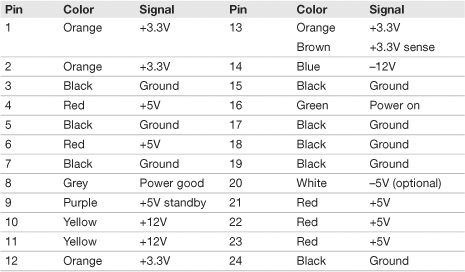
Advanced Technology Extended (ATX) was originally designed by Intel in the mid-nineties to overcome the limitations of the now deprecated AT form factor. It has been the standard ever since. Full-size ATX motherboards measure 12 inches × 9.6 inches (305mm × 244mm). ATX motherboards have an integrated port cluster on the back and normally ship with an I/O plate that snaps into the back of the case, which fills the gaps between ports and keeps airflow to a minimum. One identifying characteristic of ATX is that the RAM slots and expansion bus slots are perpendicular to each other. Generally, ATX has seven expansion slots. For example, our DP35DP motherboard has four PCIe slots and three PCI slots. The ATX specification calls for the power supply to produce +3.3V, +5V, +12V, and −12V outputs and a 5V standby output. The original ATX specification calls for a 20-pin power connector (often referred to as P1), and the newer ATX12V 2.x specification calls for a 24-pin power connector. The additional four pins are rated at +12V, +3.3V, +5V, and ground, as shown in Table 2.2. Those pins are numbered 11, 12, 23, and 24.
Table 2.2 ATX Pin Specification of the Main Power Connector
ExamAlert
Know the voltages supplied to an ATX motherboard by a power supply: +3.3V, +5V, +12V, −12 V outputs, and a +5V standby output.
microATX
microATX (or mATX) was introduced as a smaller version of ATX; these motherboards can be a maximum size of 9.6 inches × 9.6 inches (244 mm × 244 mm) but can be as small as 6.75 inches by 6.75 inches (171.45 mm × 171.45 mm). It is backward compatible with ATX meaning that most microATX boards can be installed within an ATX form factor case, and they use the same power connectors as ATX. Often, they have the same chipsets as ATX as well.
BTX
Balanced Technology Extended (BTX) was designed by Intel in 2004 to combat some of the issues common to ATX. More powerful processors require more power and therefore release more heat. BTX was designed with a more efficient thermal layout. There is a lower profile, and the graphics card is oriented differently than ATX, so heat is generally directed out of the case in a more efficient manner. BTX’s future is uncertain because Intel and AMD processors, and most video cards’ processors, are designed to use less power (and generate less heat). BTX devices are not compatible with ATX devices. One of the ways to identify a BTX motherboard is that the RAM slots and expansion busses are parallel to each other (like the old AT boards). Also, the port cluster is situated differently on a BTX board. In addition, BTX boards are slightly wider than ATX boards; they measure 12.8 inches × 10.5 inches (325mm × 267mm).
NLX
New Low Profile Extended (NLX) utilizes a riser card and a slimline case and was used for inexpensive, mass marketed PCs—the likes of which you are unlikely to see in the field anymore. Dell decided against the use of NLX that could be considered its death blow. NLX was afterward superseded by microATX and others. NLX measures from 8 inches × 10 inches to 9 inches × 13.6 inches. The CompTIA A+ exam objectives list NLX but because it is deprecated, it is doubtful that you will see any questions about this form factor.
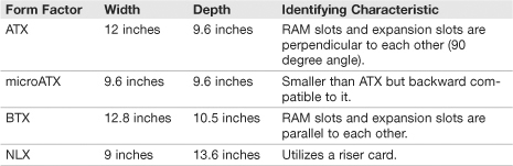
Table 2.3 compares the ATX, microATX, BTX, and NLX form factors supplying the sizes of these motherboards and some of the characteristics that set them apart.
Table 2.3 Comparison of Motherboard Form Factors
ExamAlert
Know the basics of ATX, microATX, BTX, and NLX for the exam.
Cram Quiz
Answer these questions. The answers follow the last question. If you cannot answer these questions correctly, consider reading this section again until you can.
1. What voltage does an orange pin indicate?
![]() A. +12. V
A. +12. V
![]() B. +5. V
B. +5. V
![]() C. -5. V
C. -5. V
![]() D. +3.3. V
D. +3.3. V
2. Which motherboard form factor measure 12 inches × 9.6 inches?
![]() A. microATX
A. microATX
![]() B. BTX
B. BTX
![]() C. ATX
C. ATX
![]() D. CTX
D. CTX
3. Which expansion bus uses lanes to transfer data?
![]() A. PCI
A. PCI
![]() B. PCI-X
B. PCI-X
![]() C. PCIe
C. PCIe
![]() D. PCIa
D. PCIa
4. Which Hub does PCIe connect to?
![]() A. Ethernet hub
A. Ethernet hub
![]() B. I/O Controller Hub
B. I/O Controller Hub
![]() C. UPS hub
C. UPS hub
![]() D. Memory Controller Hub
D. Memory Controller Hub
5. Which of these are serial technologies? Select all that apply.
![]() A. USB
A. USB
![]() B. IEEE 1394
B. IEEE 1394
![]() C. PCIe
C. PCIe
![]() D. PCI
D. PCI
Cram Quiz Answers
1. D. Orange signifies +3.3 volts. Red indicates +5 volts, and yellow is +12 volts; −5 volts would be the white optional wire.
2. C. ATX boards measure 12 inches × 9.6 inches.
3. C. PCIe (PCI Express) uses serial lanes to send and receive data.
4. D. PCIe connects to the Memory Controller Hub (MCH) directly. On AMD-based boards and newer Intel boards, this would be referred to generically as the northbridge.
5. A, B, and C. The only one listed that is not a serial technology is PCI that is a 32-bit parallel technology.
The BIOS
BIOS, CMOS, and the Lithium Battery
The BIOS, CMOS and lithium battery have a nice, little relationship with each other. In a way, the BIOS relies on the CMOS, and the CMOS relies on the lithium battery, as shown in Figure 2.6.
Figure 2.6 The BIOS, CMOS, and lithium battery
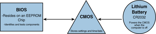
The Basic Input Output System (BIOS) is the first thing that runs when you boot the PC. The BIOS’s job is to identify, test, and initialize components of the system. It then points the way to the operating system so that the OS can load up and take over. Collectively, this process is known as bootstrapping. Originally, the BIOS was stored on a Read-Only Memory (ROM) chip. It later progressed to a Programmable ROM (PROM) enabling the user to modify settings in the BIOS. Finally, today’s system BIOS resides on an EEPROM chip on the motherboard. EEPROM stands for Electrically Erasable Programmable ROM and means that we cannot only modify settings, but also fully update the BIOS by erasing it and rewriting it in a process known as flashing.
The complimentary metal-oxide semiconductor (CMOS) stores the contents of the BIOS’s findings. For example, the type and speed of the processor, capacity of the hard drive, and current time and date. It uses little power that makes it a good choice for storing these settings. When the computer is on, the CMOS chip is powered by the power supply. However, CMOS by nature is volatile, so if is not receiving power, it loses its stored contents.
Lithium battery to the rescue! The lithium battery powers the CMOS when the computer is shut off. The most-common battery used on today’s motherboards is the CR2032, a nickel-sized battery that snaps into the motherboard and has a shelf life of anywhere from 2 years to 10 years depending on usage. The more you leave the computer on, the longer the battery will last. The lithium battery is sometimes referred to simply as the CMOS battery.
The POST
The power-on self-test (POST) is the first step in bootstrapping. The POST is essentially a piece of code that the BIOS runs to find out what type of processor is on the motherboard and verifies the amount of RAM. It also identifies busses on the motherboard, and other devices, and identifies what devices are available for booting.
The BIOS indicates any system problems that the POST finds by either on-screen display codes or beep codes. For example, a displayed 301 Error would most likely be a keyboard issue. Or one beep might indicate a memory error. This all depends on the type of BIOS used. The most common vendors of BIOS are American Megatrends (AMI) and Phoenix Technologies. Your motherboard should come with documentation about any possible BIOS error codes. If not, the documentation can usually be downloaded from the manufacturer’s website; you just need to know the model number of the board. In the case of a proprietary computer (Dell, HP, and such), you need the model number of the computer to download any necessary documentation from its website.
But what happens if the display is blank? Special PCI POST adapter cards are available from companies such as JDR Microdevices that can read the system while it is booting. It usually has a two-digit hexadecimal display. If the display shows 00 or FF after the system finishes booting, everything is probably okay. However any other number would indicate a problem that can be cross-referenced in the accompanying booklet, CD, or online documentation.
Accessing and Configuring the BIOS
Accessing the BIOS must be done before the operating system boots. This can be accomplished by pressing a key on the keyboard. It can be F1, F2, F10, DEL, and so on depending on the manufacturer of and type of system. Usually, the correct key displays on the bottom-left portion of the screen when you first start the computer. If there is only a splash screen, you can press Esc to remove it, and hopefully the BIOS key displays. When you press the appropriate key, the system enters the BIOS Setup Utility, sometimes also referred to as CMOS, or just Setup, and displays a screen, as shown in Figure 2.7.
Figure 2.7 The BIOS Setup Utility

From here we can modify many things, several of which are important for the exam:
• Time and Date: These are normally set on the main screen. By default, operating systems retain their time and date from this, unless they synchronize to a time server.
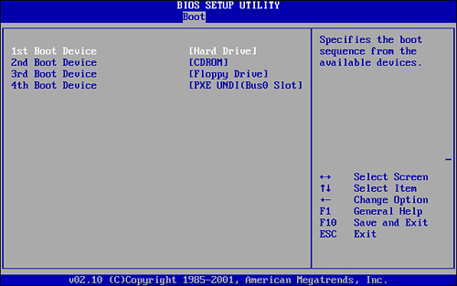
• Boot Device Priority: Also known as BIOS boot order, this setting enables you to select which media will be booted: hard drive, CD-ROM, floppy, USB, and such. This feature can usually be accessed by selecting Boot on the main menu and then selecting Boot Device Priority. For a secure system, it is recommended that you set this to hard drive first, as shown in Figure 2.8.
• Passwords: Two passwords are available on most BIOS: User and Supervisor. The User password (also known as a power-on password) authenticates a user before it enables the operating system to boot. The Supervisor password authenticates a user to the BIOS Setup Utility itself. For a secure system, enter a strong Supervisor password.
• Power Management: This enables you to select if power management is running and which type is used. The older Advanced Power Management (APM) enables the OS to work with the BIOS to achieve power management. This has been supplanted by the Advanced Configuration and Power Interface (ACPI) enabling the OS to take over full control of power management.
• IDE Configuration: This enables you to select and configure the hard drives and optical drives connected to the motherboard. Because most IDE and SATA drives are self-configuring, this setting is used less and less.
You can also enable or disable USB ports and legacy floppy devices and load BIOS defaults if you configure something in the BIOS that stops the system from booting.
Did you ever know someone who forgot his password? To a technician her password is like the back of her hand but maybe not to a user. And for some reason users love to set supervisory passwords in the BIOS—and then forget them. To fix this you need to turn off the computer, disconnect it, open it, and remove the lithium battery. By doing so, the CMOS forgets what it stored. The time and date probably revert to Jan. 1, 2000, or some other date in the past, and all passwords will be erased. In some cases you need to modify the BIOS Configuration Jumper Block solely, or in addition to removing the battery. This is a 3-pin jumper, usually near the lithium battery, that has three possibilities: Normal, Configuration, and Recovery. If necessary, move the jumper shunt from pins 1 and 2 (Normal) to pins 2 and 3 (Configuration); at that point you can access the BIOS without a password. Recovery mode is normally accomplished by removing the jumper altogether. A word to the wise; be ready for improperly labeled motherboards for this jumper configuration block. So you know, motherboards are usually shipped in the Normal state.
Flashing the BIOS
Flashing the BIOS is the term given to the process of erasing the BIOS firmware and rewriting it with a new version of the BIOS. It is sometimes referred to as updating the BIOS. It is important to check for updates to the BIOS, just like you would update an operating system. However, only flash the BIOS if your system needs it; for example, if your motherboard “sees” the processor but doesn’t know specifically what type it is or what speed it runs at. Motherboard manufacturers release these updates quite often, and their description can tell you exactly what they fix. If you build a new computer, you should check for a BIOS update before you even install an operating system. BIOS updates close up security holes, identify new devices or identify them better, and are sometimes released simply to fix some incorrect code. There are several ways to update the BIOS, but generally you would either do it from within Windows or by using some kind of bootable media (floppy, CD-ROM, USB flash drive) to boot the system and rewrite the BIOS. Because the process varies from motherboard to motherboard, I list a few basic steps:
1. Identify what BIOS you are running: To do this, access the BIOS and check the main menu. There is usually be some kind of code that you can check against the latest BIOS download on the manufacturer’s website. If it is the same code, there is no need to update the BIOS. BIOS updates are cumulative, so you need to download and install only the newest version.
2. Download the BIOS from the web: This is usually downloaded in .EXE format. There is normally an instruction file you can download as well, explaining exactly how to flash the BIOS step by step.
3. Select your method of BIOS updating: For example, an Express BIOS Update would be done within Windows; simply download the file and double-click it to begin the process. Or a flash update could be done from a bootable floppy disk or bootable USB device. In this case there is usually a .EXE file that needs to be extracted to the bootable media and a .BAT file that will make the floppy disk bootable. You could also create your own bootable floppy if you have the wherewithal and a lot of time on your hands. With some manufacturers you can download an ISO image to be burned to a CD-ROM. After this is done, boot the computer with the CD and continue to the BIOS update. If a BIOS update were interrupted for some reason or did not complete properly, it might be necessary to recover the BIOS. To do this you need the recovery file and might need to remove the BIOS configuration jumper from the motherboard.
4. Flash the BIOS: Run the BIOS flash update from the appropriate media. If the media is a floppy disk or CD-ROM, restart the computer and boot to that media. Otherwise, run the BIOS update from within Windows. Some BIOS programs are nonresponsive but be careful; they are probably updating the BIOS even though it might look like nothing is happening. Let the system do it’s “thing” for several minutes. Do not run a BIOS update during a lightning storm. Never turn off the computer during a BIOS update, and if you use a laptop, make sure that it is plugged in before starting the update.
ExamAlert
Know how to flash the BIOS for the exam!
Cram Quiz
Answer these questions. The answers follow the last question. If you cannot answer these questions correctly, consider reading this section again until you can.
1. Which component supplies power to the CMOS when the computer is off?
![]() A. Lithium battery
A. Lithium battery
![]() B. POST
B. POST
![]() C. Power supply
C. Power supply
![]() D. BIOS
D. BIOS
2. To implement a secure boot process, which device should be listed first in the Boot Device Priority screen?
![]() A. Floppy drive
A. Floppy drive
![]() B. CD-ROM
B. CD-ROM
![]() C. USB
C. USB
![]() D. Hard drive
D. Hard drive
3. What is the term for how the BIOS readies the computer for and initiates the booting of the operating system?
![]() A. Bootlegging
A. Bootlegging
![]() B. Booting
B. Booting
![]() C. Bootstrapping
C. Bootstrapping
![]() D. POST
D. POST
4. How can we reset a forgotten BIOS supervisory password?
![]() A. Access the BIOS by pressing F2.
A. Access the BIOS by pressing F2.
![]() B. Remove the battery.
B. Remove the battery.
![]() C. Extract the .EXE contents to a floppy.
C. Extract the .EXE contents to a floppy.
![]() D. Remove the P1 connector.
D. Remove the P1 connector.
Cram Quiz Answers
1. A. The lithium battery supplies power to the CMOS when the computer is off. This is because the CMOS is volatile and would otherwise lose the stored settings when the computer is turned off.
2. D. To ensure that other users cannot boot the computer from removable media, set the first device in the Boot Device Priority screen to hard drive.
3. C. Bootstrapping is accomplished by the BIOS. It is defined as one system readying the computer and leading to another larger system.
4. B. Removing the battery (and possibly moving the BIOS configuration jumper) resets the BIOS passwords.
Installing and Troubleshooting Motherboards
Installing Motherboards
You might ask, “Haven’t we talked enough about motherboards?” Not quite. But installing them is easy when you know how, so this section shouldn’t take too long. We’ll break it down into some simple steps:
1. Select a motherboard: If you build a new computer, it should be designed with a compatible case and processor in mind. Also, make sure that it has the expansion ports that you need for audio, video, and so on and verify that it has the I/O ports necessary. Also, give a thought to the applications you will use and if they require or prefer a specific chipset. If you replace a motherboard, make sure that it is compatible with the system you put it in and that all the components can connect to it. If it is a proprietary computer (HP, Dell, and such), you won’t have many choices on motherboards; see the computer manufacturer’s website for details.
2. Employ ESD prevention methods: Use an antistatic strap and mat. And before touching the motherboard, place both hands on an unpainted portion of the case chassis. For more information on ESD preventative measures, see Chapter 16, “Safety and Professionalism.”
3. Ready the case: Most cases come with brass standoffs that are already screwed directly into the case. Additional standoffs usually accompany the motherboard. Line up the motherboard’s predrilled holes with the standoffs and eye it out. Add more standoffs as necessary so that the motherboard is supported properly. Some motherboards come with additional rubber standoffs that provide additional support and protection from ESD.
4. Install the motherboard: Carefully place the motherboard into the case so that the holes meet and line up with the brass standoffs. Secure the motherboard by screwing it in wherever there is a standoff. You might prefer to install the processor and RAM first before installing the motherboard. This has advantages and disadvantages. One advantage is that you wouldn’t have to install them while the motherboard is within the case, decreasing the chances of bending the motherboard. One disadvantage is that the processor and RAM are expensive components that can be easily damaged when installing other components. Of course, in some cases (pun intended), you will have no choice in the matter, but in general, if you worry about damaging the processor and RAM, install them last.
5. Connect cables: Now it’s time to connect the 20-pin P1 or 24-pin P1 power cable from the power supply to the motherboard. This connector is tabbed; make sure that the tabs match up. When connected it should lock into place. Case connectors can be fitted to the motherboard as well. These wires start at the inside front of the case and have thin 2-, 3-, or 4-pin plugs on the other end. They are labeled POWER LED, POWER SW (for power switch), HDD LED, and so on. These are for the power button, reset button, and LED lights. Connect them to the corresponding ports on the edge of the motherboard closest to the front of the case. There might also be front panel ports (USB, audio), external SATA connectors, and more that need to be connected from the case to the motherboard. You can usually find documentation for these additional connections with the case.
6. Install or re-install components: Now it’s time to install the rest of the components such as the hard drives, optical drives, and any other components. Installation of these additional components is covered in their corresponding chapters.
7. Test the installation: Finally, after you install anything, test it! Make sure it works. Boot the computer and access the BIOS. Tool around awhile until you are satisfied that the motherboard is functional. If there is an issue, troubleshoot the problem using the techniques discussed in the next section.
Troubleshooting Motherboards
That time has come. Remember the “big four” mentioned in Chapter 1, “Introduction to Troubleshooting.” The motherboard is one of them. Here’s a common issue: If you boot the computer and don’t get anything on the display, and you are sure that power is not an issue and that the computer is really booting, check all connections. Chances are, it isn’t the motherboard. A loose video card can cause these types of issues; make sure it is firmly pressed into its slot. Check the processor, RAM, and any connectors and other adapter cards in an attempt to rule out the motherboard as the culprit. You see, it is rare that the motherboard fails and checking these connections doesn’t take long; however, removing the motherboard can be time-consuming. If you suspect a particular component has failed, for example the video card, attempt to swap out the video card with a known good device. Do the same with the RAM, even the processor. Finally, if you rule out the rest of the devices, continue troubleshooting the motherboard. Use a POST card if necessary, and if worst comes to worst, swap the motherboard with a known good one.
Let’s run through a quick troubleshooting scenario using the CompTIA six-step troubleshooting methodology outlined in Chapter 1.
Motherboard Issue
In this scenario you are a PC technician working for the PC repair department of an electronics store. You are given a PC that supposedly reverts back to 12:00 AM, January 1, 2000, every time it starts. Troubleshoot!
1. Identify the problem: While viewing the work order, you see some of the customer comments: “PC worked fine until a few days ago. Now, every time it starts, it shows the date as Jan. 1, 2000. After changing the time and date in Windows, it reverts back to Jan 1, 2000, when restarted. Service pack 2 must have messed the computer up; I had updated to service pack 2 and that is when the problem started. Now my Outlook calendar and meetings are not synchronized to my employees Outlook! Please fix right away!”
A co-worker tells you the motherboard should be replaced, and your manager just wants the job done as quickly as possible.
Remember to respect the user/customer, but don’t always take his word for it. Test the computer yourself; you might find something entirely different is causing the problem, and you can save yourself a lot of time. Also, don’t rush, regardless of how fast the manager wants the work done. When you rush, you risk the chance of overlooking the obvious, simple solution.
So, while examining the computer you notice it runs Windows XP Professional and that Windows does indeed revert to Jan 1, 2000, even after you reconfigured the Date and Time Properties window. Otherwise, the computer seems to work fine, aside from Outlook synchronization issues, which is understandable. It doesn’t display anything peculiar or make any strange sounds. And service pack 2 seems to have been installed correctly and is operating properly without any errors in the Event Viewer.
2. Establish a theory of probable cause (question the obvious): Again, we are looking for the obvious or most probable cause. Remembering your training you surmise that the lithium battery in the motherboard has discharged causing the CMOS to lose its contents. If this happens, the BIOS has no recourse but to revert back to its earliest known time, in this case January 1, 2000. It sounds logical, so you move onto the next step.
3. Test the theory to determine the cause: To test this theory, you decide to restart the computer and access the BIOS. When in the BIOS, you change the time to the current time and date, and then you save the settings and shut down the computer. After turning it back on, you access the BIOS again and note that the time has once again reverted back to Jan. 1, 2000. You never accessed Windows in this procedure, so it would seem that the theory is correct. Now, if the time and date you had configured remained in the BIOS without reverting, your theory would probably be incorrect, and you would need to go back to step 2 to formulate a new theory. Although we try to establish and test theories without opening the PC, you can also test the lithium battery with a multimeter. The CR2032 lithium battery has a nominal voltage of 3.0V. If it measures below 2.0 volts, you know the battery has discharged to such a state that it cannot power the CMOS any longer.
4. Establish a plan of action to resolve the problem and implement the solution: Your plan of action should be to replace the CR2032 lithium battery with a new one. Implementing this requires you to shut down the PC and unplug it, open the PC, employ ESD prevention methods, and remove the CR2032 battery. This battery is easy to spot; it is shiny and is about the size of a nickel. They are usually labeled as a CR2032 as well. Removing it entails pushing on a tab and gently prying the battery out. Use something nonmetallic to do this. Then, find or requisition a new lithium battery. Next, test it with your trusty multimeter to make sure it is within proper voltage range (the closer to 3.0 volts the better). Remember that batteries slowly discharge, even when they sit on the shelf. Finally, install the battery into the motherboard.
5. Verify full system functionality and if applicable implement preventative measures: Now you need to make sure it works, so you boot the PC and access the BIOS. From there you update the time and date, save the settings to the BIOS, and shut down the computer. Next, boot the system again, and again access the BIOS. At this point you verify that the time and date have not reverted back to Jan. 1, 2000. If the time is correct, boot to Windows. Check the time in Windows after several “full cycles” (shutting the computer off and turning it back on) and warm boots to ensure that it works properly. As a preventative measure, you might want to recommend that the user synchronize Windows to a time server. This can be done by opening the Date and Time Properties window, selecting the Internet Time tab, and selecting the Automatically synchronize with an Internet time server check box. This way, even if the lithium battery fails, Windows resynchronizes to the time server every time it boots. This also creates a more consistent meeting time for the user and his employees when he sets meetings in Outlook.
6. Document findings, actions and outcomes: Document according to your company’s policies. Complete the work order and any other paperwork necessary. Additional documentation might be required in an application such as Track-it! or another trouble-ticketing software program—and make a mental note of who the person was that said to replace the motherboard; be careful of her suggestions in the future!
Again, it is uncommon to see a motherboard fail, but if it does, it can be because of a few different things. Let’s discuss several of these now.
First and probably the most common of these rarities are BIOS issues. Remember that you might need to flash the BIOS to the latest version. One example is when I built a PC for a friend who picked up an AMD 1.8GHz processor and compatible motherboard. The motherboard specifically stated that it could run 1.0GHz to 1.8GHz processors. But when I booted the system, the BIOS recognized an AMD processor but no specific speed. After running some diagnostic software, I found that the computer was rated at 100MHz processing speed. Not what my friend wanted! However, there were no BIOS updates on the manufacturer’s website concerning this problem. And updating to the latest BIOS did not fix the problem. Emailing the motherboard manufacturer was the only way to fix this issue, which it was not aware of at the time because the AMD processor was so new. After a few days, a new BIOS update was released, and after flashing the system, the BIOS quickly identified the processor as 1.8GHz.
Second are ESD and other electrical issues. These might present themselves intermittently. If you find some intermittent issues, for example the computer reboots out of nowhere, or you receive random Blue Screens of Death, ESD could be the culprit. Or a surge could cause the problem. A particular wire or circuit on the motherboard could have been damaged. Document when failures occur. Swap out the motherboard with a known good one and see if the issue happens again when running through the same processes. If the issue doesn’t recur, chances are the original motherboard is headed for the bit bucket. To give an example of this, let me bring you back in time, 2 years ago, to a customer of mine. In my first visit, I recommended that all computers connect to surge protectors—many were connected directly to AC outlets with no protection. During my second visit, I was presented with a computer (still not surge-protected) that crashed every time a user attempted to log on to the domain. BAM! Blue screen of death. However, he could log on locally with no problems! The Event Viewer in Windows was trying to blame the hardware, and after remembering the bad lightning storms we had the weekend before, I decided to use a POST tester on the motherboard. Sure enough, one of the circuits on the motherboard that led to the integrated network adapter had failed. However, in this case, I changed the I/O and memory address settings for the network adapter, and the problem was fixed. Other computers don’t fare so well, and electrical damage can go right through the power supply to the motherboard, disabling it permanently.
Third are component failures. It is possible that a single component of the motherboard, say the SATA controller, can fail, but the rest of the motherboard works fine. This can also be verified with a POST card tester. To fix this, a separate PCI SATA card can be purchased. Then, you connect the hard drives to the new controller and disable the original SATA controller in the BIOS. Be wary though, sometimes these add-on cards can be pricey—perhaps more pricey than a new motherboard.
And last are manufacturing defects. Printed circuit boards (PCBs) are mass produced at high speed. Defects are uncommon but can occur due to mechanical problems in the machinery or due to engineering error. If you suspect a manufacturing defect, you need to replace the motherboard.
Cram Quiz
Answer these questions. The answers follow the last question. If you cannot answer these questions correctly, consider reading this section again until you can.
1. Before installing a motherboard, what should you do? (Select the best answer.)
![]() A. Install the processor.
A. Install the processor.
![]() B. Verify that it is compatible with the case.
B. Verify that it is compatible with the case.
![]() C. Employ ESD prevention methods.
C. Employ ESD prevention methods.
![]() D. Test the motherboard with a multimeter.
D. Test the motherboard with a multimeter.
2. Which of the following are possible reasons for motherboard failure? (Select all that apply.)
![]() A. Power surge
A. Power surge
![]() B. Manufacturer defect
B. Manufacturer defect
![]() C. CD-ROM failure
C. CD-ROM failure
![]() D. Incorrect USB device
D. Incorrect USB device
3. How can you tell if a lithium battery has been discharged? (Select the best answer.)
![]() A. Use a power supply tester.
A. Use a power supply tester.
![]() B. Check within Windows.
B. Check within Windows.
![]() C. Use a multimeter.
C. Use a multimeter.
![]() D. Plug it into another motherboard.
D. Plug it into another motherboard.
Cram Quiz Answers
1. C. Always employ ESD prevention methods before working with any components inside the computer. Although A and B are correct, they are not the best answers.
2. A and B. Power surges and manufacturing defects are possible reasons for motherboard failure. If a CD-ROM fails, it should not affect the motherboard, and any USB device can connect to a USB port (if it has the right connector). There isn’t really an “incorrect” USB device.
3. C. Although there might be a Windows application that monitors the battery, the surefire way is to test the voltage of the lithium battery with a multimeter.
Additional Reading and Resources
Additional A+ resources: http://www.davidlprowse.com/aplus
Mueller, Scott. Upgrading and Repairing PCs. Que.