
Chapter 16. Networking
This chapter covers a portion of the CompTIA A+ 220-701 objectives 4.1, 4.2, and 4.3, and CompTIA A+ 220-702 objectives 3.1 and 3.2.
A network is a group of computers, peripherals, and software that are connected to each other and can be used together. Special software and hardware are required to make networks work.
Two or more computers connected together in the same office are considered a LAN (local area network). LANs in different cities can be connected to each other by a WAN (wide area network). The Internet represents the world’s largest network, connecting both standalone computers and computers on LAN and WAN networks all over the world.
At one time, it was necessary to use a network operating system (NOS) such as Novell NetWare to enable networking. However, current operating systems, including Windows, include the components needed for networking.
Windows Vista, XP, and Windows 2000 include the following NOS features, enabling systems running these operating systems to be used either as network clients or as peer network servers:
• Client software— Enables systems to connect with other networks. Windows XP/2000 can connect to Windows and Novell NetWare networks, among others, and Windows Vista connects to Windows networks only by default.
• Network protocols— Windows XP/2000 can utilize TCP/IP, IPX/SPX, and NetBEUI. Windows Vista uses TCP/IPv4 and TCP/IPv6 by default.
• File and print sharing— Enables Windows systems to act as peer servers for Windows and Novell NetWare networks.
• Services— Enables specialized network services, such as shared printers, network backup, and more.
“Do I Know This Already?” Quiz
The “Do I Know This Already?” quiz allows you to assess whether you should read this entire chapter or simply jump to the “Exam Preparation Tasks” section for review. If you are in doubt, read the entire chapter. Table 16-1 outlines the major headings in this chapter and the corresponding “Do I Know This Already?” quiz questions. You can find the answers in Appendix A, “Answers to the ‘Do I Know This Already?’ Quizzes and Troubleshooting Scenarios.”
Table 16-1 “Do I Know This Already?” Foundation Topics Section-to-Question Mapping

1. The Windows operating system uses two major types of networks. Which of the following are the two?
a. Client/server
b. Node server
c. Peer-to-peer
d. IP network model
2. One reason for implementing a network is to be able to share the Internet. Which of the following methods can connect a network to the Internet? (Choose all that apply.)
a. Dial-up modem
b. ISDN modem
c. DSL modem
d. Cable modem
3. You are a technician for your company. You have been asked to determine which protocols are in use. You discover that the company is using TCP/IPv4. Which of the following network protocols might you also find on the network? Choose all that apply.
a. TCP/IPv6
b. ISP
c. NetBEUI
d. IEEE
4. Which of the following technologies are part of the TCP/IP suite? (Choose all that apply.)
a. HTTP/HTTPS
b. SSL
c. TLS
d. Ethernet
5. You have been asked to recommend a network topology to use in a new network. Which of the following are valid network topologies?
a. Bus
b. Star
c. Ring
d. Mesh
e. All of these options are correct
6. The company you work for is using the oldest and most commonly used network today, Ethernet. Which of the following is another name for Ethernet?
a. IEEE 1394
b. IEEE 802.11b
c. IEEE 802.3
d. IEEE 802.11g
7. You have been asked by your company to create and install a network. You have decided that you are using Category 5e. What type of cable does Cat5e use? Choose all that apply.
a. STP
b. Coaxial
c. UTP
d. Thin net
8. Which of the following devices would you need if a client asks you to connect his computer to a network? (Choose two.)
a. A network interface card
b. A wireless card
c. AGP adapter card
d. A BNC connector
9. You are installing a network interface card. You have been instructed to configure the network card to be able to send and receive data at the same time. Which of the following settings will you need to configure the network card to complete what has been asked of you?
a. Half duplex
b. Full duplex
c. Super duplex mode
d. Single duplex mode
10. You have been asked by your company to upgrade all hubs to switches. How would this upgrade change the existing network?
a. The network will be slower
b. There is no difference in speeds
c. A switch creates a dedicated full speed connection
d. You do not need to have NIC cards
11. You have been asked by a company to analyze their network. You find several hubs and switches within the network. Which of the following additional devices might you find in this network?
a. Routers
b. Bridges
c. Repeaters
d. VLAN technology
12. You have been contacted by a client that is having problems connecting to the Internet. Where would be a good place to start the troubleshooting process?
a. File and Print Sharing
b. Install NWLink protocol
c. Configure the DHCP server
d. TCP/IP configuration
13. You have been contacted by a client that is unable to access network printers and other shared resources. Which of the following should you verify is installed and enabled?
a. Client services
b. System Monitor
c. File and print sharing
d. TCP/IP protocol
14. What is the name of the service that must be installed on a Windows computer to be able to connect to a network?
a. Client Services for NetWare
b. AppleTalk Protocol
c. Client for Microsoft Networks
d. NDS
15. You need to connect to a server to use shared resources. Which of the following are ways to connect to the server? (Choose two.)
a. Use the UNC path of the resource you need access to
b. Contact the network administrator for help
c. Use the map network drive tool
d. Just walk over to the server and do what you need
16. Which of the following programs allows a user to browse the Internet? (Choose two.)
a. Internet Explorer
b. Firefox
c. Windows Explorer
d. The command prompt
17. A user with your company is having connectivity problems. You need to diagnose the problem as soon as possible. You call the client and walk her through finding the IP address. What should you do next?
a. Run ipconfig /release
b. Run ipconfig /flushdns
c. Ping the IP address of the client’s computer
d. Walk her through how to ping the server
18. A user is unable to access the network. Which of the following could cause this to happen? (Choose all that apply.)
a. Damage to cables
b. A faulty network card
c. The boot files are corrupt
d. Connecting a high speed NIC to a low speed port
Foundation Topics
Network Models
As the network features found in Windows suggest, there are two major network models:
2. Peer-to-peer
It’s important to understand the differences between them as you prepare for the exams and as you work with networks.
Client/Server
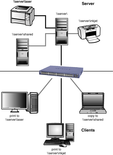
Most departmental and larger networks are client/server networks, such as the one illustrated in Figure 16-1. The networks controlled by Windows Server 2003, Windows 2000 Server, and Novell NetWare servers are examples of client/server networks.
Figure 16-1 A server with three workstations, each of which is using a different shared resource: One is using the server’s inkjet printer, one is printing to the server’s laser printer, and one is copying a file to the server’s RAID array.
![]()
The roles of each computer in a client/server network are distinctive, affecting both the hardware used in each computer and the software installed in each computer. In a client/server environment there are many advantages including centralized administration, better sharing capabilities, scalability, and possibly increased security.
Servers
A server is a computer on the network that provides other computers (called clients or workstations) with access to resources, such as disk drives, folders, printers, modems, scanners, and Internet access. Because these resources can be used by different computers over the network, they are called shared resources.
Servers can also be used for different types of software and tasks. For example, application servers run tasks for clients, file servers store data and program files for clients, and mail servers store and distribute email to clients.
Servers typically have more powerful hardware features than typical PCs, such as SCSI or SATA RAID arrays or network attached storage for hard disk storage, larger amounts of RAM, hot-swap power supplies, and server-optimized network adapters. However, because servers are not operated by an individual user, they often use low-performance integrated or PCI video and might be managed remotely rather than with a keyboard or monitor connected directly to the server.
Clients
A client is a computer that uses the resources on a server. Typical examples of client computers include Windows Vista, XP, and 2000. Depending on the network operating system in use, clients and servers can be separate machines or a client can act as a server and a server can act as a client. Clients can refer to servers either by assigning drive letters to shared folders (see the section “Mapped Drives” later in this chapter) or by using a Universal Naming Convention (UNC) path name to refer to the server, as shown in Figure 16-1. See “The Universal Naming Convention (UNC),” later in this chapter.
Peer-to-Peer
The network features built into Windows allow for peer servers: Computers can share resources with each other, and machines that share resources can also be used as client workstations. As with client/server networking, resources on peer servers can be accessed via universal naming convention (as shown in Figure 16-1) or by mapping drive letters and printer ports on a client to server resources.
As Figure 16-2 shows, if mapped drive letters and printer ports are used in a peer-to-peer network, the same resource will have a different name, depending on whether it’s being accessed from the peer server (acting as a workstation) itself or over the network. In Figure 16-2, the system on the top shares its external hard disk drive with the system on the bottom, which refers to the shared hard disk drive as F:. The system on the bottom shares its printer with the system on the top, which has mapped the shared printer to LPT2.
Figure 16-2 A simple two-station peer-to-peer network, in which each computer acts as a peer server to the other.

The peer server loads file and printer-sharing software to make printers and drives or folders available to others. Because a peer server is also used as a workstation, it is equipped in the same way as a typical workstation or standalone PC.
Internet Connectivity Technologies
One of the best reasons to create a network of any size is to provide access to the Internet. The many types of connectivity technologies that can be used for Internet access are discussed in the following sections.
Tip
As you review the following sections, try to determine which type of Internet connections you use at home and at your workplace.
Modems and Dial-Up Internet Connectivity
Until the late nineties, dial-up networking (DUN) had been the most common way for home and small businesses to connect to the Internet. Dial-up connections are often referred to as analog connections because the device used to make the connection is an analog modem, which connects to the Internet through an ordinary telephone line. Every time you connect to the Internet with a dial-up modem, you are making a network connection.
Modem Technologies and Types
A modem sending data modulates digital computer data into analog data suitable for transmission over telephone lines to the receiving modem, which demodulates the analog data back into computer form. Modems share two characteristics with serial ports:
• Both use serial communication to send and receive information.
• Both often require adjustment of transmission speed and other options.
In fact, most external modems require a serial port to connect them to the computer; some external modems use the USB port instead.
Note
Properly used, the term modem (modulator-demodulator) refers only to a device that connects to the telephone line and performs digital-to-analog or analog-to-digital conversions. However, other types of Internet connections such as satellite, wireless, DSL, and cable Internet also use the term modem, although they work with purely digital data. When used by itself in this book, however, modem refers only to dial-up (telephone) modems.
Modems come in five types: add-on card, external, PC Card, motherboard-integrated, and mini-PCI card. Add-on card modems for desktop computers, such as the one shown in Figure 16-3, fit into a PCI expansion slot. External modems plug into a serial or USB port. PCMCIA (PC Card) modems are sometimes built in a combo design that also incorporates a 10/100 Ethernet network adapter. Many recent desktop computers have integrated modems, as do many notebook computers. However, some notebook computers that appear to have built-in modems actually use modems that use the mini-PCI form factor and can be removed and replaced with another unit. To learn more about expansion slots, see “Expansion Slots” in Chapter 3. To learn more about mini-PCI cards, see “Mini-PCI” in Chapter 9.
Figure 16-3 A typical PCI internal modem. Note the two RJ-11 connectors on the rear of the modem: They enable you to plug a phone into the modem so you can use the modem or your telephone.

Although some high-end add-on card and PC Card modems have a hardware UART (universal asynchronous receiver transmitter) or UART-equivalent chip, most recent models use a programmable digital signal processor (DSP) instead. Modems with a DSP perform similarly to UART-based modems, but can easily be reprogrammed with firmware and driver updates as needed. Low-cost add-on card and PC Card modems often use HSP (host signal processing) instead of a UART or DSP. HSP modems are sometimes referred to as Winmodems or soft modems because Windows and the computer’s processor perform the modulation, slowing down performance. HSP modems might not work with some older versions of Windows or non-Windows operating systems.
External modems, such as the one shown in Figure 16-4, must be connected to a serial or USB port. Serial port versions require an external power source (USB modems are usually powered by the USB port or hub), but the portability and front-panel status lights of either type of external modem make them better for business use in the minds of many users.
Figure 16-4 A typical external modem that connects to a serial port. Note the reset switch, which enables the user to reset the modem without turning off the computer.

![]()
A typical PC Card modem is shown in Figure 16-5. The modem pictured here uses a dongle, a proprietary cable that attaches to one end of the PC Card to enable the modem to plug into a standard telephone jack or telephone line. If the dongle is lost or damaged, the modem can’t be used until the dongle is replaced. Some PC Card modems use an integrated or pop-out RJ-11 jack instead of a dongle (it’s one less thing to lose or break as you travel). To learn more about PC Card modems, see “PCMCIA (PC Card, CardBus),” in Chapter 9.
Figure 16-5 A typical PC Card modem that uses a dongle (right). Many recent PC Card modems feature integrated or pop-out RJ-11 jacks instead of a dongle.

There have been various standards for analog modems used to make dial-up connections. Before the advent of so-called “56K” standards, the fastest dial-up connection possible was 33.6Kbps. Virtually all modems in recent systems or available for purchase support either the ITU v.90 or v.92 standards.
Note
Although v.90 and v.92 modems are all designed to perform downloading at up to 56Kbps, FCC (Federal Communications Commission) regulations limit actual download speed to 53Kbps. Speeds greater than 33.6Kbps apply only to downloads from ISPs (Internet service providers) and their special modems. If you make a direct connection between two PCs, the fastest speed you can have in either direction is just 33.6Kbps (if both modems can run at least that fast).
Analog Modem Installation
The method used for physical installation of the modem varies with the modem type. To install a PCI modem, follow these steps:
Step 1. Take ESD precautions. (See Chapter 17, “Safety and Environmental Issues,” for details.)
Step 2. Open the system and locate an empty slot of the appropriate type.
Step 3. Remove the screw holding the slot cover in place.
Step 4. Remove the slot cover.
Step 5. Install the modem into the slot and fasten it into place with the screw previously used to secure the slot cover.
Step 6. Connect an RJ-11 telephone cable running from the telephone jack in the wall to the line connection.
Step 7. If desired, plug a telephone into the telco jack.
Step 8. Close the system and restart it.
Step 9. Install drivers as required.
Caution
You can drive yourself crazy trying to make a connection with your modem if you plug the RJ-11 telephone cord into the wrong jack. There are actually three ways to make this mistake:
• Plugging the RJ-11 cord into the phone jack instead of the line or telco jack on the modem
• Plugging the RJ-11 cord into the slightly larger RJ-45 jack used for 10/100/1000 Ethernet networking
• Plugging the RJ-11 cord into a HomePNA network card (which also has two RJ-11 jacks) instead of the modem
If you use the HomePNA network, check the network documentation for the correct way to connect your network card and your modem to the telephone line.
To install a PC Card modem, use these steps:
Step 1. Slide the PC Card modem into an empty PC Card slot of the appropriate type (Type II or Type III; see Chapter 9, “Laptop and Portable PCs and Components,” for details).
Step 2. After the operating system indicates the modem has been detected, attach the dongle (if appropriate).
Step 3. If the dongle has an RJ-11 plug, connect it to the telephone wall jack.
Step 4. For modems with a pop-out RJ-11 jack, release the jack.
Step 5. Connect an RJ-11 telephone cable between the RJ-11 connector on the PC Card or dongle and the wall jack.
Step 6. Install drivers as required.
To install an external modem, follow these steps:
Step 1. Connect the modem to a USB or serial port as appropriate.
Step 2. Connect the modem to AC power and turn it on (if necessary).
Step 3. If the modem is not detected automatically, use the operating system’s modem dialog in the Control Panel to detect the modem and install its drivers.
See Chapter 9 for more information about mini-PCI modems.
Dial-Up Internet Service Providers
An Internet service provider (ISP) provides a connection between the user with an analog (dial-up) modem (or other connectivity device) and the Internet. ISPs that provide dial-up access have several modems and dial-up numbers that their customers can access. The ISP’s modems are connected to the Internet via high-speed, high-capacity connections.
An ISP can be selected from many different sources:
• National companies
• Local or regional providers
• Specialized providers such as those that provide filtered, family-friendly access
Choose an ISP based on its rates, its reliability, or special services (such as content filtration or proprietary content) that are appropriate to your needs.
Creating a Dial-Up Connection
Windows Vista creates dial-up networking (DUN) connections within the Network and Sharing Center window. Windows XP and 2000 create DUN connections within the same window that stores other types of network connections:
• Windows XP stores all types of network connections in the Network Connections window.
• Windows 2000 stores all types of network connections in the Network and Dial-Up Connections window.
Note
If an ISP provides customized setup software, the software will usually create an icon for you in the folder used for DUN connections. This icon contains the settings needed to make your connection.
Requirements for a Dial-Up Internet Connection
All ISPs must provide the following information to enable you to connect to the Internet:
• Client software, including the preferred web browser, dial-up information, and TCP/IP configuration information
• Dial-up access telephone numbers
• Modem types supported (33.6Kbps, 56Kbps, v.90, v.92)
• The username and initial password (which should be changed immediately after first login)
Even if the client software provided by the ISP configures the connection for you, you should record the following information in case it is needed to manually configure or reconfigure the connection:
• The dial-up access telephone number— This might be different for different modem speeds. Users with a 56Kbps modem should know both the standard (33.6Kbps) and high-speed access numbers if different numbers are used.
• The username and password— Windows will often save this during the setup of a DUN connection, but it should be recorded in case the system must be reconfigured or replaced.
• The TCP/IP configuration— This is set individually for each dial-up connection through its properties sheet.
To determine this information, right-click the icon for the connection and select Properties.
For more information, see “TCP/IPv4 Configuration” later in this chapter.
ISDN Internet Connectivity
ISDN (Integrated Services Digital Network) was originally developed to provide an all-digital method for connecting multiple telephone and telephony-type devices. such as fax machines, to a single telephone line and to provide a faster connection for teleconferencing for remote computer users. A home/small office-based connection can also provide an all-digital Internet connection at speeds up to 128Kbps. Line quality is a critical factor in determining whether any particular location can use ISDN service. If an all-digital connection cannot be established between the customer’s location and the telephone company’s central switch, ISDN service is not available or a new telephone line must be run (at extra cost to you!).
Note
The telephone network was originally designed to support analog signaling only, which is why an analog (dial-up) modem that sends data to other computers converts digital signals to analog for transmission through the telephone network. The receiving analog modem converts analog data back to digital data.
ISDN Hardware
In order to make an ISDN connection, your PC (and any other devices that share the ISDN connection) needs a device called an ISDN terminal adapter (TA). A TA resembles a conventional analog modem. Internal models plug into the same PCI, ISA, and PC Card slots used by analog modems, and external models use USB or serial ports. External TAs often have two or more RJ-11 ports for telephony devices, an RJ-45 port for the connection to the ISDN line, and a serial or USB port for connection to the computer. For more information about these ports, see Chapter 7.
Setting Up an ISDN Connection
ISDN connections (where available) are provided through the local telephone company. There are two types of ISDN connections:
• Primary Rate Interface (PRI)
• Basic Rate Interface (BRI)
A PRI connection provides 1.536Mbps of bandwidth, whereas a BRI interface provides 64Kbps (single-channel) or 128Kbps (dual-channel) of bandwidth. BRI is sold to small businesses and home offices; PRI is sold to large organizations. Both types of connections enable you to use the Internet and talk or fax data through the phone line at the same time.
A direct individual ISDN connection is configured through the network features of Windows with the same types of settings used for an analog modem connection. Configuring a network-based ISDN connection is done through the network adapter’s TCP/IP properties window. For more information, see “TCP/IPv4 Configuration,” later in this chapter.
Tip
Most telephone companies have largely phased out ISDN in favor of DSL, which is much faster and less expensive.
Broadband Internet Services (DSL, Cable, Satellite)
Broadband Internet service is a blanket term that refers to the following Internet access methods: digital subscriber line (DSL), cable, and satellite. All of these methods provide bandwidth in excess of 300Kbps, and current implementations are two-way services, enabling you to use your telephone while accessing the Internet.
Note
Other types of broadband Internet service, including direct wireless (using microwave transceivers) and powerline, are not part of the A+ Certification exam domains, but you might encounter them in some areas.
Digital Subscriber Line (DSL)
DSL (Digital Subscriber Line), like ISDN, piggybacks on the same telephone line used by your telephone and fax machine, but it differs from ISDN in many ways. Like ISDN, DSL requires a high-quality telephone line that can carry a digital signal, but unlike ISDN, DSL is designed strictly for Internet access.
When it comes to connection speed, DSL leaves BRI ISDN in the dust. There are two major types of DSL: ADSL (Asynchronous DSL) and SDSL (Synchronous DSL). Their features are compared in Table 16-2.
Table 16-2 Common DSL Services Compared

Note
Downstream refers to download speed; upstream refers to upload speed. SDSL gets its name (Synchronous DSL) from providing the same speed in both directions; ADSL is always faster downstream than upstream.
A device known as a DSL modem is used to connect your computer to DSL service. DSL modems connect to your PC through the RJ-45 (Ethernet) port or the USB port. The rear of a typical DSL modem that uses an Ethernet (RJ-45) connection is shown in Figure 16-6
Figure 16-6 The rear of a typical DSL modem with a power port (top left), RJ-45 data port to the PC (top center), and an RJ-11 telephone line port (top right). The RJ-45 cable is shown at bottom left, and the RJ-11 cable is shown at bottom right.
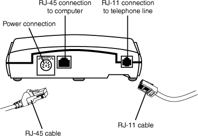
As Figure 16-6 indicates, DSL uses the same telephone lines as ordinary telephone equipment. However, your telephone can interfere with the DSL connection. To prevent this, in some cases a separate DSL line is run from the outside service box to the computer with the DSL modem. However, if your DSL provider supports the self-installation option, small devices called microfilters are installed between telephones, answering machines, fax machines, and other devices on the same circuit with the DSL modem. Microfilters can be built into special wall plates, but are more often external devices that plug into existing phone jacks as shown in Figure 16-7.
Figure 16-7 A typical self-installed DSL setup. The DSL vendor supplies the DSL modem (center) and microfilters that attach between telephones and other devices and the wall outlet (right).

![]()
Some DSL connections are configured as an always-on connection similar to a network connection to the Internet. However, many vendors now configure the DSL connection as a PPPoE (point-to-point protocol over Ethernet) connection instead. A PPPoE connection requires the user to make a connection with a username and password.
Note
Windows Vista and Windows XP have native support through its Network Connection wizard. With older versions of Windows, the vendor must provide setup software.
Cable Internet
Cable Internet service piggybacks on the same coaxial cable that brings cable TV into a home or business. A few early cable ISPs used internal cable modems, which supported one-way traffic. (The cable was used for downloads and a conventional telephone line was used for uploads and page requests.) Virtually all cable Internet service today is two-way and is built upon the fiber-optic network used for digital cable and music services provided by most cable TV vendors.
Cable Internet can reach download speeds anywhere from 1Mbps up to 10Mbps or faster. Upload speeds are typically capped at 128Kbps, but some vendors now offer faster upload speeds in some plans.
Note
You can have cable Internet service without having cable TV.
Some cable TV providers use the same cable that carries cable TV for cable Internet service, while others run a separate cable to the location. When the same cable is used for both cable TV and cable Internet service, a splitter is used to provide connections for cable TV and Internet. The splitter prevents cable TV and cable Internet signals from interfering with each other. One coaxial cable from the splitter goes to the TV or set-top box as usual; the other one goes into a device known as a cable modem. Almost all cable modems are external devices that plug into a computer’s 10/100 Ethernet (RJ-45) or USB port. Figure 16-8 shows a typical cable Internet connection.
Figure 16-8 A typical cable modem and cable TV installation. The cable modem can be connected to the computer through an RJ-45 cable or a USB cable.

![]()
A cable Internet connection can be configured through the standard Network properties sheet in Windows or with customized setup software, depending upon the ISP.
Satellite
Satellite Internet providers, such as HughesNet (previously known as DirecWAY, and, before that, as DirecPC), Starband, and WildBlue use dish antennas similar to satellite TV antennas to receive and transmit signals between geosynchronous satellites and computers. In some cases, you might be able to use a dual-purpose satellite dish to pick up both satellite Internet and satellite TV service.
Note
Geosynchronous satellites orbit the Earth’s equator at a distance of more than 22,000 miles (approximately 35,000 kilometers). Because of their orbit and altitude, they remain in the same location in the sky at all times. In the Northern Hemisphere, you need an unobstructed view of the southern sky to make a connection. In the Southern Hemisphere, you need an unobstructed view of the northern sky to make a connection.
Satellite Internet services use external devices often called satellite modems to connect the computer to the satellite dish. They connect to the USB or Ethernet (RJ-45) port in a fashion similar to that used by DSL or cable modems.
The FCC requires professional installation for satellite Internet service because an incorrectly aligned satellite dish with uplink capabilities could cause a service outage on the satellite it’s aimed at. Setup software supplied by the satellite vendor is used to complete the process.
LANs and Internet Connectivity
A LAN is an ideal way to provide Internet access to two or more users. However, a LAN by itself cannot connect to the Internet. Two additional components must also be used with a LAN to enable it to connect to the Internet:
• An Internet access device— This could be a dial-up modem, but more often a broadband connection such as DSL, cable, or satellite is used.
• A router—This device connects client PCs on the network to the Internet through the Internet access device. To the Internet, only one client is making a connection, but the router internally tracks which PC has made the request and transmits the data for that PC back to that PC, enabling multiple PCs to access the Internet through the network.
Note
As an alternative to a router, some small networks use a gateway, which is a PC configured to share its Internet connection with others on the network. Windows 2000 and later versions support this feature, known as Internet Connection Sharing. Note that wireless access devices known as gateways actually resemble routers.
Network Protocols
The 2009 A+ Certification Exams expect you to understand the major features of these network protocols:
• TCP/IP
Although most current networks are based on TCP/IP, you might encounter others in some networks. The following sections cover the major features of these networks. For information about configuring these protocols, see “Networking Configuration,” later in this chapter.
TCP/IP
TCP/IP is short for Transport Control Protocol/Internet Protocol. It is a multiplatform protocol used for both Internet access and for local area networks. TCP/IP is used by Novell NetWare 5.x and later and Windows Vista/XP/2000 as the standard protocol for LAN use, replacing NetBEUI (used on older Microsoft networks) and IPX/SPX (used on older versions of Novell NetWare). Using TCP/IP as a network’s only protocol makes network configuration easier because users need to configure only one protocol to communicate with other network clients, servers, or with the Internet.
Tip
Most networking you’ll perform in the real world uses TCP/IP. TCP/IP is also the most complex network to configure, especially if you need to use a static IP address. Make sure you understand how it works before you take your exams!
NetBEUI/NetBIOS
NetBEUI (NetBIOS Extended User Interface), the simplest protocol, is an enhanced version of an early network protocol called NetBIOS (NetBIOS itself is no longer used for this purpose). Historically, NetBEUI was used primarily on peer networks using Windows, with direct cable connection between two computers, and by some small networks that use Windows NT Servers. NetBEUI lacks features that enable it to be used on larger networks: It cannot be routed or used to access the Internet.
Note
NetBEUI is not officially supported in Windows XP or Vista, although Microsoft provides the NetBEUI protocol on the XP distribution CD in the ValueaddMSFTNetNetBEUI folder for use with older networks or for troubleshooting. For details on how to install NetBEUI in Windows XP, see the Microsoft Knowledge Base article 301041 available at http://support.microsoft.com/kb/301041. NetBIOS can be used in conjunction with TCP/IP in Windows XP and Vista.
TCP/IP Applications and Technologies
TCP/IP actually is a suite of protocols used on the Internet for routing and transporting information. The following sections discuss some of the application protocols that are part of the TCP/IP suite, as well as some of the services and technologies that relate to TCP/IP.
ISP
An ISP (Internet service provider) provides the connection between an individual PC or network and the Internet. ISPs use routers connected to high-speed, high-bandwidth connections to route Internet traffic from their clients to their destinations.
HTTP/HTTPS
Hypertext Transfer Protocol (HTTP) is the protocol used by web browsers, such as Internet Explorer and Netscape Navigator, to access websites and content. Normal (unsecured) sites use the prefix http:// when accessed in a web browser. Sites that are secured with various encryption schemes are identified with the prefix https://.
Note
Most browsers connecting with a secured site will also display a closed padlock symbol onscreen.
SSL
Secure Socket Layers (SSL) is an encryption technology used by secured (https://) websites. To access a secured website, the web browser must support the same encryption level used by the secured website (normally 128-bit encryption) and the same version(s) of SSL used by the website (normally SSL version 2.0 or 3.0).
TLS
Transport Layer Security (TLS) is the successor to SSL. SSL3 was somewhat of a prototype to TLS, and was not fully standardized. TLS was ratified by the IETF in 1999. However, many people and companies may still refer to it as SSL.
HTML
Hypertext Markup Language (HTML) is the language used by web pages. An HTML page is a specially formatted text page that uses tags (commands contained in angle brackets) to change text appearance, insert links to other pages, display pictures, incorporate scripting languages, and provide other features. Web browsers, such as Microsoft Internet Explorer and Netscape Navigator, are used to view and interpret the contents of web pages, which have typical file extensions such as .HTM, .HTML, .ASP (Active Server pages generated by a database), and others.
You can see the HTML code used to create the web page in a browser by using the View Source or View Page Source menu option provided by your browser. Figure 16-9 compares what you see in a typical web page (top window) with the HTML tags used to set text features and the underlined hyperlink (bottom window). The figure uses different text size and shading to distinguish tags from text, and so do most commercial web-editing programs used to make web pages.
Figure 16-9 A section of an HTML document as seen by a typical browser uses the HTML tags shown in Notepad for paragraphs (<P>) titles (<H4>, </H4>) and hyperlinks (<A HREF>, </A>).

Tags such as <P> are used by themselves, and other tags are used in pairs. For example, <A HREF...> is used to indicate the start of a hyperlink (which will display another page or site in your browser window), and </A> indicates the end of a hyperlink.
Note
The World Wide Web Consortium (http://www.w3c.org) sets the official standards for HTML tags and syntax, but major browser vendors, such as Microsoft and Netscape, often modify or extend official HTML standards with their own tags and syntax.
FTP
File Transfer Protocol (FTP) is a protocol used by both web browsers and specialized FTP programs to access dedicated file transfer servers for file downloads and uploads. When you access an FTP site, the site uses the prefix ftp://.
Windows contains ftp.exe, a command-line FTP program; type FTP, press Enter, and then type ? at the FTP prompt to see the commands you can use.
FTP sites with downloads available to any user support anonymous FTP; if any credentials are required, it’s typically the user’s email address as a password (the username is preset to anonymous). Some FTP sites require the user to log in with a specified username and password.
Tip
Although you can use Windows’ built-in FTP client for file uploads and downloads with both secured and unsecured FTP sites, you should consider using third-party FTP products such as FileZilla (http://filezilla-project.org/) or WS_FTP Pro (http://www.ipswitchft.com/products/ws_ftp_professional/). These programs enable you to create a customized setup for each FTP site you visit, and will store passwords, server types, and other necessary information. They also enable faster downloads than typical web browsers running in ftp:// mode.
Telnet
Telnet enables a user to make a text-based connection to a remote computer or networking device and use it as if he were a regular user sitting in front of it, rather than simply downloading pages and files as he would with an http:// or ftp:// connection.
Windows contains a command-line Telnet program. To open a connection to a remote computer, enter a command such as
telnet a.computer.com
To use other commands, open a command prompt, type telnet, and press the Enter key. To see other commands, type ?/help.
Note
The remote computer must be configured to accept a Telnet login. Typically, TCP port 23 on the remote computer must be open before a login can take place.
SSH
Secure Shell (SSH) allows data to be exchanged between computers on a secured channel. This protocol offers a more secure replacement to FTP and TELNET. The Secure Shell server housing the data you want to access would have port 22 open.
DNS
The domain name system (DNS) is the name for the network of servers on the Internet that translate domain names, such as www.informit.com, and individual host names into their matching IP addresses. If you manually configure an IP address, you typically provide the IP addresses of one or more DNS servers as part of the configuration process.
Caution
Can’t access the site you’re looking for? Got the wrong site? You might have made one of these common mistakes:
• Don’t assume that all domain names end in .com— Other popular domain name extensions include .net, .org, .gov, .us, .cc, and various national domains such as .uk (United Kingdom), .ca (Canada), and many others.
• Don’t forget to use the entire domain name in the browser— Some browsers will add the www. prefix used on most domain names, but others will not. For best results, spell out the complete domain name.
If you want a unique domain name for either a website or email, the ISP that you will use to provide your email or web hosting service often provides a registration wizard you can use to access the domain name registration services provided by various companies such as VeriSign.
A domain name has three major sections, from the end of the name to the start:
• The top-level domain (.com, .org, .net, and so on)
• The name of the site
• The server type; www indicates a web server, ftp indicates an FTP server, mail indicates a mail server, and search indicates a search server
For example, Microsoft.com is located in the .com domain, typically used for commercial companies. Microsoft is the domain name. The Microsoft.com domain has the following servers:
• www.microsoft.com hosts web content, such as product information.
• support.microsoft.com hosts the Microsoft.com support website, where users can search for Knowledge Base (KB) and other support documents.
• ftp.microsoft.com hosts the File Transfer Protocol server of Microsoft.com; this portion of the Microsoft.com domain can be accessed by either a web browser or an FTP client.
Many companies have only WWW servers, or only WWW and FTP servers.
Note
Some small websites use a folder under a domain hosted by an ISP: www.anisp.com/~asmallsite
All email systems provide transfer of text messages, and most have provisions for file attachments, enabling you to send documents, graphics, video clips, and other types of computer data files to receivers for work or play. Email clients are included as part of web browsers, and are also available as limited-feature freely downloadable or more-powerful commercially purchased standalone email clients. Some email clients, such as Microsoft Outlook, are part of application suites (such as Microsoft Office) and also feature productivity and time-management features.
Tip
Users who travel away from corporate networks might prefer to use a web-based email account, such as Hotmail, or use Outlook Web Access to get access to email from any system with a properly configured web browser.
To configure any email client, you need
• The name of the email server for incoming mail
• The name of the email server for outgoing mail
• The username and password for the email user
• The type of email server (POP, IMAP, or HTTP)
Some email clients and servers might require additional configuration options.
To access web-based email, you need
• The website for the email service
• The username and password
SMTP
The simple mail transfer protocol (SMTP) is used to send email from a client system to an email server, which also uses SMTP to relay the message to the receiving email server.
POP
The post office protocol (POP) is the more popular of two leading methods for receiving email (IMAP is the other). In an email system based on POP, email is downloaded from the mail server to folders on a local system. POP is not a suitable email protocol for users who frequently switch between computers, because email might wind up on multiple computers. The POP3 version is the latest current standard. Users that utilize POP3 servers to retrieve email will typically use SMTP to send messages.
Tip
For users who must use POP-based email and use multiple computers, a remote access solution, such as Windows Remote Desktop or a service such as GoToMyPC, is recommended. A remote access solution enables a user to remotely access the system that connects to the POP3 mail server so he or she can download and read email messages, no matter where he or she working.
IMAP
The Internet message access protocol (IMAP) is an email protocol that enables messages to remain on the email server so they can be retrieved from any location. IMAP also supports folders, so users can organize their messages as desired.
To configure an IMAP-based email account, you must select IMAP as the email server type, and specify the name of the server, your user name and password, and whether the server uses SSL.
Ports
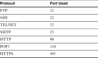
For two computers to communicate they must both use the same protocol. In order for an application to send or receive data it must use a particular protocol designed for that application, and open up a port on the network adapter to make a connection to another computer. For example, let us say you wished to visit www.google.com. You would open up a browser and type http://www.google.com. The protocol being used is HTTP, short for Hypertext Transfer Protocol. That is the protocol that makes the connection to the web server: google.com. The HTTP protocol would select an unused port on your computer (known as an outbound port) to send and receive data to and from google.com. On the other end, google.com’s web server will have a specific port open at all times ready to accept sessions. In most cases the web server’s port is 80, which corresponds to the HTTP protocol. This is known as an inbound port. Table 16-3 displays some common protocols and their corresponding inbound ports.
Table 16-3 Common Protocols and Their Ports
Network Topologies
The physical arrangement of computer, cables, and network devices is referred to as a network topology. There are four different types of network topologies (see Figure 16-10):
• Bus— Computers in a bus topology share a common cable. Connections in this topology are made largely with coaxial 10BASE2 and 10BASE5 cables.
• Star— Computers in a star topology connect to a central hub or switch (wired) or access point (wireless). This topology is used by 10BASE-T (10 Mbps Ethernet), 100BASE-T (Fast Ethernet), and 1000BASE-T (Gigabit Ethernet) Ethernet networks and by Wireless Ethernet (Wi-Fi) when configured for the default infrastructure mode.
• Ring— Computers in a ring topology either connect as a physical ring, for example FDDI networks; or a logical ring, as is the case with Token Ring networks.
• Peer-to-peer (Mesh)—Computers in a peer-to-peer or mesh topology can connect directly to every other computer. This topology is used by computers with multiple network adapters, Wireless Ethernet (Wi-Fi) when configured for peer-to-peer mode, and Bluetooth.
Figure 16-10 Bus, star, ring, and peer-to-peer topologies compared.

The network goes down if a single computer on a bus-topology network fails, but the other network types stay up if one or more computers fail.
Network Types
The A+ Certification Exam expects you to be familiar with the key features of Ethernet and Wireless Ethernet. See the following sections for details.
Wired Ethernet Types
The oldest network in common use today is Ethernet, also known as IEEE-802.3. Most recent wired Ethernet networks use unshielded twisted pair (UTP) cable, but older versions of Ethernet use various types of coaxial cable.
Note
Ethernet uses the Carrier Sense Multiple Access/Collision Detect (CSMA/CD) method of transmission access. Here’s how it works: A station on an Ethernet network can transmit data at any time; if two stations try to transmit at the same time, a collision takes place. Each station waits a random amount of time and then retries the transmission.
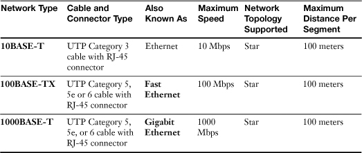
Table 16-4 lists the different types of Ethernet networks and their major features.
Table 16-4 Wired Ethernet Networks
![]()
For more information about cables and connectors, see “Cable and Connector Types,” later in this chapter. For more information about network topologies, see the earlier section “Network Topologies.”
Note
Fiber-optic cables can also be used for Ethernet signaling. They are particularly common for long cable runs with Fast and Gigabit Ethernet.
Wireless Ethernet
Wireless Ethernet, also known as IEEE 802.11, is the collective name for a group of wireless technologies that are compatible with wired Ethernet; these are referred to as wireless LAN (WLAN) standards. Wireless Ethernet is also known as Wi-Fi, after the Wireless Fidelity (Wi-Fi) Alliance (www.wi-fi.org), a trade group that promotes interoperability between different brands of Wireless Ethernet hardware.
Table 16-5 compares different types of Wireless Ethernet to each other.
Table 16-5 Wireless Ethernet Standards

![]()
Note
Wi-Fi certified hardware is 802.11-family Wireless Ethernet hardware that has passed tests established by the Wi-Fi Alliance. Most, but not all, 802.11-family Wireless Ethernet hardware is Wi-Fi certified.
Wireless Ethernet hardware supports both the star (infrastructure) network topology, which uses a wireless access point to transfer data between nodes, and the peer-to-peer topology, in which each node can communicate directly with another node.
Bluetooth
Bluetooth is a short-range low-speed wireless network primarily designed to operate in peer-to-peer mode (known as ad-hoc) between PCs and other devices such as printers, projectors, smart phones, mice, keyboards, and other devices. Bluetooth runs in the same 2.4GHz frequency used by IEEE 802.11b, g, and n wireless networks, but uses a spread-spectrum frequency-hopping signaling method to help minimize interference. Bluetooth devices connect to each other to form a personal area network (PAN).
Some systems and devices include integrated Bluetooth adapters, and others need a Bluetooth module connected to the USB port to enable Bluetooth networking.
Infrared
Infrared is a short-range, low-speed, line-of-sight network method that can be used to connect to other PCs, PDAs, or Internet kiosks. Infrared networking is based on the Infrared Data Association (IrDA) protocol. Some laptops include an integrated IrDA port. IrDA can also be used for printing to printers that include an IrDA port or are connected to an IrDA adapter.
If you want to use a computer that does not have IrDA support with infrared networking, you can add an IrDA adapter. Many desktop motherboards include integrated IrDA support. To enable IrDA support, connect a header cable (available from various third-party sources) to the IrDA port and configure the system BIOS to provide IrDA support. On many systems with integrated IrDA support, one of the COM ports can be switched between its normal mode and IrDA support.
To add IrDA support to computers that don’t include an IrDA port, use a third-party IrDA module that connects to the USB port.
Cellular
Digital cellular phone networks can be used for Internet access and remote networking, a feature that is extremely useful to mobile workers. To enable a laptop to use a cellular network for data access, you need to connect a cellular modem to your PC and purchase the appropriate data access plan from a wireless carrier.
Cellular modems can be connected to USB ports or installed into CardBus or ExpressCard slots. They can be purchased separately or as a bundle with a data access plan. If you purchase a cellular modem separately, make sure it supports the data access method used by your wireless carrier.
VoIP
Voice over IP (VoIP) is an increasingly popular method for providing home and business telephone access. VoIP routes telephone calls over the same TCP/IP network used for LAN and Internet access. Companies such as Vonage, Skype, AT&T, Verizon, and others provide VoIP services.
To add VoIP service to an existing Ethernet network, you can use either an analog telephone adapter (ATA) or a VoIP router. An ATA enables you to adapt standard telephones to work with VoIP services. It plugs into your existing router. A VoIP router can be used as a replacement for an existing wired or wireless router. Typical VoIP routers support most or all of the following features:
• Quality of Service (QoS) support— This feature prioritizes streaming media such as VoIP phone calls and audio or video playback over other types of network traffic.
• One or more FXO ports— An FXO port enables standard analog telephones to be used in VoIP service.
• Real-time Transport Protocol/Real-time Transport Control Protocol (RTP/RTCP)— Supports streaming media, video conferencing, and VoIP applications.
• Session Initiation Protocol (SIP) support— A widely used VoIP signaling protocol also used for multimedia distribution and multimedia conferences.
Cable and Connector Types
There are four major types of network cables:
• Unshielded twisted pair (UTP)
• Shielded twisted pair (STP)
• Fiber-optic
• Coaxial
Network cards are designed to interface with one or more types of network cables, each of which is discussed in the following sections.
Note
Serial (RS-232) null modem and parallel (LPT) crossover cables can be used with direct parallel or direct serial connections (also known as direct cable connection), which are special types of two-station networking included in Windows that use standard network protocols but do not use network cards.
Infrared (IR) ports built into many notebook computers can also be used with direct serial connection.
UTP and STP Cabling
Unshielded twisted pair (UTP) cabling is the most common of the major cabling types. The name refers to its physical construction: four twisted pairs of wire surrounded by a flexible jacket.
UTP cable comes in various grades, of which Category 5e is the most common of the standard cabling grades. Category 5e cabling is suitable for use with both standard 10BaseT and Fast Ethernet networking, and can also be used for Gigabit Ethernet networks if it passes compliance testing.
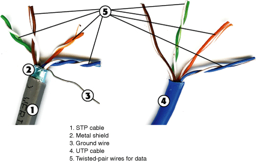
Shielded twisted pair (STP) cabling was originally available only in Category 4, which was used by the now largely outdated IBM Token-Ring Networks. STP uses the same RJ-45 connector as UTP, but includes a metal shield for electrical insulation between the wire pairs and the outer jacket. It’s stiffer and more durable, but also more expensive and harder to loop through tight spaces than UTP. Type 1 STP cable used by older token-ring adapters has a 9-pin connector. STP cabling is also available in Category 5, 5e, and 6 for use with Ethernet networks. It is used where electromagnetic interference (EMI) prevents the use of UTP cable.
Figure 16-11 compares the construction of STP and UTP cables.
Figure 16-11 An STP cable (left) includes a metal shield and ground wire for protection against interference, while a UTP cable (right) does not.
![]()
Table 16-6 lists the various types of UTP and STP cabling in use and what they’re best suited for.
Table 16-6 Categories and Uses for UTP and STP Cabling

![]()
Figure 16-12 compares Ethernet cards using UTP (or STP), thin coaxial, and thick coaxial cables and connectors to each other.
Figure 16-12 Combo UTP/BNC/AUI Ethernet network cards (left and right) compared with a UTP/STP-only Ethernet card (center) and cables.
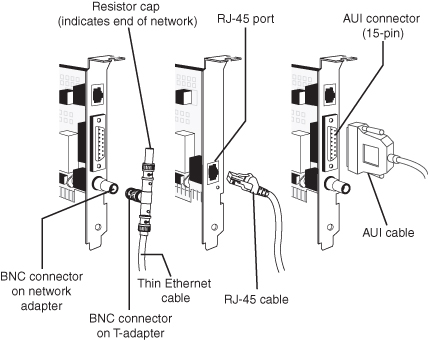
The connector used by Ethernet cards that use UTP or STP cable is commonly known as an RJ45 connector. RJ stands for registered jack; the RJ45 has 8 contacts that accept 8 wires, also known as pins. It resembles a larger version of the RJ11 connector used for telephone cabling. UTP cabling runs between a computer on the network and a hub or switch carrying signals between the two. The hub or switch then sends signals to other computers (servers or workstations) on the network. When a computer is connected to a hub or switch, a straight through cable is used. This means that both ends of the cable are wired the same way. If a computer needs to be connected directly to another computer, a crossover cable, which has a different pin configuration on one end, is used. Keep in mind that between the computer and the hub or switch, there might be other wiring equipment involved, for example RJ45 jacks, patch panels, and so on. UTP and STP cable can be purchased in prebuilt form or as bulk cable with connectors, so you can build the cable to the length you need. Figure 16-13 compares RJ11 and RJ45 connectors.
Figure 16-13 RJ11 connector (left) compared to RJ45 connector (right).

![]()
Note
Although RJ45 is the common name for the UTP Ethernet connector, this is a misnomer, the proper name is 8P8C (8 position, 8 contact). Don’t confuse it with the RJ45S connector, an eight-position connector, used for telephone rather than computer data. An RJ45S jack has a slightly different shape than the connector used for Ethernet, and includes a cutout on one side to prevent unkeyed connectors from being inserted into the jack.
To see drawings of the RJ45S jack and other telephone jacks, see http://www.siemon.com/us/standards/13-24_modular_wiring_reference.asp.
Hubs connect different computers with each other on the network. See “Switches and Hubs,” later in this chapter for more information.
UTP and STP cable can be purchased in prebuilt assemblies or can be built from bulk cable and connectors.
FiberOptic
Fiber-optic cabling transmits signals with light rather than with electrical signals, which makes it immune to electrical interference. It is used primarily as a backbone between networks. Fiber-optic cable comes in two major types:
• Single-mode— Has a thin core (between 8 and 10 microns) designed to carry a single light ray long distances.
• Multi-mode— Has a thicker core (62.5 microns) than single-mode; carries multiple light rays for short distances.
Fiber-optic cabling can be purchased prebuilt, but if you need a custom length, it should be built and installed by experienced cable installers because of the expense and risk of damage. Some network adapters built for servers are designed to use fiber-optic cable. Otherwise, media converters are used to interconnect fiber optic to conventional cables on networks.
Note
When Ethernet is run over fiber-optic cables, the letter F is used in place of T (twisted pair) in the name. For example, 10BASE-F is 10 Mbps Ethernet running on fiber-optic cable, 100BASE-F is 100 Mbps Ethernet running on fiber-optic cable, and so on.
Coaxial
Coaxial cabling is the oldest type of network cabling; its data wires are surrounded by a wire mesh for insulation. Coaxial cables, which resemble cable TV connections, are not popular for network use today because they must be run from one station directly to another rather than to or from a hub/switch.
Coaxial cabling creates a bus topology; each end of the bus must be terminated, and if any part of the bus fails, the entire network fails.
The oldest Ethernet standard, 10BASE5, uses a very thick coaxial cable (RG-8) that is attached to a NIC through a transceiver that uses a so-called “vampire tap” to connect the transceiver to the cable. This type of coaxial cable is also referred to as Thick Ethernet or Thicknet.
Thin Ethernet, also referred to as Thinnet, Cheapernet, or 10BASE2 Ethernet was used for low-cost Ethernet networks before the advent of UTP cable. The coaxial cable used with 10BASE2 is referred to as RG-58. This type of coaxial cable connects to network cards through a T-connector that bayonet-mounts to the rear of the network card using a BNC connector. The arms of the T are used to connect two cables, each running to another computer in the network.
If the workstation is at the end of a network, a terminating resistor is connected to one arm of the T to indicate the end of the network (refer to Figure 16-12). If a resistor is removed, the network fails; if a station on the network fails, the network fails.
Two other types of coaxial cable are common in cable Internet, satellite Internet, and fixed wireless Internet installations:
• RG-59— Used in older cable TV or satellite TV installations; 75-ohm resistance. Also used by the long-obsolete Arcnet LAN standard.
• RG-6— Uses same connectors as RG-59, but has a larger diameter with superior shielding; used in cable TV/Internet, satellite TV/Internet, and fixed wireless Internet/TV service; 75-ohm resistance.
Plenum and PVC
The outer jacket of UTP, STP, and coaxial cable is usually made of PVC (polyvinyl chloride), a low-cost durable vinyl compound. Unfortunately, PVC creates dense poisonous smoke when burned. If you need to run network cable through suspended ceiling or air vents, you should use more-expensive plenum cable, which produces less smoke and a lower level of toxic chemicals when burned.
Connector Types
Most coaxial cables, including RG-58, RG-59, and RG-6 use a BNC (Bayonet Neill-Concelman) connector. RG-58 uses a T-adapter to connect to a 10BASE2 Ethernet adapter. RG-11 (Thicknet) cable is connected to an Ethernet card by means of an external transceiver, which attaches to the AUI port on the rear of older Ethernet network cards. The transceiver attaches to the cable with a so-called “vampire tap.”
10BASE-T, 100BASE-T, and 1000BASE-T Ethernet cards using copper wire all use the RJ45 connector shown in Figure 16-13, as do newer token-ring, some ISDN and most cable Internet devices. DSL devices often use the RJ11 connector shown in Figure 16-13, as do dial-up modems.
To attach a cable using RJ11 or RJ45 connectors to a network card or other device, plug it into the connector so that the plastic locking clip snaps into place; the cable and connector will fit together only one way. To remove the cable, squeeze the locking clip toward the connector and pull the connector out of the jack. Some cables use a snagless connector; squeeze the guard over the locking clip to open the clip to remove the cable.
Fiber-optic devices and cables use one of several connector types. The most common include
• SC— Uses square connectors
• ST— Uses round connectors
• FC— Uses a round connector
See Figure 16-14. If you need to interconnect devices which use two different connector types, use adapter cables which are designed to match the connector types and other characteristics of the cable and device.
Figure 16-14 SC, FC, and ST fiber-optic cable connectors compared.

![]()
Installing Network Interface Cards
Although many recent computers include a 10/100 or 10/100/1000 Ethernet port or a Wireless Ethernet (WLAN) adapter, you often need to install a network interface card (NIC) into a computer you want to add to a network.
PCI and PCI Express
To install a Plug and Play (PnP) network card, follow this procedure:
Step 1. Turn off the computer and remove the case cover.
Step 2. Locate an available expansion slot matching the network card’s design (most use PCI, but some servers and workstations might use PCI-X or PCI Express).
Step 3. Remove the slot cover and insert the card into the slot. Secure the card in the slot.
Step 4. Restart the system and provide the driver disk or CD-ROM when requested by the system.
Step 5. Insert the operating system disc if requested to install network drivers and clients.
Step 6. The IRQ, I/O port address, and memory address required by the card will be assigned automatically.
Step 7. Test for connectivity (check LED lights, use a command such as ping, and so on), then close the computer case.
USB
Although USB network adapters are also PnP devices, you normally need to install the drivers provided with the USB network adapter before you attach the adapter to your computer. After the driver software is installed, the device will be recognized as soon as you plug it into a working USB port.
Note
If you are using a wireless USB adapter, you can improve signal strength by using an extension cable between the adapter and the USB port on the computer. Using an extension cable enables you to move the adapter as needed to pick up a stronger signal.
Most USB network adapters are bus powered. For best results, they should be attached to a USB port built into your computer or to a self-powered hub. Some adapters support USB 2.0, which provides full-speed support for 100BASE-T (Fast Ethernet) signal speeds.
PC Card/CardBus
PC Card network adapters work with both the original 16-bit PC Card slot and the newer 32-bit CardBus slot. However, CardBus cards work only in CardBus slots.
Both PC Card and CardBus cards are detected and installed by built-in support for these adapters in Windows 2000 and newer versions.
Some PC Card and CardBus network adapters often require that a dongle be attached to the card to enable the card to plug into a network port. See Chapter 9, “Laptops and Portable PCs and Components,” for details.
Configuring Network Interface Cards
Although PCI, USB, PC Card, and CardBus network adapters as well as integrated adapters support PnP configuration for hardware resources, you might also need to configure the network adapter for the type of media it uses, for the speed of the connection and, with Wireless Ethernet adapters, the security settings that are used on the wireless network.
Hardware Resources
Typical network interface card hardware resource settings include
• IRQ
• I/O port address range
If the workstation is a diskless workstation, a free upper memory address must also be supplied for the boot ROM on the card. A few older network cards also use upper memory blocks for RAM buffers; check the card’s documentation.
Media Type
Most recent Ethernet cards are designed to use only UTP Category 3 or greater network cabling. However, some older cards were also designed to use 10BASE5 (Thicknet) or 10BASE2 (Thinnet) cabling. Cards that are designed to use two or more different types of cabling are known as combo cards, and during card configuration, you need to select the type of media that will be used with the card. This option is also known as the Transceiver Type option. Depending upon the card’s drivers, you might need to make this setting through the card’s command-line configuration program or the card’s properties sheet in Windows Device Manager.
Note
Some network adapters designed for use with UTP cable can automatically sense when the cable is not connected. Windows XP might display an icon in the system area to indicate when a cable is not connected to a network adapter. To enable notification, open the Network Connections window, right-click the connection, select Properties, and make sure the option Show Icon in Notification Area When Connected is enabled.
Full/Half-Duplex
If the hardware in use on an Ethernet, Fast Ethernet, or Gigabit Ethernet network permits, you can configure the network to run in full-duplex mode. Full-duplex mode enables the adapter to send and receive data at the same time, which doubles network speed over the default half-duplex mode (where the card sends and receives in separate operations). Thus, a 10BASE-T-based network runs at 20 Mbps in full-duplex mode; a 100BASE-T-based network runs at 200 Mbps in full-duplex mode; and a 1000BASE-T-based network runs at 2,000 Mbps in full-duplex mode.
To achieve full-duplex performance on a UTP-based Ethernet network, the network adapters on a network must all support full-duplex mode, be configured to use full-duplex mode with the device’s setup program or properties sheet, and a switch must be used in place of a hub.
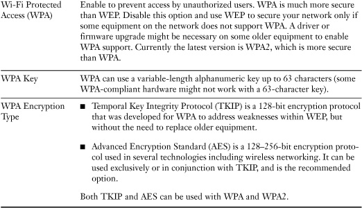
Wireless Ethernet (WLAN) Configuration
Wireless Ethernet requires additional configuration compared to wired Ethernet, as shown in Table 16-7.
Table 16-7 Wireless Ethernet Configuration Settings

![]()
Most home and small-business networks using encryption will use a pre-shared key (PSK). When a pre-shared key is used, both the wireless router or access point and all clients must have the same PSK before they can connect with each other. WPA and WPA2 also support the use of a RADIUS authentication server, which is used on corporate networks.
Switches and Hubs
Hubs connect different computers with each other on an Ethernet network based on UTP or STP cabling. A hub has several connectors for RJ45 cabling, a power source, and signal lights to indicate network activity. Most hubs are stackable, meaning that if you need more ports than the hub contains, you can connect it to another hub to expand its capabilities.
A hub is the slowest connection device on a network because it splits the bandwidth of the connection among all the computers connected to it. For example, a five-port 10/100 Ethernet hub divides the 100 Mbps speed of Fast Ethernet among the five ports, providing only 20 Mbps of bandwidth to each port for Fast Ethernet and 10/100 adapters, and only 2 Mbps per port for 10BASE-T adapters. A hub also broadcasts data to all computers connected to it.
A switch resembles a hub but creates a dedicated full-speed connection between the two computers that are communicating with each other. A five-port 10/100 switch, for example, provides the full 10 Mbps bandwidth to each port connected to a 10BASE-T card and a full 100 Mbps bandwidth to each port connected to a Fast Ethernet or 10/100 card. If the network adapters are configured to run in full-duplex mode and the switch supports full-duplex (most modern switches do), the Fast Ethernet bandwidth on the network is doubled to 200 Mbps, and the 10BASE-T bandwidth is doubled to 20 Mbps. Switches can be daisy-chained in a manner similar to stackable hubs, and there is no limit to the number of switches possible in a network.
Beyond LANs—Repeaters, Bridges, and Routers
Hubs and switches are the only connectivity equipment needed for a workgroup LAN. However, if the network needs to span longer distances than those supported by the network cabling in use or needs to connect to another network, additional connectivity equipment is needed.
• Repeater—A repeater boosts signal strength to enable longer cable runs than those permitted by the “official” cabling limits of Ethernet. Hubs and switches can be used as repeaters.
Note
Windows Vista/XP features built-in bridging capabilities. You can also use a wireless router with a built-in switch to create a single network with both wired and wireless clients.
• Router—A router is used to interconnect a LAN to other networks; the name suggests the device’s similarity to an efficient travel agent, who helps a group reach its destination as quickly as possible. Routers can connect different types of networks and protocols to each other (Ethernet, token ring, TCP/IP, and so on) and are a vital part of the Internet. Router features and prices vary according to the network types and protocols supported.
Networking Configuration
Before a network connection can function, it must be properly configured. The following sections discuss the configurations required for the network protocols covered on the A+ Certification Exams: TCP/IP and NetBEUI.
Installing Network Protocols in Windows
Depending upon the network protocol you want to install and the version of Windows in use on a particular computer, you can install any of several different protocols through the normal Windows network dialogs, as shown in Table 16-8.
Table 16-8 Windows Support for Network Protocols
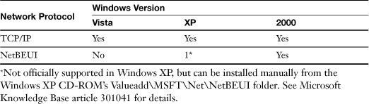
Note
Windows operating systems support TCP/IPv4 and TCP/IPv6. TCP/IPv4 is still the most commonly used version. If TCP/IP is referred to in this book, it generally means TCP/IPv4.
To install a network protocol in Windows Vista or XP/2000, follow this procedure:
Step 1. Open the Network Connections window
• In Windows Vista, click Start, Control Panel, and then double-click the Network and Sharing Center icon. Next, click Manage Network Connections under tasks.
• In Windows XP/2000, click Start, Control Panel, and then double-click the Network Connections (called Network in 2000) icon in Control Panel or right-click My Network Places and select Properties.
Step 2. Right-click the connection you want to modify and select Properties.
Step 3. Click the Install button.
Step 4. Click Protocol.
Step 5. Select the protocol you want to add.
Step 6. Click OK.
After the protocol is installed, select the protocol and click Properties to adjust its properties setting.
TCP/IPv4 Configuration
The TCP/IPv4 protocol, although it was originally used for Internet connectivity, is now the most important network protocol for LAN as well as larger networks. To connect with the rest of a TCP/IP-based network, each computer or other device must have a unique IP address. If the network connects with the Internet, additional settings are required.
There are two ways to configure a computer’s TCP/IP settings:
• Server-assigned IP address
• Static IP address
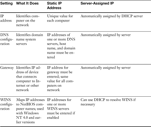
Table 16-9 compares the differences in these configurations.
Table 16-9 Static Versus Server-Assigned IP Addressing
![]()
All versions of Windows default to using a server-assigned IP address. As Table 16-9 makes clear, this is the preferable method for configuring a TCP/IP network. Use a manually assigned IP address if a Dynamic Host Configuration Protocol (DHCP) server (which provides IP addresses automatically) is not available on the network—or if you need to configure a firewall or router to provide different levels of access to some systems and you must specify those systems’ IP addresses.
Note
Routers, wireless gateways, and computers that host an Internet connection shared with Windows’s Internet Connection Sharing or a third-party sharing program all provide DHCP services to other computers on the network.
To configure TCP/IP in Windows, access the Internet Protocol Properties window; this window contains several dialogs used to make changes to TCP/IP. Note that these dialogs are nearly identical in Windows XP and Windows Vista. To open the General tab of the Internet Protocol Properties window, open Network Connections, right-click the network connection, select Properties, click Internet Protocol (TCP/IP) in the list of protocols and features, and click Properties.
TCP/IP Configuration with a DHCP Server
Figure 16-15 shows the General tab as it appears when a DHCP server is used.
Figure 16-15 The General tab is configured to obtain IP and DNS server information automatically when a DHCP server is used on the network.

![]()
Note
To determine the IP address, default gateway, and DNS servers used by a system using DHCP addressing, open a command prompt and enter the ipconfig /all command.
To learn more about using ipconfig, see “Using Ipconfig” in this chapter.
TCP/IP Alternate Configuration
The Alternate Configuration tab shown in Figure 16-16 is used to set up a different configuration for use when a DHCP server is not available or when a different set of user-configured settings are needed, as when a laptop is being used at a secondary location. By default, automatic private IP addressing (APIPA) is used when no DHCP server is in use. APIPA assigns each system a unique IP address in the 169.254.x.x range. APIPA enables a network to perform LAN connections when the DHCP server is not available, but systems using APIPA cannot connect to the Internet.
Figure 16-16 The Alternate Configuration tab is used to set up a different IP configuration for use on another network, or when no DHCP server is available.
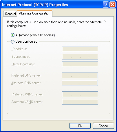
You can also use the Alternate Configuration tab to specify the IP address, subnet mask, default gateway, DNS servers, and WINS servers. This option is useful if this system is moved to another network that uses different IP addresses for these servers.
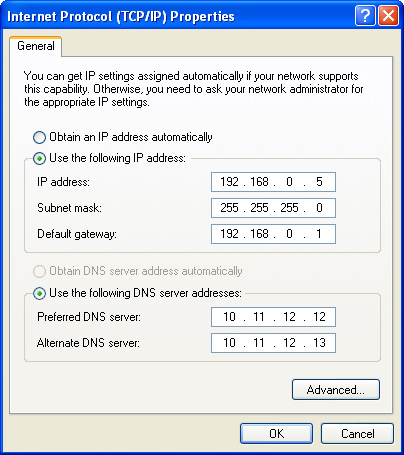
TCP/IP User-Configured IP and DNS Addresses
When a DHCP server is not used, the General tab is used to set up the IP address, subnet mask, default gateway, and DNS servers used by the network client (the information shown in Figure 16-17 is fictitious).
Figure 16-17 The General tab of the TCP/IP properties sheet when manual configuration is used.
![]()
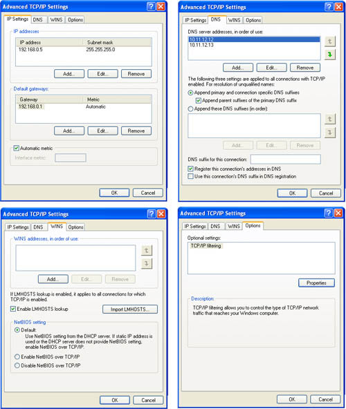
TCP/IP User-Configured Advanced Settings
Click the Advanced button shown in Figure 16-17 to bring up a multitabbed dialog for adding or editing gateways (IP Settings), DNS server addresses (DNS), adjusting WINS resolution (WINS), and adjusting TCP/IP port filtering (Options). These options can be used whether DHCP addressing is enabled or not. Figure 16-18 shows these tabs.
Figure 16-18 The tabs used for Advanced TCP/IP Settings.
Understanding IP Addressing, Subnet Masks, and IP Classes
An IPv4 address consists of a group of four numbers that each range from 0 to 255, for example: 192.168.1.1. IP addresses are divided into two sections: the network portion, which is the number of the network the computer is on, and the host portion, which is the individual number of the computer. Using the IP address we just mentioned as an example, the 192.168.1 portion would typically be the network number, and .1 would be the host number. A subnet mask is used to distinguish between the network portion of the IP address, and the host portion. For example, a typical subnet mask for the IP address we just used would be 255.255.255.0. The 255s correspond to the network portion of the IP address. The 0s correspond to the host portion as shown in Table 16-10.
Table 16-10 An IP Address and Corresponding Subnet Mask

![]()
The subnet mask is also used to define subnetworks, if subnetworking is being implemented. Subnetworking goes beyond the scope of the A+ exam; if you would like more information on subnetworking, refer to CompTIA Network+ N10-004 Exam Prep, Third Edition, by Mike Harwood (Que, July 2009).
Both computers and other networked devices, such as routers and network printers, can have IP addresses, and some devices can have more than one IP address. For example, a router will typically have two IP addresses—one to connect the router to a LAN, and the other that connects it to the Internet, enabling it to route traffic from the LAN to the Internet and back.
IP addresses are divided into three major categories: Class A, Class B, and Class C, which define ranges of IP addresses. Class A is designated for large corporations, ISPs, and government. Class B is designated for mid-sized corporations and ISPs. Class C is designated for small offices and home offices. Each class of IP addresses uses a default subnet mask as shown in Table 16-11.
Table 16-11 Internet Protocol Classification System
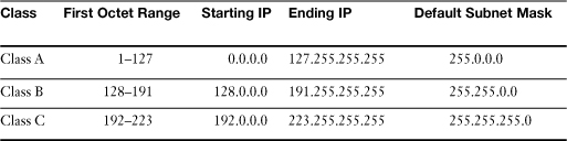
![]()
Note
The 127 network is reserved for testing. This is known as the loopback, for example 127.0.0.1. The usable starting IP for Class A is actually 1.0.0.0.
In any given network the first and last addresses are reserved and cannot be assigned to computers or other hosts. For example, in the 192.168.1.0 network, 192.168.1.1 through 192.168.1.254 can be assigned, but 192.168.1.0 is reserved for the network number, and 192.168.1.255 is reserved for something called the broadcast.
Each number in an IP address is called an octet. An octet is an 8-bit byte. This means that in the binary numbering system the number can range from 00000000—11111111. For example, 255 is actually 11111111 when converted to the binary numbering system. Another example: 192 equals 11000000.
Note
To convert numbers from decimal to binary and vice-versa use the Windows calculator. Press Windows+R to bring up the Run prompt, then type calc. This will run the Windows Calculator. From here click View on the menu bar and select Scientific. Now you will notice radio buttons on the upper left that allow you to change between numbering systems. Simply type any number, and then select the numbering system you want to convert it to.
In a Class A network, the first octet is the network portion of the IP address, and the three remaining octets identify the host portion of the IP address. Class B networks use the first and second octets as the network portion, and the third and fourth octets as the host portion. Class C networks use the first three octets as network portion and the last octet as the host portion of the IP address. Table 16-12 gives one example IP address and subnet mask for each Class.
Table 16-12 Internet Protocol/Subnet Mask Examples for Classes A, B, and C

See a pattern? The size of the network portion increases in octets, and the host portion decreases as you ascend through the classes. As time goes on, you will see more patterns like this within TCP/IP.
WINS Configuration
Windows Internet Naming Service (WINS) matches the NetBIOS name of a particular computer to an IP address on the network; this process is also called resolving or translating the NetBIOS name to an IP address. WINS requires the use of a Window Server that has been set up to provide the resolving service. If WINS is enabled, the IP addresses of the WINS servers must be entered.
If the IP address is provided by a DHCP server, or if a WINS server is used, you will need to enter the correct WINS settings (refer to Figure 16-18).
The network administrator will inform you of the correct settings to use on this dialog.
Gateway
A gateway is a computer or device (such as a router) that provides a connection between a LAN and a wide area network (WAN) or the Internet. Computers that use a LAN connection to connect to the Internet need to enter the IP address or addresses of the gateways on this tab (refer to Figure 16-17) if the computer doesn’t use DHCP to obtain an IP address.
DNS Configuration
The Internet uses the domain name system (DNS) to map domain names, such as www.microsoft.com, to their corresponding IP address or addresses. A computer using the Internet must use at least one DNS server to provide this translation service. Use the DNS Configuration tab to set up the computer’s host name, domain name, and DNS servers (refer to Figure 16-17) if the computer doesn’t use DHCP to obtain an IP address.
Note
Most ISPs and networks have at least two DNS name servers to provide backup in case one fails. Be sure to enter the IP addresses of all DNS servers available to your network. In Windows, these are referred to as preferred and alternate DNS servers.
NetBEUI Configuration
The only configuration required for a NetBEUI network is that each computer has a unique name and that all computers in a particular workgroup use the same workgroup name. To set or change the computer and workgroup names, use the Computer Name tab on the System properties sheet in Windows XP.
Caution
Windows XP also contains a Network Setup wizard, which is designed to automate various parts of the network setup process. Do not use this wizard if you have already configured network settings because the wizard might undo your changes.
Setting Up Shared Resources
Sharing resources with other network users requires the following steps:
Step 1. Installing and/or enabling File and Printer sharing.
Step 2. Selecting which drives, folders, or printers to share.
Step 3. Setting permissions.
Note
Windows XP uses NTFS security permissions only on NTFS-formatted drives and only if simple file sharing is disabled.
The following sections cover performing these processes manually. However, the Network Setup wizard can also perform these steps for you.
Installing File and Printer Sharing
By default, File and Printer Sharing is installed in Windows. However, if you need to add it, File and Printer Sharing can be installed through the network connection’s properties sheet. For Windows Vista/XP/2000, follow this procedure:
Step 1. Open the properties sheet as described in “Installing Network Protocols in Windows,” earlier in this chapter.
Step 2. Click the Install button.
Step 3. Click the Service icon.
Step 4. Click the Add button.
Step 5. Select File and Printer Sharing for Microsoft Networks and click OK.
Step 6. Restart the computer.
Figure 16-19 illustrates a typical Windows XP network properties sheet after File and Printer Sharing is installed. The checkbox indicates this feature is enabled.
Figure 16-19 This network connection has File and Printer Sharing for Microsoft Networks installed and enabled.
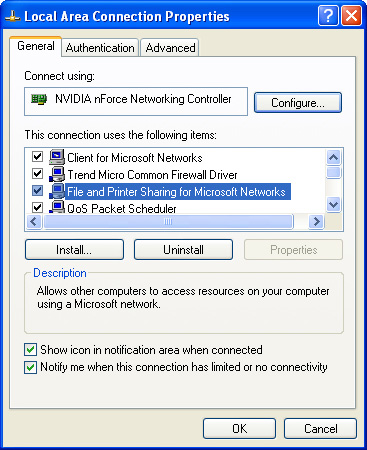
Shared Folders and Drives
A shared folder or drive can be accessed by other computers on the network. Shares can be provided in two ways:
• On a client/server-based network, or a peer-to-peer network with peer servers that support user/group permissions, shares are protected by lists of authorized users or groups. Windows Vista, XP, and 2000 support user/group access control. However, Windows XP supports user/group access control only when the default simple file sharing setting is disabled.
• A peer-to-peer network whose peer servers do not support user/group access control might only offer options for read/only or full access (as with Windows XP using its default simple file sharing setting).
When user/group-based permissions are used, only members who belong to a specific group or are listed separately on the access list for a particular share can access that share. After users log on to the network, they have access to all shares they’ve been authorized to use without the need to provide additional passwords. Access levels include full and read-only and, on NTFS drives, other access levels, such as write, create, and delete.
Sharing a Folder Using Simple File Sharing
To share a folder or drive in Windows XP with simple file sharing enabled, follow these steps:
Step 1. Right-click the folder or drive and select Sharing and Security.
Step 2. If you right-click a drive, Windows XP displays a warning. Click the link to continue.
Step 3. Click the box Share This Folder on the Network to share the folder in read-only mode. To share the folder in read/write mode, click the box Allow Network Users to Change My Files. Click OK.
Figure 16-20 illustrates sharing a folder or drive when simple file sharing is enabled.
Figure 16-20 Setting up a network share in Windows XP using the default simple file-sharing option.
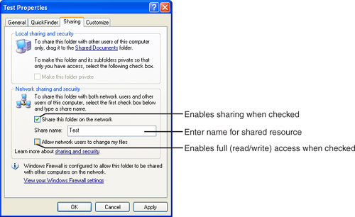
![]()
Sharing a Folder with User/Group Permissions in Windows XP
If you want to set up user/group permissions on Windows XP, you must first disable simple file sharing.
Step 1. Open My Computer or Windows Explorer.
Step 2. Open the Tools menu and click Folder Options.
Step 3. Click the View tab.
Step 4. In the Advanced Settings portion of the dialog, scroll down to Use Simple File Sharing (Recommended) and clear the checkbox.
Step 5. Click Apply and then OK.
After simple file sharing is disabled, you can share a folder and control access with user/group permissions on any drive that uses the NTFS file system.
After simple file sharing is disabled, use this procedure to share a folder or drive:
Step 1. Right-click the folder or drive and select Properties.
Step 2. Click the Sharing tab (see Figure 16-21)
Figure 16-21 Setting up a network share in Windows XP when simple file sharing is disabled.
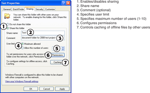
![]()
Step 3. Click Share This Folder and specify a share name. (The default share name is the name of the drive or folder.) Add a comment if desired.
Step 4. Specify the number of users or use the default (10).
Step 5. Click Permissions to set folder permissions by user or group.
Step 6. Click Caching to specify whether files will be cached on other computers’ drives and how they will be cached.
Note
If you need to convert a drive from a FAT-based file system to NTFS, you can use the command-line convert program. For example, if you were to convert the C: drive, the syntax would be
convert c: /FS:NTFS
See “Operating System Access Control” in Chapter 10, “Security,” for details.
Sharing a Folder with User/Group Permissions in Windows Vista
To share a folder in Windows Vista, follow these steps:
Step 1. Ensure that file sharing is enabled. This is done by navigating to Start, Control Panel, and double-clicking the Network and Sharing Center icon. From here, click the down arrow next to File Sharing and select the Turn on File Sharing radio button. (This window is also where you would enable printer sharing.)
Step 2. Click Start, then click Computer.
Step 3. In the Computer window, navigate to a folder that you want to share.
Step 4. Right-click the folder that you want to share, then click Share. The File Sharing window is now displayed.
Step 5. If you have enabled password-protected sharing, use the File Sharing window and select which users will have access to the shared folder and select their permission levels. To allow all users, select the Everyone group within the list of users. If you disabled password-protected sharing, use the File Sharing window and select the Guest or Everyone account. This is the equivalent of simple file sharing in Windows XP.
Step 6. When you are done configuring permissions, click Share and then click Done.
Shared Printers
To set up a printer as a shared printer, follow these steps:
Step 1. Open the Printers or Printers and Faxes folder.
Step 2. Right-click a printer and select Sharing.
Step 3. Select Share This Printer and specify a share name. (In Windows Vista you will have to click click the Sharing tab first.)
Step 4. Click Additional Drivers to select additional drivers to install for other operating systems that will use the printer on the network. Supply driver disks or CDs when prompted.
Administrative Shares
Administrative shares are hidden shares that can be identified by a $ on the end of the share name. These shares cannot be seen by standard users when browsing to the computer over the network; they are meant for administrative use. All the shared folders including administrative shares can be found by navigating to Computer Management > System Tools > Shared Folders > Shares. Note that every volume within the hard drive (C: or D: for example) has an administrative share (for example, C$ is the administrative share for the C: drive). Although it is possible to remove these by editing the Registry, it is not recommended because it might cause other networking issues. You should be aware that only administrators should have access to these shares.
Setting Up the Network Client
The client in both peer-to-peer networks and dedicated server networks is a computer that uses shared resources. To access shared resources, a client computer needs
• Network client software
• The name of the network and server(s) with shared resources
• The printer drivers for the network printers
To install network client software in Windows, open the Properties sheet of the appropriate network connection. To change the name of the network that the computer is a member of, open the System Properties window and click the Computer Name tab.
In Windows XP and 2000 My Network Places is used to locate shared resources and to provide passwords, in Windows Vista it is simply called “Network.” “Printers” is used to set up access to a network printer in all versions of Windows. My Network Places, Network, and Printers can be accessed from the Start Menu or from within Windows Explorer.
Installing Network Client Software
Windows Vista, XP, and 2000 incorporate network client software for Microsoft Networks.
If you need to install additional network clients, such as for NetWare, in Windows XP/2000, follow this procedure:
Step 1. Open the Network Connections (Network in Windows 2000) icon in Control Panel or right-click My Network Places and select Properties.
Step 2. Right-click the connection you want to modify and select Properties.
Step 3. Click the Install button.
Step 4. Click the Client icon.
Step 5. Select the client you want to add.
Step 6. Click OK.
Note
Windows Vista does not support Novell NetWare by default.
Installing a Network Printer
Follow this procedure to install a network printer:
Step 1. Open the Printers and Faxes (or Printers) folder.
Step 2. Click Add a Printer (or Add Printer). In some cases you may need to alternate click anywhere in the white area and select Add Printer.
Step 3. Click Next (Windows XP/2000); then select Network Printer. In Windows Vista, simply click the button to add a network printer. It will try to search for a printer automatically. To bypass this click The Printer I Want Isn’t Listed.
Step 4. You can browse for the printer on a workgroup network, use Active Directory to search for a printer on a domain-based network or enter its name (\serverprintername). You can also specify the printer’s URL. Click Next.
Step 5. After the printer is selected, specify whether you want to use the new printer as the default printer. Click Next.
Step 6. Specify if you want to print a test page. Printing a test page will allow you to verify if the correct print driver has been installed.
Step 7. Click Finish to complete the setup process. Provide the Windows CD or printer setup disk if required to complete the process.
Using Shared Resources
With any type of network, the user must log on with a correct username and password to use any network resources. With a dedicated server, such as Novell or Windows 2000/Server 2003, a single username and password is needed for any network resource the user has permission to use. On a peer-to-peer network using user/group permissions, you must configure each peer server with a list of users or groups. In either case, you must then specify the access rights for each shared folder.
Information can be copied from a shared drive or folder if the user has read-only access; to add, change, or delete information on the shared drive or folder, the user needs full access.
Network printing is performed the same way as local printing after the network printer driver software has been set up on the workstation.
You can identify shared resources with Windows by using Explorer or My Computer. On a Windows XP or 2000 system that is sharing resources with other users, a shared drive, folder, or printer will use a modified icon with a hand, indicating that it is being shared (see Figure 16-22). In Windows Vista, there will be a small icon of two users indicating a share.
Figure 16-22 Viewing a shared folder and shared printers in Windows XP.

To use a shared resource on a peer server that uses share-level security, the user must provide the correct password for any password-protected share. To use a shared resource on a network that uses user/group permissions, the user must log on to the network. The administrator of the server or network has already assigned access levels and permissions to each user or group, so the user can immediately begin using shared resources as permitted.
Shared drives and folders can be referred to by a Universal Naming Convention (UNC) name, a fully qualified domain name (FQDN), or a mapped drive letter Each of these is explained in the following sections.
The Universal Naming Convention (UNC)
The Universal Naming Convention (UNC) is designed to enable users to access network resources such as folders or printers without mapping drive letters to network drives or specifying the type of device that stores the file or hosts the printer. A UNC name has the following structure in Windows:
\servernameshare namepathfilename
A typical UNC path to a document would resemble
\Tiger1ONetDocuments his_doc.doc
A typical UNC path to a shared printer on the same system would resemble
\Tiger1Printername
What does this mean in plain English?
• \Tiger1 is the server.
• O is the share name.
• NetDocuments is the path.
• his_doc.doc is the document.
• Printername is the printer.
UNC enables files and printers to be accessed by the user with 32-bit Windows applications. Because only 23 drive letters (maximum) can be mapped, UNC enables network resources beyond the D–Z limits to still be accessed.
To display the UNC path to a shared folder with Windows XP, right-click the share in My Network Places (Network in Windows Vista) and select Properties. The Target field in the dialog lists the UNC path.
Some Windows applications will display the UNC path to a file even if the file was accessed through a mapped drive letter, and other Windows applications will refer to the UNC path or mapped drive letter path to the file, depending on how the file was retrieved.
Fully Qualified Domain Names (FQDNs)
TCP/IP networks that contain DNS servers often use FQDNs to refer to servers along with, or in place of, UNC names. The structure of an FQDN is
Name-of-server.name-of-domain.root-domain
For example, a server called “charley” in the informit.com domain would have an FQDN of
charley.informit.com
If you want to access the shared Docs folder on charley.informit.com, you would refer to it as
\charley.informit.comDocs
You can also use the IP address of the server in place of the servername. If 192.10.8.22 is the IP address of charley.informit.com, you can access the Docs folder with the following statement:
\192.10.8.22Docs
You can use either UNCs or FQDN along with the Net command-line utility to view or map drive letters to shared folders.
Mapped Drives
Windows enables shared folders and shared drives to be mapped to drive letters on clients. In Windows Explorer and My Computer (Computer in Windows Vista), these mapped drive letters will show up in the list along with the local drive letters. A shared resource can be accessed either through Network/My Network Places/Network Neighborhood (using the share name) or through a mapped drive letter.
Drive mapping has the following benefits:
• A shared folder mapped as a drive can be referred to by the drive name instead of a long Universal Naming Convention path (see “The Universal Naming Convention [UNC]” earlier in this chapter for details).
• If you still use MS-DOS programs, keep in mind that mapped drives are the only way for those programs to access shared folders.
To map a shared folder to a drive in Windows Vista/XP, follow this procedure:
Step 1. Click the shared folder in Network (Vista) or My Network Places (XP).
Step 2. Click Tools, Map Network Drive. (Note: In Windows Vista, the menu bar might be hidden. To show it use the Alt+T shortcut. Alternatively you can right-click the shared resource and select Map Network Drive.)
Step 3. Select a drive letter from the list of available drive letters; only drive letters not used by local drives are listed. Drive letters already in use for other shared folders display the UNC name of the shared folder.
Step 4. Click the Reconnect at Login box if you want to use the mapped drive every time you connect to the network. This option should be used only if the server will be available at all times; otherwise, the client will receive error messages when it tries to access the shared resource. See Figure 16-23.
Figure 16-23 The Map Network Drive dialog can be used to create a temporary or permanent drive mapping.

![]()
Step 5. Click Finish.
Shared folders can be accessed by either their mapped drive letters or by their folder names in Windows Explorer.
Browser Installation and Configuration
A web browser, such as Microsoft Internet Explorer or Mozilla Firefox, is the main interface through which you navigate the Internet. Internet Explorer is a standard component of Windows. Updates and newer versions can be downloaded manually from the Microsoft website or via Windows Update. Other browsers can be downloaded in compressed form and installed manually.
Depending on how you connect with the Internet, you might need to adjust the browser configuration.
Typical options you might need to change include
• Proxies for use with LAN-based or filtered access— Users who access the Internet through a local area network might be doing so through a proxy server. A proxy server receives a copy of the website or content the user wants to look at and checks it for viruses or unapproved content before passing it on. The proxy server information is set through the browser’s configuration menu (for example, Internet Options in Internet Explorer).
• Automatic dial up for convenience— Internet Explorer and most other browsers can also be set to dial up the Internet automatically whenever you start the browser to make Internet access easier. This option is very useful for dial-up connections.
• Email configuration— Most browsers include an email client; the settings for the email server and other options must be made to allow email to be seen and replied to within the browser.
• Disable graphics— Users with extremely slow connections who view primarily text-based pages can disable graphics for extra speed.
• Security settings for Java— Advanced features, such as Java and ActiveX, make sites more interactive, but might also pose a security risk; these features can be limited or disabled through the Security menu.
You can also adjust default colors and fonts and the default start page.
Generally, you should use all the features possible of the browser unless you have speed or security concerns that lead you to disable some features.
Setting Up Your Browser to Use Your Internet Connection
In most cases, users will want the Internet to be available as soon as they open their web browser. Because some users have dial-up connections and some networks use proxy servers to provide firewall protection or content filtering, you might need to adjust the browser configuration to permit Internet access.
To view or adjust the browser configuration for Internet Explorer, follow this procedure:
Step 1. Open Internet Explorer.
Step 2. Click Tools, Internet Options.
Step 3. Click the Connections tab.
Step 4. If the Internet connection uses a dial-up modem, select the correct dial-up connection from those listed and choose Always Dial (to start the connection when the browser is opened) or Dial Whenever a Network Connection Is Not Present. Click Set Default to make the selected connection the default.
Step 5. If the Internet connection uses a network, click Never Dial a Connection, and click LAN Settings to check network configuration.
Step 6. Ask the network administrator if you should use Automatically Detect Settings or whether you should specify a particular automatic configuration script.
Step 7. Click OK to save changes at each menu level until you return to the browser display.
If a proxy server is used for Internet access, it must be specified by servername and port number (refer to Figure 16-24):
Step 1. From the Connections tab, click LAN settings.
Step 2. From the Local Area Network (LAN) Settings window, you have two options underneath Proxy Server. If a single proxy server address and port number is used for all types of traffic, click the Use a Proxy Server checkbox and enter the address and port number. However, if different proxy servers or ports will be used, click the Use a Proxy Server checkbox and click the Advanced button.
Step 3. Specify the correct server and port number to use.
Step 4. Click OK to save changes at each menu level until you return to the browser display.
Figure 16-24 Configuring proxy server settings in Internet Explorer 6.
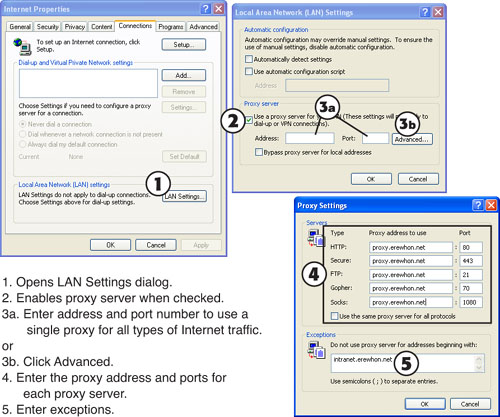
![]()
Enabling/Disabling Script Settings
Some networks use a separate configuration or logon script for Internet access. To specify a script with Internet Explorer, click Tools, Internet Options, Connections, LAN Settings, Use Automatic Configuration Script. Enter the URL or filename of the script and click OK.
Tip
You can also configure Internet Explorer to automatically detect the settings if your network is configured to provide them. However, if you enable this option and the network is not configured to provide them, Internet Explorer will not be able to connect to the Internet.
Configuring Browser Security Settings
You can configure Internet Explorer’s default security settings for Java, ActiveX, and other potentially harmful content through the Internet Options’ Security tab. Open the Internet Options tab with Control Panel, or click Tools, Settings, Internet Options within Internet Explorer.
Depending on the version of Internet Explorer there will be five or four default security settings: High, Medium-high, Medium, Medium-Low, and Low. High blocks almost all active content and prevents websites from setting cookies (small text files that can track website usage). Medium (the default) enables some active content but blocks unsigned ActiveX controls. Medium-low blocks unsafe content but downloads other content without prompts, and low has no safeguards.
Each setting is matched to a web content zone. By default, all sites not in other zones are placed in the Internet zone, which uses Medium-high security (Medium on older versions of Internet Explorer). The local Intranet zone uses Medium-low security by default (medium in older versions). Trusted sites use Medium security by default (Low in older versions); restricted sites use High security by default.
To add or remove sites on the local Intranet, Trusted, or Restricted site list, select the zone and click Sites.
By default, local Intranet sites include all local sites, all sites that don’t use a proxy server, and all UNC network paths. Remove check marks to restrict these options. Click Advanced to add or remove a specific site or to require a secured server. Trusted or Restricted sites display the Add/Remove dialog box immediately.
Note
Click Custom from the main Security tab to adjust the default settings for any security level. If the settings of any zone are misconfigured, one can return to default settings for an individual zone or reset security of all zones by clicking the Reset All Zones to Default Level button.
Using Network Command-Line Tools
Windows contains several command-line tools for troubleshooting and configuring the network. These include the following:
• Net— Displays and uses network resources
• Ping— Tests TCP/IP and Internet connections
• Tracert— Traces the route between a specified website or IP address and your PC
• NSLookup— Displays detailed information about DNS
• IPConfig— Displays detailed TCP/IP configuration about your Windows NT/2000/XP system
The following sections describe these tools.
Using the Net Command
Windows includes the Net command for use in displaying and using network resources from the command line. Some of the Net commands you can use include
• Net Help—Displays help for a Net option; for example, use Net Help View for help with the Net View command.
• Net Use—Maps a network drive to a shared resource on the network; for example, Net Use Q: \Tiger1shared. In this example, Q: will behave just like any other drive letter such as C:, D:, and so on. The only difference is that it will redirect to another computer on the network.
• Net View—Displays other hosts on the network.
• Net Helpmsg errorcode#—Displays the meaning of any Microsoft error code.
To display a complete list of Net commands, type Net /? |More from the command prompt.
Using Ping
Windows can use the Ping command to test TCP/IP, check for connectivity to other hosts on the network, and check the Internet connection for proper operation. Ping is a more reliable way to check an Internet connection than opening your browser, because a misconfigured browser could cause you to think that your TCP/IP configuration is incorrect.
To use Ping to check connectivity with another host on the network, follow this procedure:
Step 1. Open a command-prompt window.
Step 2. Type Ping IPaddress or Ping servername in order to ping another host on the network, then press Enter. For example, to ping a router, typical syntax would be Ping 192.168.1.1.
To use Ping to check your Internet connection, follow this procedure:
Step 1. Start your Internet connection. If you use a LAN to connect to the Internet, you might have an always-on connection.
Step 2. Open a command-prompt window.
Step 3. Type Ping IPaddress or Ping servername and press Enter. For example, to ping a web server called www.erewhon.net, type Ping www.erewhon.net.
By default, Ping sends four data packets from your computer to any IP address or servername you specify. If your TCP/IP connection is working properly, you should see a reply from each ping you sent out indicating how quickly the signals traveled back from the target and the IP address or URL of the target. The replies indicate that the host is alive. Any other message would indicate a problem, for example the “Request timed out” or “Destination host unreachable” messages would require further troubleshooting. Keep in mind that if it’s the local computer that is configured incorrectly, you might not be able to “ping” anything! Also watch for the amount of time the ping took to reply back. A longer latency time could indicate network congestion. Conversely, the lower the time in milliseconds (ms), the faster your connection. Connection speeds vary a great deal due to various factors, such as Internet network congestion, server speed, and the number of relays needed to transfer your request from your computer to the specified server. To check relay information, use the Tracert command.
Using Tracert
The Tracert command is used by Windows to trace the route taken by data traveling from your computer to an IP address or website you specify. By default, Tracert will check up to 30 hops between your computer and the specified website or IP address. To use Tracert to check the routing, follow this procedure:
Step 1. Start your Internet connection. If you use a LAN to connect to the Internet, you might have an always-on connection.
Step 2. Open a command-prompt window.
Step 3. Type Tracert IP address or Tracert servername and press Enter. For example, to trace the route to a Web server called www.erewhon.tv, type Tracert www.erewhon.tv. Tracert displays the IP addresses and URLs of each server used to relay the information to the specified location, as well as the time required.
To see help for the Tracert command, type Tracert without any options and press the Enter key.
Using NSLookup
NSLookup is a command-line tool used to determine information about the DNS. When NSLookup is run without options, it displays the name and IP address of the default DNS server before displaying a DNS prompt. Enter the name of a website or server to determine its IP address; enter the IP address of a website or server to determine its name. Enter a question mark (?) at the prompt to see more options; type exit, and then press Enter to exit the program.
Using Ipconfig
The IPConfig command-line utility is used to display the computer’s current IP address, subnet mask, and default gateway (see Figure 16-25). Ipconfig combined with the /all switch will show more information including the DNS server address and MAC address, which is the hexadecimal address that is burned into the ROM of the network adapter.
Figure 16-25 IPConfig /all displays complete information about your TCP/IP configuration.
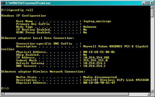
Tip
If you’re having problems seeing other computers on the network or connecting to the Internet on a network that uses server-assigned IP addresses, type IPConfig /release and press Enter; and then type IPConfig /renew and press Enter to obtain a new IP address from the DHCP server on your network.
Network and Internet Troubleshooting
Use this section to prepare for troubleshooting questions involving network hardware and software on the A+ Certification Exams and in your day-to-day work as a computer technician.
Can’t Access Network Resources
If an error message such as Duplicate Computer Name or Duplicate IP Address is displayed during system startup, open the Network icon and change the name of the computer or the system’s IP address. Contact the network administrator for the correct name or IP address settings to use.
Significant Drops in Network Performance
Significant drops in network performance can be traced to a variety of causes, including
• Damage to cables, connectors, hubs, and switches
• Expanding network capacity with hubs in place of switches
• Connecting high-speed NICs to low-speed hubs or switches
• RFI/EMI Interference with Wireless Networks
If network usage patterns remain constant but some users report lower performance, check cables, connectors, and other network hardware for physical damage. Dry, brittle, and cracked cables and connectors can generate interference, which forces network stations to retransmit data because it wasn’t received correctly. Replace damaged cables and connectors.
Use diagnostic programs supplied with the network adapter if the same brand and model of adapter is used by multiple computers. These diagnostics programs send and receive data and provide reports of problems.
If all the users connected to a single hub or switch report slowdowns, check the hub or switch. Replace a hub with a switch to see an immediate boost in performance. Continue to use switches to add capacity.
Make sure that computers with Fast Ethernet (10/100) hardware are connected to dual-speed hubs or switches to get the benefits of 100 Mbps performance. 10/100 cards will run at 10 Mbps if connected to 10Mbps hubs or switches. Enable full-duplex mode if the cards and hubs or switches support it to boost performance to 20 Mbps (with 10BASE-T) or 200 Mbps (with 10/100 cards running Fast Ethernet).
Make sure that computers with Gigabit Ethernet (10/100/1000) hardware are connected to Gigabit Ethernet switches to get the benefits of 1000 Mbps performance.
Radio frequency interference (RFI) is closely related to EMI, and RFI/EMI interference can have a big impact on wireless network (WLAN) performance. For the A+ exam, some things to consider include cordless phone and microwave usage. Because these devices can also inhabit the 2.4 GHz frequency range used by 802.11b, g, and n networks, they can interfere with the network signal. Because 2.4GHz cordless phones use spread-spectrum technology to help avoid eavesdropping, it is not possible to configure these phones to use a particular 2.4GHz channel.
To help avoid interference from other wireless networks, configure your 2.4GHz wireless network to use one of the non-overlapping channels ((1, 6, or 11). Some anecdotal evidence suggests that channel 11 is less likely to receive RFI from 2.4GHz cordless phones.
You should also consider using cordless phones that use frequencies that will not interfere with 2.4GHz or 5GHz wireless networks, such as phones using DECT (1.9GHz) or DECT 6.0 (6.0GHz) frequency bands.
To avoid interference from microwave ovens or other microwave devices, make sure the oven or device is not physically near any wireless devices.
Unattended PC Drops Its Network Connection
Incorrect settings for power management can cause stations to lose their network connections when power management features, such as standby mode, are activated. Check the properties for the network adapter to see if the adapter can be set to wake up the computer when network activity is detected.
All Users Lose Network Connection
If the network uses a bus topology, a failure of any station on the network or of termination at either end of the network will cause the entire network to fail. Check the terminators first, and then the T-connectors and cables between computers. If you suspect that a particular computer is the cause of the failure, move the terminator to the computer preceding it in the bus topology. Repeat as needed to isolate the problem. Replace cables, connectors, or network cards as needed to solve the problem.
If the network uses a star topology, check the power supply going to the hub, switch, or wireless access point, or replace the device.
If only the users connected to a new hub or switch that is connected to an existing hub or switch lose their network connection, check the connection between the existing hub or switch and the new one. Most hubs and switches have an uplink port that is used to connect an additional hub or switch. You can either use the uplink port or the regular port next to the uplink port, but not both. Connect the computer using the port next to the uplink port to another port to make the uplink port available for connecting the new hub or switch.
If the uplink port appears to be connected properly, check the cable. Uplink ports perform the crossover for the user, enabling you to use an ordinary network cable to add a hub or switch.
Tip
If you use a crossover cable, you must connect the new hub or switch through a regular port, not the uplink port.
Users Can Access Some Shared Resources But Not Others
Users who need to access shared resources on a network using user/group permissions must be granted permission to access resources; different users are typically allowed different access levels to network resources. Contact the network or system administrator for help if a user is prevented from using a resource; the administrator of the network or peer server will need to permit or deny access to the user.
Can’t Print to a Network Printer
Problems with network printing can also come from incorrect print queue settings and incorrect printer drivers.
When you configure a network printer connection, you must correctly specify the UNC path to the printer. For example, if the printer is shared as LaserJ on the server Xeon3, the correct UNC path to specify in the printer properties sheet would be
\Xeon3LaserJ
Tip
If a shared printer connected to a Windows system is available at some times, but not at other times, open the printer’s properties sheet and adjust the Scheduling Option settings. See Chapter 11, “Printers,” for details.
Ping and Tracert Work, But User Can’t Display Web Pages with Browser
If Ping and Tracert receive output from the specified websites but the web browser cannot display web pages on those or other sites, the browser configuration might be incorrect.
If the browser doesn’t use the correct configuration for the connection type, no pages will be displayed. With dial-up Internet connections, either the user must manually open the connection or the browser should be set to dial the connection. If a proxy server or special network configuration is needed, this must be configured in the browser.
See “Setting Up Your Browser to Use Your Internet Connection,” earlier in this chapter for details.
Exam Preparation Tasks
Review All the Key Topics
Review the most important topics in the chapter, noted with the key topics icon in the outer margin of the page. Table 16-13 lists a reference of these key topics and the page numbers on which each is found.
Table 16-13 Key Topics for Chapter 16
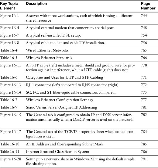
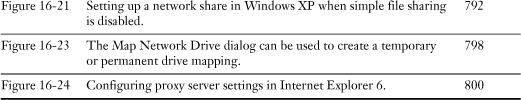
Complete the Tables and Lists from Memory
Print a copy of Appendix B, “Memory Tables,” (found on the CD), or at least the section for this chapter, and complete the tables and lists from memory. Appendix C, “Memory Tables Answer Key,” also on the CD, includes completed tables and lists to check your work.
Definitions of Key Terms
Define the following key terms from this chapter, and check your answers in the glossary.
LAN,
WAN,
DUN,
DSL,
ADSL,
SDSL,
HTTP,
HTTPS,
SSL,
TLS,
HTML,
FTP,
DNS,
SMTP,
POP3,
IMAP,
802.11a,
802.11g,
802.11n,
IrDA,
VoIP,
SSID,
WEP,
WPA,
Hub,
WINS,
Troubleshooting Scenario
You have a computer that has an issue connecting to network resources such as a printer or share on a server. What are some of the tests you can perform to fix this problem so the user can continue working?
Refer to Appendix A, “Answers to the ‘Do I Know This Already?’ Quizzes and Troubleshooting Scenarios,” for the answer.