
Chapter 12. Storage Devices
This chapter covers a portion of the CompTIA A+ 220-701 objectives 1.1, 1.2, and 2.5 and CompTIA A+ 220-702 objective 1.1 and 1.2.
Modern desktop computers feature a variety of storage devices, from the venerable floppy disk drive to its replacement, USB flash memory drives. Other typical storage devices include hard disk drives, CD and DVD optical drives, removable storage using tape cartridges or flash memory cards, and external storage devices of various types. The following sections teach you what you need to know about each item.
“Do I Know This Already?” Quiz
The “Do I Know This Already?” quiz allows you to assess whether you should read this entire chapter or simply jump to the “Exam Preparation Tasks” section for review. If you are in doubt, read the entire chapter. Table 12-1 outlines the major headings in this chapter and the corresponding “Do I Know This Already?” quiz questions. You can find the answers in Appendix A, “Answers to the ‘Do I Know This Already?’ Quizzes and Troubleshooting Scenarios.”
Table 12-1 “Do I Know This Already?” Foundation Topics Section-to-Question Mapping

1. Which of the following drives uses a 1.44MB disk to store data and can also be used for bootable diagnostics?
a. CD-ROM
b. Floppy disk
c. USB drive
d. External hard drive
2. Which of the following is installed in all computers and is used for storing the operating system?
a. USB drive
b. CD drive
c. Hard drive
d. Firewire drive
3. What is the sector size on the platter on a hard drive?
a. 1024 bytes
b. 750 bytes
c. 512 bytes
d. 128 bytes
4. What are the two listed interfaces that are used to connect CD-ROMs and DVD-ROMs to the computer?
a. ATA
b. IrDA
c. IDE
d. EIDE
5. You have just installed a CD-ROM drive to your computer. You want to listen to music so you insert a music CD into the drive. Windows Media Player starts up and you can see a song title and the elapsed time of the song within the player. Everything looks correct; however, for some reason you cannot hear the music. What could be the problem?
a. The power cable is not connected to the CD-ROM drive.
b. You need to connect the CD audio cable to the sound card.
c. You need to go the manufacturer’s website for an updated CD-ROM driver.
d. The CD is faulty.
6. What are the sizes available for the Iomega Zip removable storage drives? (Choose all that apply.)
a. 100MB
b. 250MB
c. 300GB
d. 750MB
7. Which of the following storage devices uses magnetic tape to store large amounts of data?
a. External hard drive
b. USB drive
c. ATA drive
d. Tape drive
8. You are in need of a device that will read the different types of memory cards. You purchase a flash card reader. How would you install this device on your computer?
a. Connect it to the motherboard
b. Connect it to an available USB port
c. Connect it to the serial port
d. Connect it to the removable disk drive slot
9. Which of the following devices is the best solution for quickly transferring data between systems and running utility programs?
a. USB drive
b. 3.5-inch floppy
c. 100 MB Zip drive
d. CD-ROM drive
10. You purchase a new USB memory drive. Which of the following file systems has this drive been pre-formatted with? (Select two.)
a. NTFS
b. NFS
c. FAT16
d. FAT32
11. Which of the following connections are used for external hard disks?
a. eSATA
b. USB
c. IEEE 1394
d. PCIe
12. You have just installed a new floppy drive on a computer. You notice that when you turn the computer on, the drive light stays on. What could be causing this problem?
a. The cable has been installed incorrectly.
b. The drive is faulty.
c. The drive has been installed improperly.
d. The BIOS has not been configured properly.
Foundation Topics
Floppy Disk Drives
Floppy drives are used primarily for backups of small amounts of data, for bootable diagnostic disks, and for the creation of bootable emergency disks with some versions of Windows. The 1.44MB floppy drive shown in Figure 12-1 and Figure 12-2 is found in some recent and virtually all older desktop and laptop computers, although many recent computers no longer use floppy drives. The 1.44MB drive uses 3.5-inch double-sided high-density (DSHD) media, and also supports the 720KB 3.5-inch double-sided double-density (DSDD) media used by 3.5-inch drives produced in the 1980s. Some older IBM systems used a 2.88MB DSED floppy drive, but were also compatible with 1.44MB and 720KB floppy disks.
Figure 12-1 A typical 3.5-inch floppy disk drive.
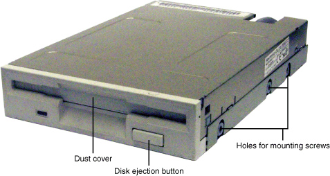
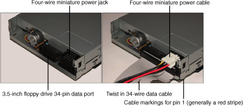
Figure 12-2 The rear of a typical 3.5-inch drive before (left) and after (right) data and power cables are attached.
![]()
Figure 12-1 shows the front and sides of a typical 3.5-inch floppy drive, and Figure 12-2 shows the data and power connectors used by 3.5-inch floppy drives.
Note
Most desktop systems that use 3.5-inch drives use internal drives (refer to Figure 12-1), but floppy drives can also be connected to the USB port.
In the following sections, you will learn about the different types of floppy disk drives and media, and how drives are installed, configured in the BIOS, and maintained.
Floppy Disk Types
Floppy drives use flexible magnetic media protected by a rigid plastic case and a retractable shutter. There have been three different types of 3.5-inch floppy disk media used over time, although only the 1.44MB floppy disk is used currently. Figure 12-3 compares the capacities and distinguishing marks of each disk type. Note that all 3.5-inch disks use the write-enable slider shown in Figure 12-3.
Figure 12-3 A 3.5-inch 720KB floppy disk (left) compared to a 1.44MB floppy disk (right), and a 2.88MB floppy disk (center).

Table 12-2 helps you distinguish between different disk types in use today.
Table 12-2 Physical Characteristics of 3.5-inch Floppy Media

Of the disks pictured in Figure 12-3, only the 3.5-inch DSHD disk is commonly used today. 1.44MB disks are often marked HD on their front and always have a media-sensing hole in the opposite corner from the write-enable/protect slider.
Note
Some older desktop and portable systems might use an LS-120 or LS-240 SuperDisk drive in place of a standard 1.44MB floppy drive. These drives can read and write 1.44MB and 720KB 3.5-inch floppy media, but can also use high-capacity 3.5-inch media. The LS-120 SuperDisk uses 120MB media, and the LS-240 SuperDisk can use 120MB or 240MB media. These drives usually plug into the ATA/IDE (PATA) interface if internal, or the parallel or USB port if external.
5.25-inch floppy drives were used before 3.5-inch drives became commonplace, but they have been obsolete for some years and are seldom used.
Floppy Disk Drive Hardware Configuration
Floppy disk drive hardware configuration depends on several factors, including
• Correct CMOS configuration— The system’s BIOS configuration screen must have the correct drive selected for A: and B:.
• Correct cable positioning and attachment— The position of the drive(s) on the cable determine which is A: and which is B:. If the cable is not oriented properly, the drive will spin continuously and the LED on the front of the drive will stay on.
Caution
If you insert disks into a floppy drive while the cable is reversed, the contents of the media can be damaged or the media can be rendered unusable.
The standard floppy disk drive interface uses a single IRQ and single I/O port address range, whether the interface is built in or on an expansion card:
• Floppy Drive IRQ: 6
• Floppy Drive I/O Port Address: 3F0–3F7h
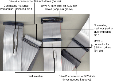
The standard floppy disk drive interface can support two drives: drive A: and drive B:. However, some recent systems support only one floppy drive (A:). The 34-pin floppy disk drive data cable has wires numbered 10 to 16 twisted in reverse between the connectors for drive A: and drive B:. The drive beyond the twist is automatically designated as drive A:; the drive connected between the twisted and the untwisted end of the cable (which connects to the floppy controller) is automatically designated as drive B:.
Figure 12-4 compares five-connector universal (3.5-inch/5.25-inch) and three-connector 3.5-inch floppy cables. (The cable connector to the floppy controller is not visible in this photo.)
Figure 12-4 Two types of floppy drive cables compared. On the left, a cable designed for 3.5-inch drives only; on the right, a cable designed for 3.5-inch and 5.25-inch drives.
Floppy Disk Drive Physical Installation and Removal
To install a 3.5-inch 1.44MB floppy disk drive as drive A:, follow these steps:
Step 1. Select an empty 3.5-inch external drive bay; an external drive bay is a drive bay with a corresponding opening in the case.
Step 2. Remove the dummy face plate from the case front.
Step 3. For an ATX tower system, remove the left side panel (as seen from the front). For a BTX tower system, remove the right side panel (as seen from the front). For a desktop system, remove the top.
Step 4. If the 3.5-inch drive bay is a removable “cage,” remove it from the system. This might involve pushing on a spring-loaded tab or removing a screw. Some drive bays pull straight out (as here), whereas others swing to one side.
Step 5. Remove the floppy disk drive from its protective packaging. Test the screws you intend to use to secure the drive and ensure they’re properly threaded and the correct length.
Step 6. Check the bottom or rear panel of the drive for markings indicating pin 1; if no markings are found, assume pin 1 is the pin closest to the power supply connector.
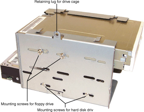
Step 7. Secure the drive to the drive bay with the screws supplied with the drive or with the computer (see Figure 12-5).
Figure 12-5 A removable drive cage with the attachment screws for the floppy disk drive and hard drive. The opposite side of each drive is also secured with screws (not shown).
Step 8. Replace the drive bay into the computer.
Step 9. Attach the 34-pin connector at the end of the floppy disk drive data cable with the twist to the data connector on the drive.
Step 10. Run the other end of the floppy disk drive data cable through the drive bay into the interior of the computer. Then, connect it to the floppy disk drive interface on the motherboard or add-on card.
Step 11. Attach the correct type of four-wire power cable to the drive. You might need to slide the drive part way into the drive bay to make the connection.
Step 12. Double check power and data cable keying before starting the computer.
Step 13. Follow these steps in reverse to remove the drive from the system.
Floppy Drive BIOS Configuration
Floppy disk drives cannot be detected by the system; you must manually configure the floppy disk drive or floppy disk drives you add to the system.
To configure the floppy disk drive in the ROM BIOS, follow these steps:
Step 1. Verify the correct physical installation as listed previously.
Step 2. Turn on the monitor and the computer.
Step 3. Press the appropriate key(s) to start the BIOS configuration program.
Step 4. Open the standard configuration menu.
Step 5. Select Drive A: or the first floppy disk drive.
Step 6. Use the appropriate keys to scroll through the choices; 3.5-inch 1.44MB is the correct choice for virtually all systems with an onboard floppy drive (see Figure 12-6).
Figure 12-6 Viewing floppy drive type options in the BIOS setup program of a typical system.
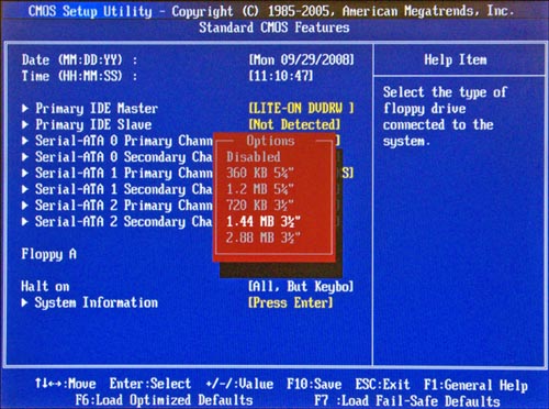
Step 7. No other changes are necessary, so save your changes and exit to reboot the system.
If you only need a floppy drive for occasional use, you can connect an external floppy drive to the USB port. If you need to boot from an external floppy drive or need to load drivers from it during the installation of Windows, check the system BIOS setup program to verify that the drive is listed as a bootable device.
Maintaining Floppy Disks, Data, and Drives
You can protect the data on your floppy disks by following these recommendations; most of these suggestions also apply to higher-capacity magnetic removable media such as Zip, REV, and tape backups:
• Do not open the protective metal shutter on 3.5-inch disks or tape backups.
• Do not touch the magnetic media itself.
• Store disks away from sources of magnetism (CRT monitors, magnetized tools, unshielded speakers, and unshielded cables) or heat.
• Open the sliding write-protect hole on 3.5-inch disks to prevent the contents of the disk from being changed.
Floppy disk drives are a type of magnetic storage in which the read/write heads make direct contact with the media. This is similar to the way that tape drives work, and just like tape backup, music cassette, or VCR heads, a floppy disk drive’s read/write heads can become contaminated by dust, dirt, smoke, or magnetic particles flaking off the disk’s media surfaces. For this reason, periodic maintenance of floppy disk drives will help to avoid the need to troubleshoot drives that cannot reliably read or write data.
The following are some guidelines for cleaning a floppy disk drive:
• Approximately every six months, or more often in dirty or smoke-filled conditions, use a wet-type head-cleaning disk on the drive.
These cleaning kits use a special cleaning floppy disk that contains cleaning media in place of magnetic media, along with an alcohol-based cleaner. Add a few drops to the media inside the cleaning disk, slide it into the drive, and activate the drive with a command such as DIR or by using Windows Explorer; as the read/write heads move across the cleaning media, they are cleaned. Allow the heads to dry for about an hour before using the drive.
• Whenever you open a system for any type of maintenance or checkup, review the condition of the floppy disk drive(s). Use compressed air to remove fuzz or hair from the drive heads and check the mechanism for smooth operation.
Hard Disk Drives
Hard disk drives are the most important storage device used by a personal computer. Hard disk drives store the operating system (Windows, Linux, or others) and load it into the computer’s memory (RAM) at startup. Hard disk drives also store applications, system configuration files used by applications and the operating system, and data files created by the user.
Hard disk drives use one or more double-sided platters formed from rigid materials such as aluminum or glass. These platters are coated with a durable magnetic surface that is divided into sectors. Each sector contains 512 bytes of storage along with information about where the sector is located on the disk medium. Sectors are organized in concentric circles from the edge of the media inward toward the middle of the platter. These concentric circles are called tracks.
Hard disk drives, unlike floppy drives, are found in every PC. Internal hard disk drives for desktop computers use the same 3.5-inch form factor as floppy drives, but are installed into internal drive bays. Their capacities range up to 1TB, but most desktop drives in recent systems have capacities ranging from 160GB to 500GB.
The most common types of hard disk interfaces in current PCs are Serial ATA (SATA) and Parallel ATA (PATA). PATA is also known as ATA/IDE. Both SATA and PATA interfaces can also be used by optical drives (CD and DVD), removable-media drives such as Zip and REV, and tape backup drives.
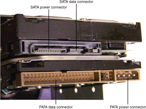
Figure 12-7 compares typical SATA and PATA hard disks to each other.
Figure 12-7 The power and data cable connectors on SATA and PATA (ATA/IDE) hard disks.
![]()
In the following sections, you will learn about the data and power cables used by SATA and PATA drives, how PATA drives are configured by jumper blocks, the various ATA specifications, how PATA and SATA drives are installed, how to configure PATA and SATA drives in the system BIOS, and how to improve PATA drive performance.
PATA and SATA Data and Power Cables
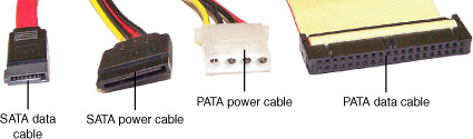
PATA drives use a 40-pin data cable, while SATA drives use an L-shaped seven-wire data cable. PATA drives use a five-pin Molex power cable, while SATA drives use an L-shaped power cable. Figure 12-8 compares PATA and SATA power and data cables.
Figure 12-8 The power and data cables used by SATA and PATA (ATA/IDE) hard disks.
![]()
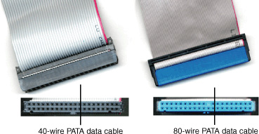
One or two PATA hard disks or other types of ATA/IDE drives can be connected to a single data cable. Current hard disk designs use an 80-wire cable, while CD/DVD and removable-media drives can use either the 80-wire cable or the older 40-wire design. Figure 12-9 compares these cables to each other.
Figure 12-9 40-wire and 80-wire PATA data cables. 80-wire cables are required by modern PATA hard disks and recommended for other types of PATA devices.
PATA Drive Jumpering and Cable Select
PATA drives are identified as primary/secondary or master/slave. To make this determination, jumper blocks on the drive (usually on the rear, but occasionally on the bottom) are used (See Figure 12-10).
Figure 12-10 Two typical PATA (ATA/IDE) drives configured for cable select. Some drives, such as the one on the left, require the user to consult a chart on the drive’s top plate or in the system documentation for correct settings, whereas others silk-screen the jumper settings on the drive’s circuit board.
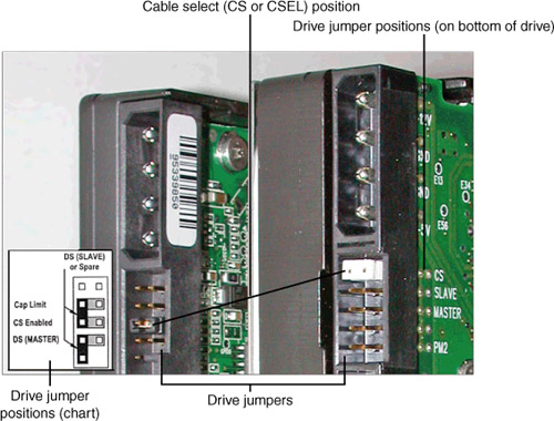
With an 80-wire cable, jumper blocks on both drives are set to Cable Select (CS), and the drive’s position on the cable determines primary/secondary:
• The blue connector on the cable plugs into the PATA host adapter on the motherboard or add-on card.
• The gray connector in the middle of the cable is used for the secondary (slave) drive.
• The black connector on the far end of the cable is used for the primary (master) drive.
The older 40-wire cable uses only jumper blocks to determine drive configuration. When a single drive is installed on a cable, the drive is configured as master or single. When two drives are installed on a cable, one is configured as master (primary) and the other as slave (secondary).
Only one SATA drive can be connected to an SATA host adapter port, so jumper blocks are unnecessary.
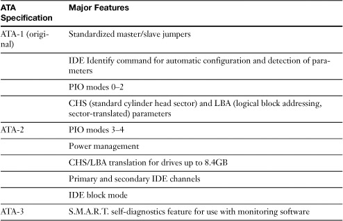
ATA Specifications
A series of standards for ATA/IDE and SATA drives are referred to as the ATA specifications (AT Attachment). Table 12-3 provides an overview of the differences in the various ATA specifications.
Table 12-3 ATA Specifications and Features

![]()
ATA/IDE Drive Physical Installation
The following steps apply to typical ATA/IDE drive installations of hard disks, optical (CD/DVD) drives, removable-media drives, or tape drives:
Step 1. Open the system and check for an unused 3.5-in drive bay or an unused 5.25-inch drive bay. The 3.5-inch drive bay is used for hard disks and some tape and removable-media drives. The 5.25-inch drive bay is used for optical drives and can be used for other types of drives as well.
Step 2. For 3.5-inch drives: If a 3.5-inch drive bay is not available but a 5.25-inch drive bay is, attach the appropriate adapter kit and rails as needed, as shown in Figure 12-11.
Figure 12-11 A typical adapter kit for a 3.5-inch drive. Screw a attaches the frame at hole #1; screw b attaches the frame at hole #2, with corresponding attachments on the opposite side of the drive and frame. Drive rails used by some cases can be attached to the adapter kit.
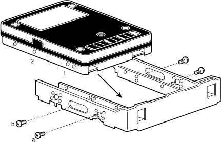
For 5.25-inch drives: If the 5.25-inch drive bays on the system use rails to hold drives in position, attach the appropriate rails.
Step 3. Jumper the drive according to the cable type used: 40-wire cables use master and slave; 80-wire cables use cable select or master and slave. Use only 80-wire cables for hard disks. Other types of drives can use 40-wire or 80-wire cables, but 80-wire cables are preferred.
Step 4. Attach the appropriate connector to the drive, making sure to match the colored marking on the edge of the cable to the end of the drive connector with pin 1. Pin 1 might be marked with a square solder hole on the bottom of the drive or silk-screening. If no markings are visible, pin 1 is usually nearest the drive’s power connector. Disconnect the cable from the host adapter or other ATA/IDE drive if necessary to create sufficient slack.
Step 5. Slide the drive into the appropriate bay and attach as needed with screws or by snapping the ends of the rails into place.
Step 6. Attach the power connector; most PATA hard drives use the larger four-wire (Molex) power connector originally used on 5.25-inch floppy disk drives. Use a Y-splitter to create two power connectors from one if necessary.
Step 7. Reattach the data cable to the other ATA or ATAPI drive and host adapter if necessary.
Step 8. Change the jumper on the other ATA or ATAPI drive on the same cable if necessary. With 80-wire cables, both drives can be jumpered as Cable Select, with the drive at the far end of the cable being treated as master, and the middle drive as slave. With 40-wire cables, only Master and Slave jumper positions are used with most brands. See the drive markings or documentation for details.
Note
Move the jumper simply by grasping it with a pair of tweezers or small needle-nose pliers and gently pulling straight backward. It’s always best to change jumper settings before inserting the drive into the PC because they can be especially difficult to reach after the drive is installed.
Step 9. Verify correct data and power connections to all installed drives and host adapters.
Step 10. Turn on the system and start the BIOS configuration program.
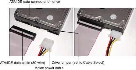
Figure 12-12 shows a typical ATA/IDE drive before and after power and data cables are attached.
Figure 12-12 Attaching power and data cables to a typical ATA/IDE drive.
![]()
SATA Hard Drive Physical Installation
The process of installing an SATA drive differs from that used for installing an ATA/IDE drive because there are no master or slave jumpers and the SATA data cable goes directly from host adapter to drive. The following instructions assume the system has an onboard or add-on card SATA host adapter already installed. If you need to install an SATA host adapter, see the next section for details.
Step 1. Open the system and check for an existing 3.5-inch drive bay; use an internal bay if possible.
Step 2. If a 3.5-inch drive bay is not available but a 5.25-inch drive bay is, attach the appropriate adapter kit and rails as needed, as shown previously in Figure 12-11.
Step 3. Attach the SATA cable to the drive; it is keyed so it can only be connected in one direction.
Step 4. Slide the drive into the appropriate bay and attach as needed with screws or by snapping the ends of the rails into place.
Step 5. Attach the power connector; use the adapter provided with the drive to convert a standard Molex connector to the edge connector type used by SATA. If the drive didn’t include a power connector, purchase one.
Step 6. Attach the data cable to the host adapter.
Step 7. Verify correct data and power connections to IDE drives and host adapters.
Step 8. Turn on the system and start the BIOS configuration program if the SATA host adapter is built into the motherboard. Enable the SATA host adapter, save changes, and restart your system.
Step 9. If the SATA drive is connected to an add-on card, watch for messages at startup indicating the host adapter BIOS has located the drive. See the section “SATA BIOS Configuration,” later in this chapter, for details.
Step 10. Install drivers for your operating system to enable the SATA drive and host adapter to function when prompted. See Chapter 14, “Installing and Upgrading Windows Operating Systems,” for details.
Figure 12-13 shows a typical SATA drive before and after attaching power and data cables. Figure 12-14 shows typical PATA and SATA host adapter connections on a recent motherboard.
Figure 12-13 Attaching power and data cables to a typical SATA drive.
![]()
Figure 12-14 PATA and SATA host adapters on a recent motherboard.

Installing an SATA Host Adapter
Some older systems don’t include an SATA host adapter on the motherboard. Thus, to add an SATA drive to these systems, you will also need to install an SATA host adapter card such as the one pictured in Figure 12-15. Follow this procedure:
Figure 12-15 A typical SATA host adapter card that supports two SATA drives. The inset shows how this host adapter appears in the Windows XP Device Manager after installation.

Step 1. Shut down the system and disconnect the power cable from the outlet to cut all power to the system.
Step 2. Use ESD protection equipment, such as a wrist strap and work mat, if available. (See Chapter 17, “Safety and Environmental Issues,” for details.)
Step 3. Open the computer and locate an unused PCI slot.
Step 4. After removing the slot cover, insert the SATA card into the slot. See Chapter 3, “Motherboards, Processors, and Adapter Cards,” for basic instructions on adding expansion cards, such as the SATA host adapter described here.
Step 5. Secure the card into place with the screw removed from the slot cover.
Step 6. Connect the card to the SATA drive with an SATA data cable. The cable might be provided with the card or with the drive.
Step 7. Reconnect the power cord and restart the computer.
Step 8. Install drivers when prompted.
Step 9. Restart your computer if prompted.
Step 10. Open Windows Device Manager to verify that the SATA host adapter is working. It should be listed under the category SCSI Controllers, SCSI Adapters, or SCSI and RAID Controllers (see Figure 12-15).
PATA BIOS Configuration
For PATA drives controlled by the motherboard BIOS, the following information must be provided to the BIOS:
• Hard drive geometry
• Data transfer rate
• LBA translation
Hard drive geometry refers to several factors used to calculate the capacity of a hard drive. These factors include the following:
• The number of sectors per track
• The number of read/write heads
• The number of cylinders
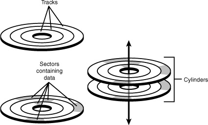
The surface of any disk-based magnetic media is divided into concentric circles called tracks. Each track contains multiple sectors. A sector contains 512 bytes of data and is the smallest data storage area used by disk drives.
Note
Although floppy disks also have tracks and sectors, modern operating systems do not require you to specify the track layout of the disk when formatting the media.
Each side of a hard disk platter used for data storage has a read-write head which moves across the media. There are many tracks on each hard disk platter, and all the tracks on all the platters are added together to obtain the cylinder count.
Figure 12-16 helps you visualize sectors, tracks, and cylinders.
Figure 12-16 Tracks, sectors, and cylinders compared.
Before the drive can be prepared by the operating system, it must be properly identified by the system BIOS.
Most system BIOS programs are designed to perform auto-detection, reading the appropriate configuration from the drive itself. When installing a drive, make sure the system detects the hard disk (see Figure 12-17). After the drive is detected, the changes to the CMOS setup should be saved, the system rebooted, and the drive prepared for use.
Figure 12-17 Configuring a 160GB Maxtor PATA drive with the auto-detection feature in a typical system BIOS.
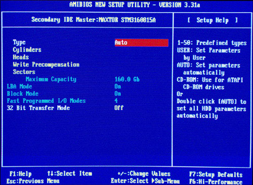
Auto-detection is the best way to install a new PATA drive because other settings such as LBA translation, block mode (multisector transfers), and UDMA transfer rates will also be configured properly.
Note
If LBA translation is turned off in the system BIOS, only 8.4GB of the hard disk’s capacity will be recognized by the system BIOS. If disk writes take place while a drive prepared with LBA translation is being accessed without LBA translation, data could be corrupted or overwritten.
Some BIOS programs perform the automatic detection of the drive type every time you start the system by default. Although this enables you to skip configuring the hard drive setting, it also takes longer to start the system and prevents the use of nonstandard configurations for compatibility reasons.
Depending on the system, removable-media ATAPI (ARMD) drives such as Zip and LS-120 should be configured as Not Present or Auto in the system BIOS setup or as ARMD drives depending upon the BIOS options listed. These drives do not have geometry values to enter in the system. The CD-ROM setting should be used for ATAPI CD-ROM and similar optical drives, such as CD-R, CD-RW, and DVD. Using the correct BIOS configuration for ATAPI drives will enable them to be used to boot the system on drives and systems that support booting from ATAPI devices.
SATA BIOS Configuration
Before you can install an SATA hard disk to an SATA host adapter on the motherboard, you must make sure the host adapter is enabled in the system BIOS (see Figure 12-18).
Figure 12-18 Enabling an onboard SATA host adapter.

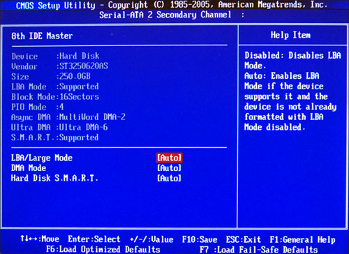
After the SATA host adapter is enabled, save changes to the BIOS and shut down the system. After connecting the SATA drive to one of the onboard SATA host adapters, restart the system and reenter the BIOS setup program. Verify that the system has detected the SATA drive (see Figure 12-19). Save changes to the BIOS, restart, and prepare the hard disk for use.
Figure 12-19 Auto-detecting an SATA hard disk.
Creating an ATA or SATA RAID Array
RAID (redundant array of inexpensive drives) is a method for creating a faster or safer single logical hard disk drive from two or more physical drives. RAID arrays have been common for years on servers using SCSI-interface drives. However, a number of recent systems feature ATA RAID or SATA RAID host adapters on the motherboard. ATA and SATA RAID host adapter cards can also be retrofitted to systems lacking onboard RAID support. These types of RAID arrays are also referred to as hardware RAID arrays. RAID arrays can also be created through operating system settings, and are sometimes called software RAID arrays. However, software RAID arrays are not as fast as hardware RAID arrays.
ATA and SATA RAID types include the following:
• RAID Level 0 (RAID 0)— Two drives are treated as a single drive, with both drives used to simultaneously store different portions of the same file. This method of data storage is called striping. Striping boosts performance, but if either drive fails, all data is lost. Don’t use striping for data drives.
• RAID Level 1 (RAID 1)— Two drives are treated as mirrors of each other; changes to the contents of one drive are immediately reflected on the other drive. This method of data storage is called mirroring. Mirroring provides a built-in backup method and provides faster read performance than a single drive. Suitable for use with program and data drives.
• RAID Level 0+1 (RAID 10)— Four drives combine striping plus mirroring for extra speed plus better reliability. Suitable for use with program and data drives.
• RAID Level 5 (RAID 5)— Three or more drives are treated as a logical array, and parity information (used to recover data in the event of a drive failure) is spread across all drives in the array. Suitable for use with program and data drives.
Table 12-4 provides a quick comparison of these types of RAID arrays.
Table 12-4 Comparisons of RAID Levels
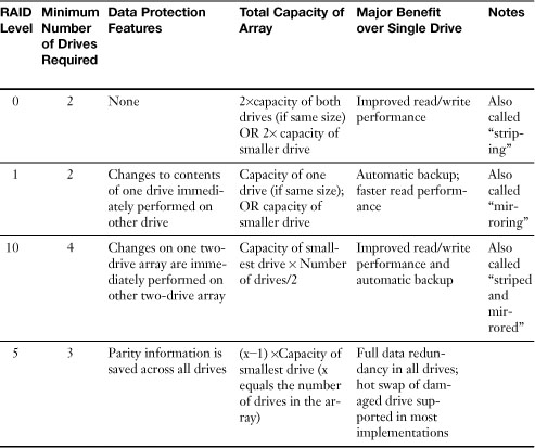
Motherboards that support only two drives in a RAID array support only RAID 0 and RAID 1. Motherboards that support more than two drives can also support RAID Level 0+1, and some support RAID 5 as well. RAID-enabled host adapter support varying levels of RAID.
Note
ATA or SATA RAID host adapters can sometimes be configured to work as normal ATA or SATA host adapters. Check the system BIOS setup or add-on card host adapter setup for details.
An ATA or SATA RAID array requires
• Two or more identical drives— If some drives are larger than others, the additional capacity will be ignored. See Table 12-4 above.
• A RAID-compatible motherboard or add-on host adapter card— Both feature a special BIOS, which identifies and configures the drives in the array.
Because RAID arrays use off-the-shelf drives, the only difference in the physical installation of drives in a RAID array is where they are connected. They must be connected to a motherboard or add-on card that has RAID support.
Note
Sometimes ATA RAID connectors are made from a contrasting color of plastic than other drive connectors. However, the best way to determine if your system or motherboard supports ATA or SATA RAID arrays is to read the manual for the system or motherboard.
After the drive(s) used to create the array is connected to the RAID array’s host adapter, restart the computer. Start the system BIOS setup program and enable the RAID host adapter if necessary. Save changes and exit the BIOS setup program.
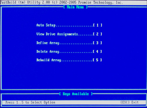
After enabling the RAID array host adapter, follow the vendor instructions to create the array. Generally, this requires you to activate the RAID array setup program when you start the computer (Figure 12-20 shows a typical RAID setup program) and follow the prompts to select the type of array desired. After the RAID array is configured, the drives are handled as a single physical drive by the system.
Figure 12-20 Preparing to create an ATA RAID array.
![]()
Caution
If one or more of the drives to be used in the array already contains data, back up the drives before starting the configuration process! Most RAID array host adapters delete the data on all drives in the array when creating an array, sometimes with little warning.
Note
If you want to create a striped volume (equivalent to RAID 0) in Windows XP or Windows Vista but your system does not include PATA RAID or SATA RAID host adapters, you can use Computer Management Console’s Disk Management node (diskmgmt.msc).
To create a striped volume, use the New Volume wizard from the right-click menu, and select Striped as the volume type. After selecting one or more additional drives and adding them to the volume, you are prompted to assign the volume a new drive letter, mount the volume to an empty NTFS folder on another drive, or do nothing. After the array is formatted, it can then be used. Note that Windows cannot create a mirrored volume.
ATA/IDE Performance Optimization
If your hard drive is stuck in first gear, so is your system. Fortunately, most systems that support LBA mode also offer several different ways to optimize the performance of IDE drives and devices. These include
• Selecting the correct PIO or DMA transfer mode in the BIOS
• Selecting the correct block mode in the BIOS
• Installing busmastering Windows drivers
• Enabling DMA mode in Windows
• Adjusting disk cache software settings
PIO and DMA Transfer Modes
PATA (ATA/IDE) storage devices are capable of operating at a wide variety of transfer speeds. Virtually all recent hard disk and other drives support one of various Ultra DMA (UDMA) modes (also known as Ultra ATA modes).
The correct speed is determined when the drive is detected by the computer during CMOS setup. However, if you use a 40-wire PATA cable, the fastest Ultra DMA speed available is Ultra DMA 33. For this reason, you should use 80-wire cables for hard disks and other PATA storage devices.
To achieve a given transfer rate, the hard disk, the host adapter (card or built-in), and the data cable must be capable of that rate. In addition, the host adapter must be configured to run at that rate.
Table 12-5 lists the most common transfer rates. Check the drive documentation or with the drive vendor for the correct rating for a given drive.
Table 12-5 UDMA (Ultra ATA) Peak Transfer Rates

![]()
These modes are backward compatible, enabling you to select the fastest available mode if your system lacks the correct mode for your drive. ATA/IDE drives are backward compatible; you can select a slower UDMA mode than the drive supports if your system doesn’t support the correct UDMA mode. Performance will be slower, but the drive will still work.
Tip
Some older UDMA drives are shipped with their firmware configuration set to a lower transfer rate than the maximum supported by the drive. This helps avoid data loss that could happen if the drive were connected to a system that doesn’t support the drive’s maximum transfer rate. Fortunately, these drives usually include a software utility that can ratchet up the speed to the maximum allowed. If you can’t find the driver disk or CD, check out the vendor’s website for the utility and download it.
If a particular drive and host adapter combination is not capable of running at any UDMA speed, the system will revert to the slower PIO drive access method. PIO transfer rates are shown in Table 12-6.
Table 12-6 PIO Peak Transfer Rates
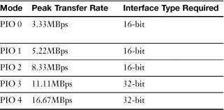
As you can see from Table 12-6, even the fastest PIO mode is only half the speed of the slowest UDMA mode.
IDE Block Mode
IDE block mode refers to multi-sector data transfers. Originally, a PATA hard drive was allowed to read only a single 512-byte sector before the drive sent an IRQ to the CPU. Early in their history, some PATA hard drives began to use a different method called block mode, which enabled the drive to read multiple sectors, or blocks, of data before an IRQ was sent. All recent drives support block mode, and the correct value is configured when the drive is detected. If block mode is disabled, a drive that supports block mode transfers data more slowly.
Note
Some very old ATA/IDE drives do not support block mode and run more slowly when it is enabled.
IDE Busmastering Drivers
A third way to improve IDE hard disk performance is to install busmastering drivers for the IDE host interface. A busmaster bypasses the CPU for data transfers between memory and the hard disk interface. This option is both operating system–specific and motherboard/host adapter–specific.
If you have installed a new motherboard, busmastering drivers are provided on a driver CD or floppy disk. They are preinstalled on complete systems. You might find more up-to-date versions at the vendor’s website or by running Windows Update. Because busmastering bypasses the CPU, be sure you are installing the correct drivers. Carefully read the motherboard or system vendor’s instructions.
Enabling DMA Transfers for PATA Devices in Windows
All versions of Windows from Windows NT 4.0 (Service Pack 3 and greater) and Windows 95 through Windows Vista enable the user to allow DMA transfers between PATA devices and the system. DMA transfers bypass the CPU for faster performance and are particularly useful for optimizing the performance of both hard drives and optical drives, such as high-speed CD-ROM drives and DVD drives.
Note
The correct busmastering drivers for your system and Windows version must be installed before you can enable DMA transfers.
Follow this procedure to enable DMA transfers for a particular IDE host adapter in Windows 2000/XP/Vista:
Step 1. Open the System Properties sheet. Right-click My Computer and select Properties, or open the Control Panel and select System.
Step 2. Click Hardware, Device Manager. (In Windows Vista, just click Device Manager under Tasks.)
Step 3. To determine which drives are connected to which host adapter, open the category containing the drives (Disk Drives for hard or removable-media drives or DVD/CD-ROM Drives for optical drives) and double-click the drive to open its Properties sheet. The location value visible on the General tab shows to which host adapter and device number the drive is connected. For example, location 0 (1) indicates the drive is connected to the primary host adapter (0) as the secondary device (1).
Step 4. Click the plus sign next to the IDE ATA/ATAPI Controllers category.
Step 5. Double-click the host adapter for which you want to adjust properties (primary or secondary IDE channel) to open its Properties sheet.
Step 6. Click Advanced Settings.
Step 7. To enable DMA for a particular drive, select DMA if available for the Transfer mode. To disable DMA, select PIO only (see Figure 12-21). (In Windows Vista you would just select the checkbox labeled Enable DMA.)
Figure 12-21 The secondary IDE channel on this system is configured to run one drive in PIO mode and one drive in UDMA mode.

Step 8. Click OK.
Step 9. Restart the computer as prompted.
If DMA is not available, you might need to install the correct busmastering driver for your system.
Caution
Before enabling DMA or UDMA mode, check the documentation for the drive to see if it supports this mode. Enabling DMA or UDMA on a drive that does not support it can have disastrous effects.
If the drive can’t go faster than UDMA 2 although it’s rated for higher speeds (see Figure 12-21), you might want to change the cable. You must use the 80-wire cable shown earlier in Figure 12-9 to run at UDMA 4 (66MBps) or faster transfer rates. It’s also okay to use the 80-wire cable for slower transfer rates.
Adjusting Disk Caching Settings in Windows
Disk caches use a portion of memory to hold information flowing to and from disk drives. The system accesses the cache memory before accessing the main memory. If the information on disk is already in the cache memory, it is accessed far more quickly than if it were read from disk.
To adjust disk-cache settings for Windows 2000/XP (not Vista), follow this procedure:
Step 1. Open the System Properties sheet and click Advanced.
Step 2. Click the Settings button in the Performance section.
Step 3. Click Advanced.
Step 4. Click System Cache to use more memory on a computer that provides server features to other computers or to improve overall disk-caching performance. To avoid reducing system performance, you should enable this feature only on systems with 512MB of RAM or more.
Step 5. Click OK and restart the system as prompted.
CD and DVD Optical Drives
Optical drives fall into two major categories:
• Those based on CD technology, including CD-ROM, CD-R (recordable CD), and CD-RW (rewritable CD)
• Those based on DVD technology, including DVD-ROM, DVD-RAM, DVD-R/RW, DVD+R/RW, and DVD±R/RW
Both CD and DVD drives store data in a continuous spiral of indentations called pits and lands on the nonlabel side of the media from the middle of the media outward to the edge. All drives use a laser to read data; DVD stores more data because it uses a laser on a shorter wavelength than CD-ROM and CD-RW drives do, allowing for smaller pits and lands and more data in the same space. Most CD and DVD drives are tray-loading, but a few use a slot-loading design. Slot-loading designs are more common in home and automotive electronics products.
CD-R and CD-RW drives use special media types and a more powerful laser than that used on CD-ROM drives to write data to the media. CD-R media is a write-once media—the media can be written to during multiple sessions, but older data cannot be deleted. CD-RW media can be rewritten up to 1,000 times. 80-minute CD-R media has a capacity of 700MB, while the older 74-minute CD-R media has a capacity of 650MB. CD-RW media capacity is up to 700MB, but is often less, depending upon how the media is formatted.
Similarly, DVD-R and DVD+R media is recordable, but not erasable, whereas DVD-RW and DVD+RW media uses a phase-change medium similar to CD-RW and can be rewritten up to 1,000 times. DVD-RAM can be rewritten up to 100,000 times, but DVD-RAM drives and media are less compatible with other types of DVD drives and media than the other rewritable DVD types, making DVD-RAM the least popular DVD format.
• DVD-RAM— A rewriteable/erasable media similar to CD-RW but more durable; it can be single sided (4.7GB) or double sided (9.4GB).
• DVD-R— A writeable/nonerasable media similar to CD-R; capacity of 4.7GB; some DVD-RAM and all DVD-RW drives can use DVD-R media. DL media includes a second recording layer (capacity of 8.4GB).
• DVD-RW— A single-sided rewriteable/erasable media similar to CD-RW; capacity of 4.7GB. DVD-RW drives can also write to DVD-R media.
• DVD+RW— A rewritable/erasable media. Also similar to CD-RW, but not interchangeable with DVD-RW or DVD-RAM; capacity of 4.7GB.
• DVD+R— A writeable/nonerasable media. Also similar to CD-R, but not interchangeable with DVD-R; capacity of 4.7GB. DL media includes a second recording layer (capacity of 8.4GB).
So-called SuperMulti DVD drives can read and write all types of DVD media as well as CD media.
Drive speeds are measured by an X-rating:
• When working with CD media, 1X equals 150KBps, the data transfer rate used for reading music CDs. Multiply the X-rating by 150 to determine the drive’s data rate for reading, writing, or rewriting CD media.
• When working with DVD media, 1X equals 1.385MBps; this is the data transfer rate used for playing DVD-Video (DVD movies) content. Multiply the X-rating by 1.385 to determine the drive’s data rate for reading, writing, or rewriting DVD media.
CD and DVD Drive Interfaces
Most internal CD and DVD drives use the same ATA/IDE interface used by PATA hard disks. When this interface is used by drives other than hard disks, it is often referred to as the ATAPI interface. Some recent rewritable DVD drives use the SATA interface. External CD and DVD drives typically use the USB 2.0 interface. Some internal and external CD drives used the SCSI or Parallel (LPT) interfaces, but these drives are obsolete.
Physical Installation of Optical Drives
The installation of these drives follows the standard procedure used for each interface type:
• Internal optical drives must be installed into 5.25-inch drive bays.
• ATAPI/IDE optical drives must be configured as master, slave, or cable select (depending upon the cable type and other drives on the same cable).
• SCSI optical drives must be set to a unique device ID.
• SATA optical drives do not require special configuration.
• USB and IEEE-1394a optical drives must be connected to ports with adequate hub power, or they must provide their own power.
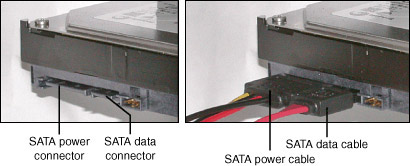
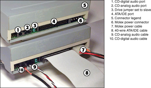
If you want to play music CDs through your sound card’s speakers, especially with older versions of Windows, you might need to connect a CD audio patch cable (it may be supplied with the drive or sold separately) to the CD audio jack on the sound card or motherboard audio support. Older drives support a four-wire analog cable, whereas newer drives support both the four-wire analog and newer two-wire digital cable. The digital cable provides for faster speed when ripping music CDs (ripping is the process of converting music CD tracks into compressed digital music files such as MP3 and WMA). Figure 12-22 shows a typical internal PATA (ATAPI) optical drive before and after connecting power, data, and music cables.
Figure 12-22 A typical ATAPI (PATA) internal optical drive before (top) and after (bottom) data, power, and CD music cables have been attached.
![]()
Note
Although internal optical drives support four-wire analog audio and two-wire digital audio cables, you do not need to install these cables to permit CD audio playback unless you use versions of Windows or music playback applications that do not support ripping or playback from the ATA/IDE or SATA interface.
Recording CDs and DVDs in Windows XP
All optical drives except for DVD-RAM drives are treated as CD-ROM or DVD-ROM drives by all versions of Windows; DVD-RAM drives are recognized as rewritable drives by all versions of Windows.
Windows XP provides rudimentary CD-R/RW recording capabilities with both CD-R/RW and rewritable DVD drives. However, commercial CD/DVD rewriting and mastering software such as Nero, Roxio Easy Media Creator, and others is highly recommended with Windows XP (and is required if you want to write to DVDs), and is required with older versions of Windows in order to use the rewritable/recordable features of CD and DVD drives. Most rewritable drives sold at stores are equipped with some version of one or more of these programs. However, some computer vendors rely on the Windows XP recording feature to support their bundled CD-RW drives.
Windows XP’s CD writing capability is automatically activated for any CD or DVD rewritable drive (although only CD-R/RW media is supported). To write files to the drive, insert a blank disc, drag files to the CD/DVD drive icon using Windows Explorer/My Computer, and click the CD/DVD drive icon. When the drive icon opens, files waiting to be written are listed. Click the task menu option Write These files to CD (see Figure 12-23).
Figure 12-23 Preparing to write files to a CD using the Windows XP CD-writing wizard.
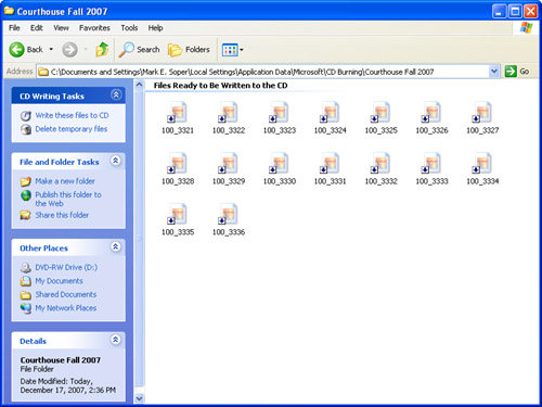
The files are written, albeit much more slowly than if you use a commercial CD-mastering or packet-writing program. When the files are written to disc, you will be prompted to insert another disc or to close the wizard.
To erase files from a CD-RW disc, place the disc in the drive, open its icon in Windows Explorer/My Computer, select the file(s) to erase, and press the Del key to erase them.
Note
Because Windows XP doesn’t format a CD-RW disc the same way a packet-writing program such as Drag to Disc, InCD, or DLA does, you cannot use a third-party program to erase files from a CD-RW disc written by Windows XP. You must use Windows XP to erase unwanted files. You can then reformat the media as desired with a different program.
Recording CDs and DVDs in Windows Vista
Windows Vista adds support for recordable and rewritable DVDs, and also adds additional functionality to the CD- or DVD-writing process. When you copy files to a recordable/rewritable CD or DVD drive using Windows Explorer, Send To, or other commands, Windows prompts you to insert a blank disc, and prompts you for a disc title. However, if you click on the Show Formatting Options button, you can also choose how to format the disc (see Figure 12-24).
Figure 12-24 Selecting a disc format with Windows Vista’s CD/DVD-writing wizard.
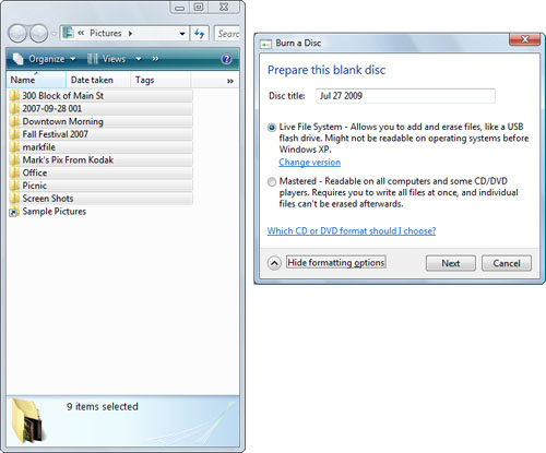
After selecting a format, click Next to continue. After the disc is formatted, Windows copies the files to the drive and displays a progress bar. At the end of the process, Windows displays the contents of the newly written CD or DVD.
If you use the Live File System, open Windows Explorer, right-click the disc, and select Eject so that the media will be prepared for use on other computers.
Note
When you use either Windows XP or Windows Vista to create CDs (or DVDs), you might have an AutoPlay dialog appear during the process. If you don’t want to use any of the options on the AutoPlay menu, or you have already begun a process, close it.
IDE/ATAPI Optical Drive Installation Issues
On systems using PATA hard disks and ATAPI optical or removable-media drives, PATA hard disks should be connected to the primary IDE interface and other types of drives should be connected to the secondary IDE interface.
Be sure to select the specific type of drive (CD-ROM, Zip, or other; use CD-ROM for CD or DVD drives) as the drive type, when offered, in the BIOS drive setup menu. If you want to boot from an optical drive, be sure that the optical drive is specified as the first device in the boot order.
Removable Storage
Removable storage is a blanket term for any type of drive that uses removable media, including both tape and disk-based technologies.
Current removable-storage devices that use disk technologies include
• Iomega Zip (100, 250, 750MB)— Zip drives use flexible media inside a rigid cartridge.
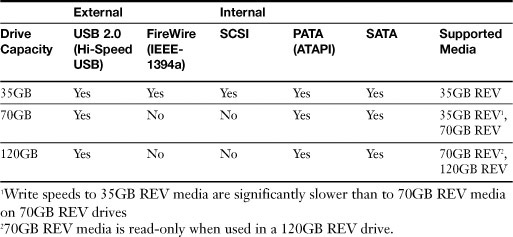
• Iomega REV (35GB, 70GB)— REV drives use hard disk-type media inside a rigid cartridge.
Both Iomega Zip and REV drives are available in both internal and external versions. See Table 12-7 (Zip) and Table 12-8 (REV).
Table 12-7 Iomega Zip Drive Interfaces and Capacities
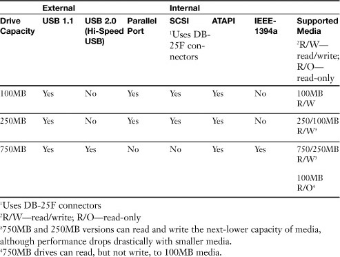
Table 12.8 Iomega REV Drive Interfaces and Capacities
REV drives are also available in autoloader designs that permit backups that require multiple REV disks to be performed automatically. Other types of removable storage used in recent years are now discontinued. These include
• Imation LS-120 (120MB) and LS-240 (240MB) SuperDisk
• Iomega Jaz (1GB, 2GB)
• Iomega Peerless (10GB, 20GB)
• Castlewood Orb (2.2.GB, 5.7GB)
Note
SuperDisk drives are also compatible with standard 1.44MB floppy disk media.
Tape Drives
Although tape drives are primarily used by servers, rather than desktops, they are also considered to be removable storage devices. Unlike disk-based removable storage, tape drives are used only for backup.
Tape drives use various types of magnetic tape. Some tape drive mechanisms can be incorporated into autoloaders or tape libraries for large network backup and data retrieval.
Their capacities are typically listed in two ways:
• Native (uncompressed) capacity
• Compressed capacity, assuming 2:1 compression
For example, a tape drive with a 70GB native capacity would also be described as having a 140GB compressed capacity. However, keep in mind that, depending upon the data being backed up, you may be able to store more or (more typically) less than the listed capacity when using data compression.
Major types of tape drives include
• Travan (up to 40GB at 2:1 compression)
• DDS (up to 72GB at 2:1 compression)
• SLR (up to 140GB at 2:1 compression)
• VXA (up to 320GB at 2:1 compression)
• AIT (up to 800GB at 2:1 compression)
• LTO Ultrium (up to 1.6GB at 2:1 compression)
• DLT (up to 1.6TB at 2:1 compression)
Most tape drives connect via SCSI interfaces, but some internal drives also connect via PATA or SATA interfaces, and some external tape drives use USB or FireWire interfaces. Most tape drives are also available in autoloader or tape library forms to permit backup automation, enabling unattended backup of drives that require multiple tapes.
Flash Memory and Card Readers
Flash memory, unlike standard RAM, does not require electrical power to maintain its contents. Thus, flash memory can be used for long-term storage. And, unlike disk-based storage, flash memory contains no moving parts, making it very durable.
Flash memory is used in a variety of products, including digital music players with capacities up to 32GB as this book went to press, USB thumbdrives, and various types of storage cards used by digital cameras and other digital devices.
Figure 12-25 compares the most common types of flash memory cards to each other.
Figure 12-25 A U.S. penny compared in size to the most common types of flash memory cards.

![]()
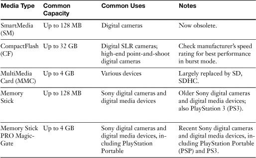
Table 12-9 lists the capacities and typical uses of the most common flash memory card types.
Table 12-9 Flash Memory Card Capacities and Uses
Flash Card Reader
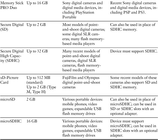
To enable flash memory cards like those shown in Figure 12-25 and Table 12-8 to be used with a computer, use a card reader. Figure 12-26 shows a typical external multislot card reader.
Figure 12-26 A multislot card reader supports a wide variety of flash memory cards.
![]()
Note
Many recent computers incorporate a multislot card reader. Some printers and multifunction devices also include card readers. Some card readers built into printers and multifunction devices are used only for printing, while others can be used to transfer files to and from the host computer.
Most card readers assign a separate drive letter to each slot.
Installing and Using a Flash Card Reader
To install a flash card reader on Windows 2000, XP, or Vista, connect it to an available USB port. The system will automatically detect the reader, assign drive letters as required, and display a notification at the end of the installation process. With older versions of Windows or other operating systems, it might be necessary to install a driver first before connecting the reader.
When you insert a flash memory card containing files, Windows XP/Vista might display an AutoPlay dialog providing various programs that can be used to view or use the files on the card (see Figure 12-27). If AutoPlay does not appear, or with Windows 2000, open My Computer or Windows Explorer and navigate to the appropriate drive letter to use the files on the card.
Figure 12-27 A typical AutoPlay menu displayed when a flash memory card containing photos is inserted into a card reader.

Hot-Swapping Flash Memory Cards
Windows optimizes flash memory cards for quick removal. To safely remove a flash memory card from a card reader, close any Explorer window displaying the card’s contents or navigate to a different folder. Check the status light to make sure the card is not being accessed and then remove the card.
USB Flash Memory Drives
USB flash memory drives have largely replaced floppy drives for transfers of data between systems or for running utility programs. USB flash memory drives, like flash memory cards, use flash memory, a type of memory that retains information without a continuous flow of electricity. However, USB flash memory drives do not require a card reader.
USB flash memory drives are preformatted with the FAT16 or FAT32 file system and are ready to use. Simply plug one into a USB port, and it is immediately assigned a drive letter. You can copy, modify, and delete information on a USB flash memory drive, just as with a hard disk or floppy drive. A typical USB flash memory drive is shown in Figure 12-28.
Figure 12-28 A typical USB flash memory drive with a retractable connector.

![]()
Hot-Swapping USB Flash Memory Drives
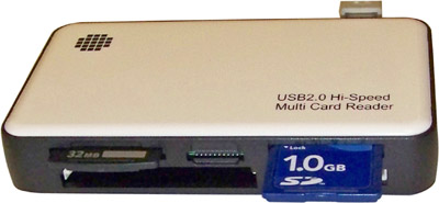
Windows optimizes USB flash memory drives for quick removal; devices optimized for quick removal do not use disk caching. To safely disconnect a USB flash drive from your system, you should make sure no data is being read from or written to the device. To do this, use the Safely Remove Hardware icon in the notification area (systray). Click Safely Remove Hardware to bring up the dialog shown in Figure 12-29. Click the device and click Yes to confirm the selection to remove the device. After Windows displays a dialog indicating that you can remove the device, you can unplug it from your system.
Figure 12-29 Preparing to remove a USB flash memory drive with Safely Remove Hardware.
![]()
Note
Some USB flash memory drives include their own management software. In such cases, use the Eject feature provided with the drive instead of Safely Remove Hardware.
You can also right-click the Safely Remove Hardware icon and click select Safely Remove Hardware to bring up a list of removable devices. From this list, you can see the properties of each device before you stop it.
Caution
If internal SATA hard disks in the list of removable drives support hot-swapping, they will also show up in the Safely Remove Hardware list. Do not select these drives for removal.
External Hard Disks
Most external hard disks connect via the USB or IEEE-1394 ports, but some external SCSI hard disks are also available. External USB or IEEE-1394–based hard disks are preformatted (typically with the FAT32 file system) and are ready to work. Plug in the drive, and it appears in My Computer or Windows Explorer.
Note
If you connect an external drive to a system that does not have appropriate drivers installed, the device cannot be used until drivers are installed. However, Windows XP and Vista include drivers for most external storage devices.
SCSI-based external hard disks must be prepared using a format utility provided with the SCSI host adapter or built into the SCSI host adapter’s BIOS.
External USB hard disks are available in three form factors: 3.5-inch, 2.5-inch, and 1.8-inch. Most USB drives use the larger 3.5-inch or 2.5-inch form factors.
Hard disks using 3.5-inch drive mechanisms require an AC adapter, but offer higher capacities and greater performance than those based on 2.5-inch hard disks.
Hard disks based on 2.5-inch or 1.8-inch drive mechanisms can be powered by the USB port itself, and usually do not need external AC power.
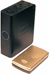
Figure 12-30 compares typical 3.5-inch and 2.5-inch USB hard disks.
Figure 12-30 Typical 3.5-inch (left) and 2.5-inch (right) external USB hard disk drives.
Hot-Swapping USB or IEEE-1394–Based External Hard Disks
Windows optimizes USB and IEEE-1394a external hard disks for performance; that is, disk caching is used to improve system responsiveness. Windows uses a feature sometimes called “lazy writing” to delay writing to the disk. As a consequence, you should never disconnect a USB or IEEE-1394–based hard disk from a system unless you use Safely Remove Hardware to stop the drive.
Troubleshooting Storage
Use the following sections to learn the most common problems affecting storage devices and how to solve them.
Troubleshooting Floppy Disk Drives
Floppy drives are relatively complex devices despite their small storage capacity. Problems can result from incorrect cabling, mechanical drive or media failures, incorrect BIOS configuration, dirt or dust, and interface failures. Use this section to prepare for troubleshooting questions on the A+ Certification Exams as well as your day-to-day work with floppy drives.
Internal Floppy Drive Cabling Problems
Floppy drive data cables that are reversed (pin 1 to pin 33) at either the floppy drive interface on the motherboard/floppy controller card or at the drive itself will cause the drive light to come on and stay on. To correct this, turn off the system, remove and reattach the data cable, and restart the system. Although some floppy drives and cables are keyed to prevent improper insertion of the data cable, others are not.
Floppy drive data or power cables that are not attached to the drive will cause the system to display a floppy drive error when the drive is checked at system startup. Turn off the system, attach the missing cables, and restart the system to correct this problem.
BIOS Configuration Problems
Users must properly configure floppy drives in the BIOS setup program—floppy drives do not support an auto-detect feature. If the system produces a floppy drive error at startup or is unable to format, read, or write disks at the proper capacities, the drive type set in the system BIOS setup program might be inaccurate. Restart the system, start the BIOS setup program, and verify that the correct drive types are set for drive A: and drive B:.
If you can use a USB floppy drive within the Windows GUI, but it is not accessible during boot or Windows installation, the drive might not be configured properly in the system BIOS, or the system might not support USB floppy disk drives.
Drive Reliability and Compatibility Problems
Problems with drives reading and writing media can stem from the following issues:
• Dirty read/write heads— Dirty read/write heads can result from the constant pressure of the drive’s read/write heads on the relatively fragile magnetic surface of the disk and from the constant flow of air being pulled through the system by cooling fans located in the power supply and elsewhere. Dirty heads can cause read and write errors. To clean the drive heads, use a wet-technology head cleaner, which uses a blank disk containing a fabric cleaning disk instead of media and an alcohol-based head cleaner. Insert the disk and spin the drive with a program such as Explorer or Scandisk to clean the heads. Allow the heads to dry for a few minutes, and try the operation again.
• Defective drive mechanisms— Several parts of the floppy drive are subject to failures, including the drive motor, the read/write heads, the head-positioning mechanism, and the shutter-retraction mechanism (3.5-inch drives only).
A floppy drive with a motor that runs too fast or too slow or has misaligned read/write heads will cause a drive to write data that can be read only by that drive. Media from other drives can’t be read on a drive with these defects, and drives with these defects can’t write data that can be read by other drives. Floppy drives with misaligned heads or off-spec drive motors can’t be fixed and must be replaced.
If the head-positioning mechanism fails, data can’t be read or written and the drive will not perform a seek at system startup. The head-positioning mechanism frequently uses a worm-drive mechanism that can be replaced or freed up if stuck.
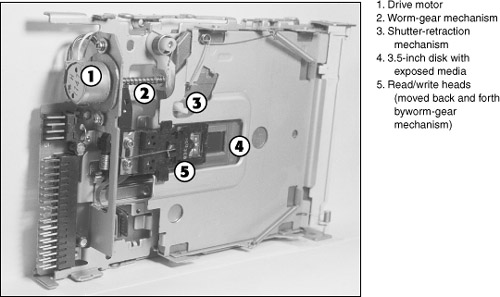
If the shutter-retraction mechanism is jammed, you cannot insert a disk into a 3.5-inch drive. Remove the drive’s top cover so that the drive mechanism is visible, as shown in Figure 12-31, and you should be able to insert the disk. The usual cause is a bent top cover; adjust the cover and replace it.
Figure 12-31 A typical 3.5-inch 1.44MB internal floppy disk drive with its top cover removed.
Note
These repair tips should be used only in emergencies. In most cases, the best solution for a broken floppy drive is a brand new replacement, especially because these drives usually cost about $15.
Figure 12-31 shows the major components of a typical 3.5-inch disk drive. Components include a drive motor; a worm-gear mechanism, which moves read/write heads; and a shutter-retraction mechanism. The drive shown in Figure 12-31 has a 3.5-inch disk inserted; the shutter-retraction mechanism has pushed the shutter to one side so that the media is visible.
Changeline Problems
On 3.5-inch internal floppy drives, pin 34 of the floppy interface senses disk changes and forces the system to reread the disk’s file allocation table and display the content of the new disk when the disk is changed and viewed from a command prompt. This feature is referred to as changeline support.
If the DIR (directory) command displays the same contents for a different disk as for the first disk, changeline support has failed; this problem is also called the phantom directory.
Caution
If this problem isn’t corrected, the computer could trash the contents of the floppy disk because it uses the original disk’s file allocation table to determine where to place files on the new disk.
Because pin 34 uses the last connector on the floppy cable, check to see whether the cable is loose or damaged. If an adapter is being used to convert a tongue and groove floppy cable made for 5.25-inch drives to connect to the pin connector on 3.5-inch drives, remove the adapter and cable and replace the cable with one which has the correct pin connector. (See the next section for further troubleshooting steps.) Note that Windows file/disk management programs such as Windows Explorer and My Computer don’t always automatically detect disk changes; you can press the F5 key to reread the contents of a floppy disk.
To force the system to reread the contents of a floppy disk from a command prompt, press Control+C after inserting a new floppy disk but before you use the DIR command.
Isolating Floppy Subsystem Problems
The floppy disk drive subsystem consists of three parts: the drive, the interface cable and the host adapter (built into the motherboard on most recent systems), along with the BIOS configuration for the drive. The troubleshooting options listed earlier dealt with the most likely causes of particular floppy disk drive problems. However, any part of the subsystem could cause a floppy disk drive problem. If you suspect a hardware failure, follow this procedure:
Step 1. With most floppy disk drive problems, you should exchange the floppy disk drive cable first for a spare that is known to be working. This solves many problems because the cable is inexpensive and easily damaged.
Step 2. Disconnect any tape drive sharing the floppy cable (either on the drive B: connector or with an adapter cable). If the floppy drive works correctly without the tape drive connected to the system, replace the adapter cable for the tape drive if you still need to use the drive. If the tape drive is no longer needed (floppy-interface models are very outdated), remove the tape drive from the system.
Step 3. Replace the drive. Floppy disk drives are also inexpensive and easily damaged; their design no longer permits major repairs.
Step 4. If the problem persists, check the cable and drive on another system. If they check out okay, the floppy disk controller on the motherboard or host adapter card is probably defective. Replace the motherboard or host adapter with a new one.
Troubleshooting PATA (ATA/IDE) Drives
Problems with PATA drives can result from cabling, detection, geometry, physical damage, and jumpering issues. Use this section to prepare for IDE troubleshooting questions on the A+ Certification Exam and in your day-to-day work.
Incompatible PATA Cables
PATA cables that use one keying method (plugged pin 20 or raised projection) cannot be plugged into drives or motherboards that use the other keying method. To correct the problem, replace the cable with a cable that either is not keyed or supports the same keying method as the motherboard and drive.
UDMA-66 or Faster Drive Limited to UDMA-33 Speeds
This error is caused by using a 40-wire cable instead of the 80-wire cable required for UDMA-66, UDMA-100, and UDMA-133 transfer rates. In most cases, changing the cable is all that’s required. With some older drives, you might also need to run the drive vendor’s speed-change utility after you install the 80-wire cable to enable UDMA-66 or faster modes.
No Power to Drive
If the power cable is not plugged into a PATA drive during installation, it will not spin up when the system is turned on—you will not be able to hear the drive running and the system will not detect it. To correct the problem, turn off the system and reattach the power cable.
Cables Attached Incorrectly to ATA/IDE Interface or Drive
User errors in attaching cabling to ATA/IDE interfaces can cause detection problems. Some old 40-wire PATA cables do not use either keying method that is supported by PATA drives, making it easy to reverse either end of the cable or to install the cable over only one row of connectors. If a PATA cable is reversed when it is attached to either the drive or the PATA host adapter, one of two symptoms are typical:
• Many systems will not display any information onscreen when restarted. These systems send a query to the drive and wait to complete the boot process until the drive responds. The drive never gets the message because the cable is attached incorrectly.
• Other systems will display a drive error because the drive cannot be detected during startup.
In both cases, if the power cable is attached to the drive, you will be able to hear the drive spinning as soon as the system is turned on.
The solution in either case is to make sure that the PATA cable’s pin 1 (normally marked by a colored stripe) is attached to pin 1 on both the IDE host adapter (card or motherboard) and the PATA drive and that the cable attaches to both rows of pins on the drive and interface.
Physical or Electronic Damage to Drive
PATA drives can be damaged by shock and impact; don’t drop your drive and expect it not to notice. If the BIOS cannot detect a drive and you already have checked BIOS configuration and cabling, the drive itself might be damaged. PATA drives should operate very quietly. A drive that makes scraping or banging noises when the system is turned on has sustained head or actuator damage and must be repaired or replaced.
If the system fails to start when a drive is attached to a power lead from the power supply, but starts normally when the drive is disconnected from power, the drive’s power connector has a short. You should repair or replace the drive. If the drive is connected to the power supply via an extender or Y-splitter, remove the extender or splitter and connect the drive directly to the power supply; if the system starts, the extender or Y-splitter is defective.
Jumpering Issues
If two PATA drives are attached to a single 40-wire ATA/IDE cable, one drive must be jumpered as master and the other as slave. If both drives are jumpered as master or both as slave, neither drive can be auto-detected by the BIOS or accessed by the system. If the original drive on the cable was working properly until a new drive was installed, check the jumpering on both the original (it should be set to master) and new drive (it should be set to slave).
If an 80-wire cable is being used, both drives can be set to cable select; the cable sets master and slave according to the drives’ positions on the cables.
Some combinations of different brands of drives cannot be used on a single cable even if the jumpering is correct. If you are unable to detect one or both drives when two drives are connected to a single ATA/IDE cable and you have verified the jumpering is correct, the drives might not be fully compatible with ATA standards. Change the master to slave and the slave to master, move the slave drive to the other IDE cable, and rejumper both drives, or use a UDMA-66 cable with cable select settings to enable both drives to work.
Drive Not Ready Error
Some PATA hard drives report “not ready” errors during initial system power-on, but if the system is restarted with a warm boot, the drive runs normally and starts the system. This is caused by a hard drive that has not spun up when the system tries to boot from the drive. To solve this problem, allow the system more time during the boot process to make sure the drive is ready before attempting to boot from it. Use the following methods:
• Adjust the Delay Timer option available in some BIOS programs; this pauses the boot process a few seconds to allow the drive to start.
• Disable the Quick Boot option available in some BIOS programs.
• Allow the system to perform a full memory count and test before booting.
Using Hard Disk Diagnostics
Most hard disk vendors provide diagnostic programs that can be used to test drives for errors. The latest versions of these programs can be obtained from the drive vendors’ websites.
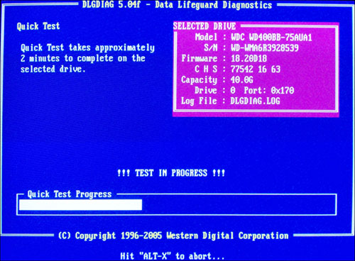
Typically, these programs offer a quick and a long test option. To determine if a hard disk is functioning, run the quick test first (see Figure 12-32). If the drive passes, use the long test to determine if the drive is working within specifications.
Figure 12-32 Performing a quick test on a Western Digital hard disk with vendor-supplied diagnostic software.
![]()
During the long test, defective areas on the drive can be replaced by spare capacity built into the drive. Because defective areas on the disk might not be able to be moved to another location, drive vendors often recommend you perform a full backup before testing a hard disk.
Troubleshooting CD-ROM and DVD Drives
The same problems can occur with CD-ROM and DVD drives as with other drives or devices that use the same interface, but additional problems can occur because these drives use removable optical media. The following are some typical problems:
• Read delays after new media is inserted
• Can’t use a particular drive with a CD/DVD mastering program
• Can’t write to media
• Buffer underrun failures
• Can’t read some media types in CD-ROM or DVD drives
• Damage to media prevents drive from reading media
• Can’t play music through sound card’s speakers
The following sections describe details related to each problem.
Read Delays After New Media Is Inserted
Read delays of several seconds are normal when you insert media into an optical drive; the drive must spin up the media to read it, and delays are sometimes longer with faster drives. Windows XP’s enhanced Autoplay feature reads the contents of the media and by default brings up a list of programs that can be used to access the drive, adding further delays. A delay of more than about 20 seconds can indicate drive or media problems; clean the drive with a cleaning CD, which uses small brushes to wipe debris and dust away from the laser, and try the CD again.
Tip
If the media is not marked, it might have been inserted upside down into the drive. Most blank CDs have a light green reflective surface (some have a gold or blue reflective surface). Blank CD-RW media has a mirror-like reflective surface. Blank DVD media has a blue reflective surface.
Drive Not Supported by CD/DVD Mastering Program
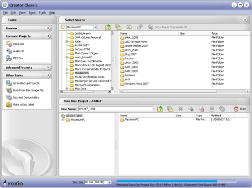
Originally, the only way to write to CD-R media was with a mastering program such as Roxio Media Creator or Nero. These and similar programs typically feature a Windows Explorer–style interface, which you use to create a list of files and folders you want to write to a CD or DVD (see Figure 12-33).
Figure 12-33 Creating a layout for a mastered CD with Roxio Easy Media Creator’s Creator Classic module.
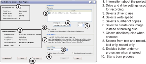
After the layout is created, an additional dialog is used to configure the burn process (see Figure 12.34).
Figure 12-34 The Burn Progress dialog box in Roxio Easy Media Creator’s Creator Classic module.
Although most recent CD and DVD mastering programs support any connected drive, some older CD and DVD programs do not. If your particular brand and model of writeable drive isn’t supported by the mastering program you want to use, you can’t use the program to write to your media.
Here are some indications your mastering program doesn’t work with your drive:
• The program doesn’t detect your drive at all.
• The program doesn’t list your drive as a target drive for writing files.
• When you install the program, it informs you that no compatible CD or DVD drives were found.
• The program detects your drive, but displays an error message when you try to write files to the drive.
To solve problems like these, try
• Downloading the latest CD or DVD recorder support files from the vendor’s website— Some vendors provide a database of supported recorders and software versions you can query. If your recorder appears on the list of supported recorders, but the version of software listed is more recent than the one you use, download the recommended update. Keep checking the software vendor’s website for further updates if your recorder isn’t listed yet.
• Upgrading to the latest version of your preferred software— If you use a no-longer-current version of CD-mastering software and your recorder isn’t listed as supported, see if the latest version will support it and purchase the upgrade if a free update isn’t available.
• Using the recording software provided with the drive instead of a third-party product— Although many writeable drives come with bare-bones software that might lack the features of a commercial product, the program packaged with the drive will work.
• Changing to a different CD/DVD mastering program— If the latest version of your preferred program does not support your drive, switch to a different program.
Can’t Write to Media
Problems writing to media can be caused by
• Incompatible media
• Closed media
• Packet-writing problems
• Media problems
• Incorrect insertion of media
Although current Super Multi DVD drives support all recordable and rewritable CD and DVD media, older drives might not support some media types. For example, drives that support only DVD-R/RW media will not work with DVD+R/RW media; drives designed for single-layer DVD media cannot write to dual-layer (DL) media.
All but the earliest CD-ROM drives are designed to read media that can be added to (multiple session) or media that has been closed (write-protected).
If your CD or DVD-mastering program displays an error message indicating that you need to insert media that has enough room for the files you want to write, and the media has more than enough space, the media was closed when it was created, and no more files can be placed on the media. You can determine how much space is used on a writeable CD or DVD with Windows Explorer/My Computer. Right-click on the drive and select Properties to see the amount of space used. 74-minute media can hold about 650MB, whereas 80-minute media can hold about 700MB of information; single-layer DVDs can hold about 4.7GB of information, whereas dual-layer DVD can store about 8.5GB of information. The Properties sheet will also say the media has 0 bytes free, but this is misleading. Most mastering programs will also list the amount of space used by the files you want to transfer to CD or DVD.
Tip
If you want to write files to the media more than once, be sure that you select the option that doesn’t close (finalize) the media when you create the disc. Some programs choose this option for you by default, whereas others might close (finalize) the disc unless you choose otherwise. If you are writing to a DVD-RW disc, you might need to unfinalize (open) the media before you can add additional files.
CD/DVD mastering is an excellent way to copy a large number of files to a CD or DVD all at once, but it’s not designed to enable files to be dragged from their original location and dropped (copied) to a disc. Hence, most CD- and DVD-mastering programs include separate packet-writing programs to enable drag-and-drop file copying. For example, Easy Media Creator includes Drag and Drop, and Nero includes InCD (or you can download a copy if your version of Nero doesn’t include it). Packet-writing software writes files that correspond to a standard called Universal Disk Format (UDF); UDF is also used by the Windows Live File System format used by Windows Vista’s built-in DVD recorder support.
Floppy disks, Zip disks, SuperDisks (LS-120/LS-240), and other types of magnetic removable-media storage are preformatted; you can copy files to them as soon as you insert them into the drive. However, optical media must be formatted before you can use it for drag-and-drop copying.
The packet-writing software supplied with your drive (or as part of a CD/DVD-creation program you purchased) is used to perform this task. After you start the program, insert your media and click the Format button (see Figure 12-35).
Figure 12-35 The Roxio Drag-to-Disc formatting program preparing a blank CD-RW disc for use.
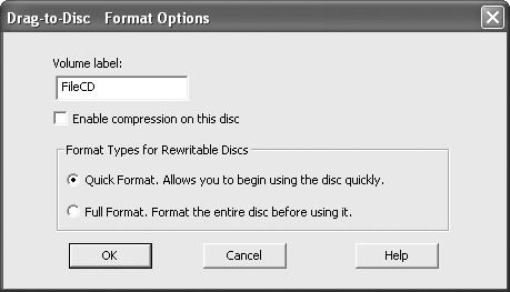
You should provide a label (descriptive name) for your media to make it easy to distinguish between different discs. (The label is displayed in Windows Explorer/My Computer.) Use compression to save space.
If you are unable to start the formatting process, check the following:
• If you have another writeable drive installed, close any resident software used by the other drive (check the system tray).
• Use the correct type of media for your recorder and packet-writing program.
No matter what type of media you use, make sure you insert it correctly. The unlabeled side faces towards the tray.
Can’t Read Some Media Types in CD-ROM or DVD Drives
Older CD-ROM drives (generally those under 24X speed) and first-generation DVD drives are unable to read CD-RW media, which has a lower reflectivity than CD-ROM or CD-R media. Newer DVD drives and virtually all CD-ROM drives at 24X or faster speeds use a modified laser to enable them to read CD-RW media.
CD-ROM drives that can read CD-RW media are sometimes called MultiRead drives. DVD drives that can read CD-RW and different types of DVD media are called MultiRead2 drives. To determine if a drive can read a specified type of media, check its specification sheet. Older drives that lack CD-RW compatibility cannot be upgraded—they must be replaced.
If the drive is MultiRead- or MultiRead2-compliant but you can’t read the media, install the UDF reader provided by the vendor whose software was used to create the disc. Some UDF reader software is copied to the rewritable CD or DVD for installation on the target PC, whereas others require you to download the reader and install it manually.
Because rewritable CD/DVD support can be spotty, it’s best to use recordable media (CD-R, DVD-R, or DVD+R) recorded with a mastering program to distribute files to other users.
Buffer Underrun Failures
Ever since the first recordable CD drive was introduced, users have created untold numbers of useless coasters because of buffer underruns. A buffer underrun takes place when the writeable CD or DVD drive transfers data to the disc faster than the computer can provide it to the drive. Because the flow of data is interrupted, the recording stops and the media is useless.
All current writeable CD and DVD drives include some type of buffer underrun–prevention technologies such as BURN-Proof, SmartBurn, and others. These technologies work by suspending the CD creation process whenever the buffer memory in the CD runs out of information and continuing the process when more data is available. Upgrading from a drive that lacks this feature to a drive that supports this feature is the easiest way to avoid buffer underruns and enjoy much faster disc creation times.
Here are some other ways to avoid creating a coaster with your drive (refer to Figure 12-34 for examples):
• If your drive supports buffer-underrun prevention, make sure your CD-mastering software also supports this feature and make sure you leave it enabled.
• If your CD-mastering software offers a Test option, use it to simulate CD recording at various speeds. If the program reports an error at the highest recording speed, reduce the speed and try the test again.
• Upgrade the firmware in the drive to the latest version.
Damage to Media Prevents Drive from Reading Media
Because all types of optical drives read data recorded in a single spiral track, fingerprints or surface damage to the clear protective layer over the media surface will prevent data beneath the dirty or damaged surface from being read. A cracked or severely scratched optical disc cannot be read at all.
Dirty optical discs can be cleaned with the same cleaners used for music CDs. Some surface scratches can be polished away with special repair kits available from computer and music stores, and special protective shields can be attached to the nonlabel (data) side of frequently used optical discs to protect the media. Media should be stored in a protective sleeve or jewel case when not in use.
Can’t Play Music Through Sound Card’s Speakers
Many users like to use their computers as stereo systems, taking advantage of their optical drives and sound card hardware to play music in their homes or offices. If the user is unable to hear CDs being played through the CD player software supplied on most systems, check the following:
• CD audio cable— If your digital media software cannot play music via the PATA or SATA interface, connect a two-wire (digital) or four-wire (analog) music cable between your optical drive and the correct jack on the sound card or motherboard audio.
• Windows sound mixer controls— In most cases, a speaker icon will be visible in the Windows system tray when sound hardware is installed. Click the speaker icon to display the mixer control. If the volume for CD audio is turned down to minimum or is muted, or if all audio is muted, no sound will be audible. Enable the sound and adjust the volume to hear music.
• Volume control in CD player application— The volume control in the player program might be set too low if the sound is not audible after checking the first two items. Adjust it as required.
Troubleshooting Removable-Media, External, and Tape Drives
Typical problems with removable-media, external, and tape drives include
Use the following sections to learn how to troubleshoot these drives.
Drive Not Recognized Problems
Removable-media drives plugged into PnP interfaces such as IEEE-1394 and USB 1.1/2.0 should be recognized by the system as soon as they are connected to the appropriate port. If they are not recognized, check the following:
• Make sure the interface has been enabled and its drivers loaded. If the interface is not enabled, any devices using it can’t be detected. See Chapter 7, “I/O and Multimedia Ports and Devices,” for details.
• Install drivers and utility software before connecting the drive. This helps the system to better recognize the drive.
• If the tape drive isn’t recognized by tape backup software, verify the drive is supported by the software. If not, update the software or use compatible software. You might also need to install drivers provided by the backup vendor for your drives in place of the normal Windows drivers; check with the backup software vendor for details. Note that Windows Vista’s backup program does not support tape drives; you must use third-party backup software to enable tape backups with Windows Vista.
• Check cable connections between the port and the drive. If the cables are loose, reattach the cables. If the cables are bad, use approved replacements. Note that some vendors recommend that only the cables shipped with the drive be used.
• If the drive is bus powered, verify that the USB or IEEE-1394 port has enough power to run the drive. Bus-powered USB hubs or daisy-chain connections on IEEE-1394 devices might not provide enough power to run the drive. Connect the drive directly to a port on the PC and try again, or connect an AC adapter to the drive if available.
• Verify that other devices plugged into USB or IEEE-1394 ports are working. If no other devices are working, the port might have failed. Check the Windows Device Manager for the port status and power level available for each USB port.
Note
Some vendors of portable (2.5-inch based) USB hard disk drives provide, or sell as an option, a Y-shaped USB cable that draws power from two USB ports. Use this cable if you are unable to run the drive from the power available from a single USB port.
If the removable-media drive is plugged into a SCSI host adapter, check the following:
• Inspect terminator settings. A drive or device at the end of the SCSI daisy-chain should be terminated; other drives/devices should not be terminated.
• Verify the drive has a unique device ID.
• Make sure an external SCSI drive is turned on before the system is turned on.
• Make sure the drive is properly connected to the data cable; an internal drive also needs to be connected to a power lead from the power supply.
If the removable-media drive is plugged into a PATA host adapter, check the following:
• Drive jumpers should be set to a unique setting (master or slave) if a 40-wire cable is used. If the existing drive is master, the removable-media drive must be jumpered to slave. If an 80-wire cable is used, both the existing drive and new removable-media drive can be jumpered as cable select.
• Make sure the drive is properly connected to the data and power cables.
Read/Write Problems
Read/write problems with removable-media drives can involve problems with the media or with the drives themselves. Check the following:
• Try the media in another drive. If the media can be read or written to in another drive, the first drive you tried is defective.
• Make sure the media isn’t write protected. SuperDisk, 3.5-inch floppy disks, SD, and SDHD media use mechanical sliders to write-protect the media’s contents, but most other types use write protection configured by the drive’s utility software. Tape drives might use mechanical or software write protection.
• Use an approved cleaning disk or cartridge made especially for the drive. Check with the drive vendor for recommended models, and don’t use other types.
• Double check power and data cable connections to the drive.
• Download and install the latest drivers and utilities for the drive; run diagnostic software provided by the vendor to pinpoint problems.
• If the drive makes unusual noises, it could indicate damage to the drive heads or media. Contact the vendor immediately for help, and don’t use media containing valuable data until you determine if the disk cartridge or drive itself has failed.
• Re-tension tapes before reading or writing.
Exam Preparation Tasks
Review All the Key Topics
Review the most important topics in the chapter, noted with the key topics icon in the outer margin of the page. Table 12-9 lists a reference of these key topics and the page numbers on which each is found.
Table 12-10 Key Topics for Chapter 12

Complete the Tables and Lists from Memory
Print a copy of Appendix B, “Memory Tables,” (found on the CD), or at least the section for this chapter, and complete the tables and lists from memory. Appendix C, “Memory Tables Answer Key,” also on the CD, includes completed tables and lists to check your work.
Definitions of Key Terms
Define the following key terms from this chapter, and check your answers in the glossary.
FDD,
HDD,
PATA,
IDE,
SATA,
PIO,
UDMA,
Troubleshooting Scenario
You are working on a computer. You plug up your external hard drive and for some reason it does not show up in the Explorer window. You then happen to notice that this computer is actually running a server-based operating system. What would be the steps you need to take to fix this problem?