

104 Chapter 4: QoS Support on the Catalyst 5000 Family of Switches
Classification and Marking
The Catalyst 5000 Family of switches bases classification solely on Layer 2 CoS values.
Although the switch can rewrite Layer 3 IP precedence values in specific configurations,
the switch does not use ToS values, including IP precedence values or DSCP values to make
any QoS classification, marking, or congestion avoidance decisions. With regard to classi-
fication, the Catalyst 5000 Family of switches is similar to the Catalyst 4000 CatOS Family
of switches and the Catalyst 2900XL and 3500XL switches.
Classification and Marking of Untagged Frames Based on Ingress Port
The Catalyst 5000 switch does not support any port-level rewriting of DSCP or ToS values,
the switch only rewrites the ingress frames’ CoS value and does not alter the DSCP or ToS
bits even on untrusted ports. In this respect, the Catalyst 5000 Family of switches, by
default, does not trust CoS values but always trusts DSCP or ToS values. Nevertheless, the
Catalyst 5000 Family of switches can reclassify and mark untagged frames with a specific
CoS value similar to the Catalyst 2900XL and 3500XL switches on line modules that
support QoS features as indicated in Table 4-2. The switch must transmit the frame with a
dot1q tag or Inter-Switch Link (ISL) header for the respective CoS value to be present on
egress. Use the following command to configure a port to classify untagged ingress frames
with a specific CoS value:
set port qos
mod/ports
cos
cos_value
cos_value represents the overriding CoS value. To clear the configuration, use the clear
port qos {mod/ports} cos command. Example 4-7 illustrates a user configuring a switch
port to classify untagged ingress frames with a specific CoS value and then clearing the
configuration.
No options exist on the Catalyst 5000 Family of switches for trusting CoS, trusting DSCP,
or trusting IP precedence.
Classification of Tagged Frames Based on Ingress Port
The Catalyst 5000 Family of switches trusts ISL- or dot1q-tagged frames’ CoS value by
default and does not support reclassification or marking of tagged frames based on port
configuration.
Example 4-7 User Configuring Port to Classify Untagged Frames with Specific CoS Value
Console> (enable) ss
ss
ee
ee
tt
tt
pp
pp
oo
oo
rr
rr
tt
tt
qq
qq
oo
oo
ss
ss
33
33
//
//
11
11
cc
cc
oo
oo
ss
ss
55
55
Port 3/1 qos cos set to 5
Console> (enable) clear port qos 3/1 cos
Port 3/1 qos cos setting cleared.
Classification and Marking 105
Classification and Marking Based on Destination VLAN and MAC
The Catalyst 5000 Family of switches supports rewriting the CoS value of selected desti-
nation MAC address on a VLAN basis. For a CoS value to be present on the egress frame,
the switch must transmit the frame with a dot1q tag or ISL header on a port configured for
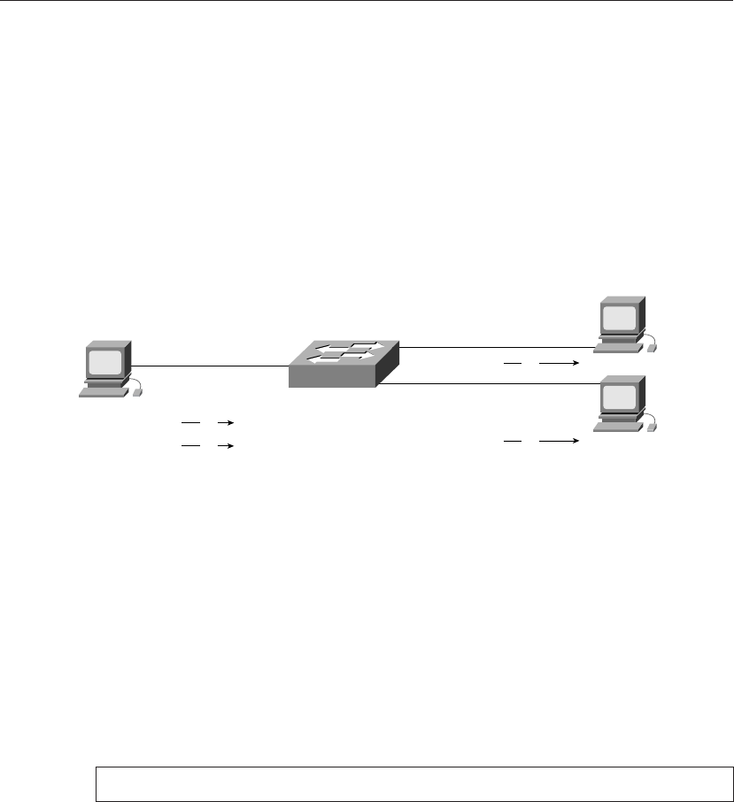
trunking. Figure 4-2 illustrates an example of using classification and marking based on
destination VLAN and MAC. In this example, a Workstation 1 is sending traffic to Worksta-
tions 2 and 3 with a CoS value of 0. The configuration applied to the switch marks traffic
destined for MAC address 0001.4200.0005 with a CoS value of 5. The marking subse-
quently also effects output scheduling for the frames.
Figure 4-2 Topology Illustrating Classification and Marking Based on Destination MAC Address and VLAN
Use the following command to configure marking based on a destination MAC address on
a VLAN basis:
set qos mac-cos
dest_MAC_addr VLAN cos_value
The parameters for this command are defined as follows:
• dest_MAC_addr represents the destination MAC address.
• VLAN represents the VLAN ID where the destination MAC address resides.
• cos_value symbolizes the CoS value to write on the frame.
Example 4-8 illustrates a user configuring classification and marking based on the desti-
nation MAC address using the topology in Figure 4-2.
Classification and marking based on destination MAC address and VLAN does not scale in
large topologies and requires knowledge and continuous updates to MAC addresses. The
preferable methods of classification and marking are to utilize ingress port configuration or
ACEs. The next section discusses classification and marking based on ACEs.
Example 4-8 User Configuring Classification and Marking Based on the Destination MAC Address and VLAN
Console> (enable) ss
ss
ee
ee
tt
tt
qq
qq
oo
oo
ss
ss
mm
mm
aa
aa
cc
cc
--
--
cc
cc
oo
oo
ss
ss
00
00
00
00
--
--
00
00
11
11
--
--
44
44
22
22
--
--
00
00
00
00
--
--
00
00
00
00
--
--
00
00
55
55
55
55
44
44
CoS 4 is assigned to 00-01-42-00-00-05 vlan 5.
Catalyst 5500 with
NFFCII
Workstation 1
Trunk
Trunk
Trunk
0001.4200.0001
0001.4200.0004
0001.4200.0005
Workstation 2
Workstation 3
CoS 0 A
CoS 0 B
CoS 0 A
CoS 5 B
106 Chapter 4: QoS Support on the Catalyst 5000 Family of Switches
Classification and Marking Based on ACE
Classification and marking based on ACE provides a method of classifying and marking IP
version 4 traffic for traffic crossing a routed boundary. Traffic crossing a routed boundary
always passes through a router or switch capable of routing in hardware. The Catalyst 5000
Family of switches may use an RSFC or RSM for this functionality; however, any IP router
supporting MLS is sufficient. Classification and marking based on ACEs supports the
following ACE options:
• IP source address(es)
• IP destination address(es)
• UDP, TCP, or both protocols
• TCP/UDP source port(s)
• TCP/UDP destination port(s)
When ACE-based classification occurs, the switch marks the IP precedence bits in the IP
header to match the CoS value. This behavior differs completely from newer platforms,
such as the Catalyst 4000 IOS Family of switches. Later chapters discuss the differences in
classification and marking behavior of the newer platforms. In addition, ACE-based
marking rewrites CoS values written by the ingress port configuration or the destination and
VLAN-based classification and marking configuration. CoS-to-IP precedence mapping or
any other mapping table is not configurable.
Furthermore, classification and marking based on ACE behaves differently depending on
the MLS configuration. In brief, without MLS enabled, the switch carries out ACE-based
classification on all traffic. With MLS enabled, the switch executes ACE-based classifi-
cation only on MLS-switched traffic. The following sections provide more details on this
subject.
MLS Fundamentals
As discussed in the “Catalyst 5000 Family of Switches QoS Architectural Overview”
section of this chapter, enabling MLS allows the supervisor engine to perform Layer 2
rewrites of routed packets. Layer 2 rewrites include rewriting the source and destination
MAC addresses and writing a recalculated cyclic redundancy check (CRC). Because the
source and destination MAC address changes during Layer 3 rewrites, the switch must
recalculate the CRC for these new MAC addresses. The switch learns Layer 2 rewrite infor-
mation from the MLS router via an MLS protocol. Figure 4-3 illustrates the fundamentals
behind MLS.

Classification and Marking 107
Figure 4-3 Logical Representation of Creating MLS Flow
In Figure 4-3, when Workstation A sends a packet to Workstation B, Workstation A sends
the packet to its default gateway. In Figure 4-3, the default gateway is the RSM. The switch
(MLS-SE) recognizes this packet as an MLS candidate packet because the destination
MAC address matches the MAC address of the MLS router (MLS-RP). As a result, the
switch creates a candidate entry for this flow. Next, the router accepts the packets from
Workstation A, rewrites the Layer 2 destination MAC address and CRC, and forwards the
packet to Workstation B. The switch refers to the routed packet from the RSM as the enabler
packet. The switch, upon seeing both the candidate and enabler packets, creates an MLS
entry in hardware so that the switch rewrites and forwards all future packets matching this
flow. The MLS Switched Packet arrow in Figure 4-3 indicates this flow. For more details
and examples on the MLS architecture, consult the following technical document at
Cisco.com:
“Troubleshooting IP MultiLayer Switching” Document ID: 10554
When using the MLS feature on the Catalyst 5000 Family of switches in conjunction with
QoS classification and marking based on ACEs, classification and marking only occurs on
MLS-switched packets. This limitation presents the following important caveats.
• MLS-RP must see both the candidate and enabler packets to create a flow.
• Candidate and enabler packets are not subject to classification or marking based on ACEs.
• The switch removes MLS entries when the MAC Aging-time expires; therefore, flows
must be symmetrical.
• Packets with a destination network via a WAN port adapter on an RSM module are
not subject to classification and marking based on ACEs.
Catalyst 5500 Switch
with NFFC II
(3) MLS Switched Packet
Workstation BWorkstation A
VLAN 1 VLAN 2
RSM
VLAN 1 VLAN 2
(1)
Candidate
Packet
(2)
Enabler
Packet

108 Chapter 4: QoS Support on the Catalyst 5000 Family of Switches
• MLS ages entries based on an absolute timer; when flows age, the switch must relearn
the entries via the candidate and enabler packets.
• IP routing table changes cause all MLS entries to purge.
As a result of these limitations, a QoS implementation with ACE-based marking and MLS
enabled commonly yields packets without the ACE-based classification and marking. For
networks requiring strict application of ACE-based classification and marking, disable
MLS. Disabling MLS may have side effects, such as a higher CPU utilization on the MLS-
RP. As a result, disabling MLS needs careful consideration and planning.
Configuring ACE-Based Classification and Marking
The switch determines which packets are destined for a router by the destination MAC
address. As a result, the switch requires knowledge of the destination MAC of the router
before any ACE-based classification and marking occurs. Use the following commands to
configure and verify the destination router MAC for ACE-based classification and marking,
respectively:
set qos router-mac
MAC_addr
vlan
show qos router-mac [
MAC_addr
|
vlan
]
Configure multiple router MAC addresses for ACE-based classification and marking on
multiple VLANs or routers. Example 4-9 illustrates a user configuring and verifying a
Catalyst 5000 switch for the router MAC address on multiple VLANs.
ACEs used for classification and marking utilize several options. Use the following config-
uration command to configure an ACE based solely on source and destination IP address
and mask:
set qos ip-filter
cos src_IP_addr_spec dest_IP_addr_spec
cos represents the CoS value that the switch writes to frames matching the ACE.
src_IP_addr_spec represents the source IP address(es) and mask of the ACE, whereas
dest_IP_addr_spec represents the destination IP address(es) and mask. The keyword any
is optional for specifying all IP addresses, and the keyword host represents an IP address
for a single entry, (that is, 255.255.255.255 mask). Enter the host keyword before entering
Example 4-9 User Configuring and Verifying Router MAC Address for MLS
Console> (enable) ss
ss
ee
ee
tt
tt
qq
qq
oo
oo
ss
ss
rr
rr
oo
oo
uu
uu
tt
tt
ee
ee
rr
rr
--
--
mm
mm
aa
aa
cc
cc
00
00
00
00
--
--
33
33
00
00
--
--
ff
ff
22
22
--
--
cc
cc
88
88
--
--
88
88
ee
ee
--
--
dd
dd
cc
cc
44
44
Router MAC/Vlan is set for QoS.
Console> (enable) set qos router-mac 00-30-f2-c8-8e-dc 5
Router MAC/Vlan is set for QoS.
Console> (enable) show qos router-mac
Number MAC address Vlan #
---------------------------------
1 00-30-f2-c8-8e-dc 4
2 00-30-f2-c8-8e-dc 5
..................Content has been hidden....................
You can't read the all page of ebook, please click here login for view all page.