

300 Chapter 8: QoS Support on the Catalyst 6500
Policing
Policing is another feature available on the Catalyst 6500. Policing enables the adminis-
trator to control bandwidth utilization for certain applications. This guarantees the
necessary bandwidth for voice and video and other mission-critical applications. Policing
is performed in hardware on the PFC without impacting switch performance. Policing
cannot occur on the 6500 platform without a PFC and is currently only supported for
ingress traffic. The PFC version within the platform determines the extent of the policing
functionality. The Catalyst 6500 offers both single-rate and two-rate policing.
The purpose of this section is to explain policing operation, as it pertains to the Catalyst
6500. It includes a discussion of microflow and aggregate policers, single-rate policing on
the PFC1 and PFC2, and two-rate policing on the PFC2. Finally, the section includes
numerous configuration examples and various show commands used to verify operation.
Microflow and Aggregate Policers
Two types of policers are available on the Catalyst 6500: microflow and aggregate policers.
Microflow policers limit the bandwidth consumed by individual flows on a port-by-port or
interface basis. A flow is very specific and can be defined using Layer 3 source and desti-
nation addresses, Layer 4 protocol type, and Layer 4 source and destination port numbers.
The bandwidth limitation is applied to each flow matching the criteria defined in the ACLs
separately. The Catalyst 6500 can support up to 63 microflow policers.
Aggregate policers limit an aggregate of individual flows across multiple ports or inter-
faces, or on a single port or interface, to one specified rate. The shared aggregate policer
polices all traffic to a configured rate for all ports to which the policer is applied. On the
other hand, the interface aggregate policer polices all flows for each individual interface.
Up to 1023 aggregate policers can be defined on the Catalyst 6500.
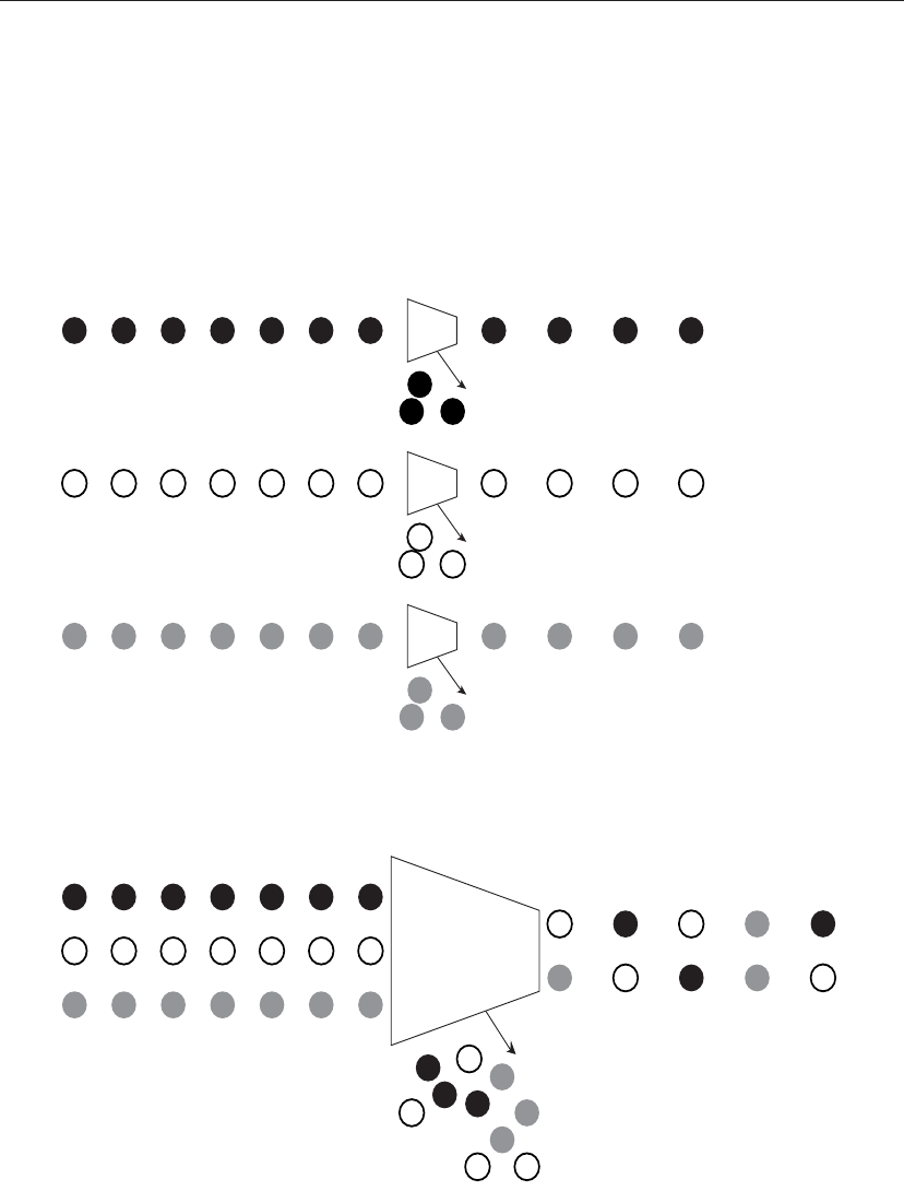
Consider the following example. Assume there is a microflow policer defined limiting the
bandwidth consumption for certain IPTV streams to 1.5 Mbps. After the policer has been
defined, it is applied to the appropriate interfaces, in this case ports 5/1 and 5/3. In this case,
d1 : d2 0 1 2 3 4 5 6 7 8 9
-------------------------------------
0 : 00 01 02 03 04 05 06 07 08 09
1 : 10 11 12 13 14 15 16 17 18 19
2 : 20 21 22 23 00 25 26 27 28 29
3 : 30 31 32 33 34 35 36 37 38 39
4 : 40 41 42 43 44 45 46 47 48 49
5 : 50 51 52 53 54 55 56 57 58 59
6 : 60 61 62 63
(text omitted)
Example 8-30 Modifying the Policed DSCP Mark-Down Table in Native Mode (Continued)
Policing 301
although one microflow policer has been defined and applied to the two separate ports, all
IPTV traffic matching the configured criteria is limited to 1.5 Mbps per flow. Therefore, if
one flow exists on port 5/1 and two flows exist on port 5/3, each flow is limited to 1.5 Mbps,
for a combined total of 4.5 Mbps. Aggregate policers differ slightly. Consider the same
situation, but now the configured policer is an aggregate policer. In this case, the combined
inbound flows for port 5/1 and port 5/3 are considered and allocated a total of 1.5 Mbps.
Any traffic exceeding this rate is classified as nonconforming and subsequently policed.
Figure 8-8 Microflow Versus Aggregate Policer
Discard
Policer
Discard
Policer
Discard
Policer
Microflow Policing
Discard
Aggregate Policing
Policer

302 Chapter 8: QoS Support on the Catalyst 6500
By default, microflow policing only impacts routed traffic. To police bridged traffic, set qos
bridged-microflow-policing enable {VLAN} must be configured in Hybrid mode. The
equivalent command for policing bridged traffic in Cisco IOS is mls qos bridged, which is
configured under the VLAN interface.
Single-Rate Policing
Single-rate policing is supported with the PFC1 starting with Release 5.3(1) for Hybrid
mode and Release 12.0(7)XE for Native mode. Release 6.1(1) for Hybrid mode and
12.1(5c)EX, and 12.1(8a)E for Native mode, introduced support for the PFC2. This is
notable because the PFC2 incorporates an ASIC, allowing policing to occur at dual rates.
The PFC2 offers the excess rate and burst configuration options as an additional
enhancement. As a result, single-rate microflow and aggregate and two-rate aggregate
policing are supported on the PFC2 with these minimum versions of code. This section focuses
on the operation and configuration of the single-rate policer for Hybrid and Native modes.
The policing function on the Catalyst 6500 controls the data after it has completely entered a
port and resides in the packet buffer. When the data arrives, it is compared to the QoS ACL
entries configured. If the data stream matches an ACL entry that is mapped to a policer, the
policer allocates one token for every data bit in the payload of the IP and IPX packets entering
the switch. Sequentially, the policing function occurs after the internal DSCP value has been
derived for the respective frame. If the data is not IP or IPX, the entire Layer 2 frame, as seen on
the D-bus, is used by the policing counter. This includes the source and destination MAC
addresses, as well as Layer 2 encapsulation, including packet padding and cyclic redundancy
check (CRC) information. ISL and 802.1q encapsulation information is excluded. The size of
the frame is important to consider when configuring the burst size. Ensure that enough tokens
are available in the token bucket to sustain the maximum-sized frame processed by the policer.
NOTE The ACLs for the policers are defined in the same manner as previously outlined. However, it
is important to remember the effects the various trust keywords have on deriving the internal
DSCP value. The trust keywords impact any policies defined in the policed DSCP tables.
After the switch has determined that the arriving frame meets the criteria defined in the QoS ACL,
the next step is to establish whether the frame conforms or violates the configured contract. When
configuring the policer, the administrator defines the type, name, rate, and burst depth.
The refresh interval, on the other hand, is already defined and fixed for the Catalyst 6500.
The token bucket is refreshed every .25 ms, which equates to 4000 updates every second.
The number of tokens placed into the token bucket during every interval depends on the
configured contract rate. If enough tokens are present in the token bucket to accommodate
an arriving frame, the data is considered conforming. As a result, no action is imposed on
Policing 303
the frame, which is then forwarded to the egress port or interface. Because the frame was
in profile, the policer is also charged the appropriate amount of tokens, equal to the size of
the transmitted frame in bytes. If either policer, microflow or aggregate, determines a frame
is out of profile, that frame is marked down or dropped according to the policy configured
for that specific policer. If only a microflow policer is configured, the out-of-profile action
is derived from the microflow policy. If only an aggregate policer is utilized, it specifies the
out-of-profile action. If both policer types are defined, the most stringent decision is the one
applied. The following list summarizes these rules:
• If the microflow policer returns an out-of-profile decision, mark or drop according to
the microflow policing rule.
• If the aggregate policer returns an out-of-profile decision, mark or drop according to
the aggregate policing rule.
• If either policer returns an out-of-profile decision, mark or drop according to the
policing rule of the policer that returned the out-of-profile decision.
If both policers return an out-of-profile decision and the rule of either one is to drop, the
packet is discarded; otherwise the packet is marked down and transmitted. The new DSCP
value is taken from the policed DSCP mapping table. By default, frames are not marked
down. They are mapped to the equivalent value. However, values can be modified by the
administrator, and customized to meet specific network requirements. As demonstrated
earlier, the mapping table is applied globally to the switch. For further information, refer to
the section on mapping. Neither the microflow nor the aggregate policer is charged for the
packet if either one returns a policing decision.
A Theoretical Example of Policing Behavior
As discussed, tokens in the token bucket are replenished at a regular fixed interval. The rate
at which tokens are placed into the bucket is once every .25 ms. As a result, every second
has 4000 refresh intervals. During every .25-ms interval, (.00025(s) * rate(bps)) tokens are
placed into the bucket. If 10 Mbps is the configured rate, 2500 tokens are placed into the
token bucket every .25 ms, assuming tokens need to be replaced. All tokens exceeding the
capacity of the bucket are discarded. When selecting a burst size, it is important to ensure
it is configured to be equal to or higher than the desired policing rate.
If you set the rate to 10 Mbps, an acceptable bucket depth, based solely on rate, is as follows:
10,000,000 (bps) * .25 (ms) = 2500, which you would round up to 3 kb
However, packets that are transmitted through the network are never fixed in size; instead,
they vary in length. The possibility exists that a maximum frame size (1518 bytes) can
occur at any interval. Therefore, the burst size must be at least equal to the average or largest
packet size. Consider the following example to demonstrate the behavior of the policer.
In this scenario
Time = .25 ms; therefore the following example represents 10 refresh cycles.

304 Chapter 8: QoS Support on the Catalyst 6500
Assume there is a 100-Mbps interface, and the intent is to police all ingress traffic for the
port down to 10 Mbps, and drop all traffic in excess of this rate. The bucket starts at full
capacity, and the bucket depth is configured to 13 kb, which accounts for large packets
arriving on the interface (1518 * 8 = 12144; rounded = 13000). This results in the following
configuration:
ss
ss
ee
ee
tt
tt
qq
qq
oo
oo
ss
ss
pp
pp
oo
oo
ll
ll
ii
ii
cc
cc
ee
ee
rr
rr
aa
aa
gg
gg
gg
gg
rr
rr
ee
ee
gg
gg
aa
aa
tt
tt
ee
ee
TT
TT
ee
ee
ss
ss
tt
tt
rr
rr
aa
aa
tt
tt
ee
ee
11
11
00
00
00
00
00
00
00
00
bb
bb
uu
uu
rr
rr
ss
ss
tt
tt
11
11
33
33
dd
dd
rr
rr
oo
oo
pp
pp
or
mm
mm
ll
ll
ss
ss
qq
qq
oo
oo
ss
ss
aa
aa
gg
gg
gg
gg
rr
rr
ee
ee
gg
gg
aa
aa
tt
tt
ee
ee
--
--
pp
pp
oo
oo
ll
ll
ii
ii
cc
cc
ee
ee
rr
rr
TT
TT
ee
ee
ss
ss
tt
tt
11
11
00
00
00
00
00
00
00
00
00
00
00
00
00
00
11
11
66
66
22
22
55
55
vv
vv
ii
ii
oo
oo
ll
ll
aa
aa
tt
tt
ee
ee
--
--
aa
aa
cc
cc
tt
tt
ii
ii
oo
oo
nn
nn
dd
dd
rr
rr
oo
oo
pp
pp
*Note No tokens are added at t=1 because the token bucket is at full capacity.
Due to the flow-control mechanisms utilized by TCP, the burst parameter setting based on
the calculation demonstrated in the example is too low. The result is a “sawtooth” effect
seen when TCP attempts to achieve line rate. The policer throttles the TCP stream by
dropping frames, causing TCP to initialize its slow start mechanism. As a result, the average
rate achieved by the TCP session is considerably lower than the configured rate for the
policer. Therefore, when policing TCP streams, as an initial step, it is recommended to
double the burst parameter (2 * burst) to effectively police at the configured rate. As
described section “Burst Size” in Chapter 7, “Advanced QoS Features Available on the
Catalyst 4000 IOS Family of Switches and the Catalyst G-L3 Family of Switches,” if the
round-trip time is known for a particular TCP stream, that value can be used to determine
a burst value. Therefore, the preceding formula can be substituted with (2 * RTT * rate) to
determine a baseline burst value. However, it is important to consider that policing is not
Table 8-14 Operation of Aggregate Policer
Time
Packet
Size
(Bytes)
Tokens
Added*
Token
Bucket
Size (Bits)
Tokens
Removed
(Bits)
Final
Bucket
Size
0 0 0 13000 0 13000
1 751 0 13000 6008 6992
2 600 2500 9492 4800 4692
3 950 2500 7192 0 7192 <--policed
At t=3 No tokens are removed from the bucket, because there are not enough tokens to
handle the entire packet. As a result, a packet arriving at t=3 is dropped due to policing.
4 700 2500 9692 5600 4092
5 830 2500 6592 0 6592 <--policed
At t=5 the ingress packet is dropped due to policing.
6 1050 2500 9092 8400 692
7 450 2500 3192 0 3192 <--policed
8 675 2500 5692 5400 292
9 350 2500 2792 0 2792 <--policed
10 725 2500 5292 0 5292 <--policed
..................Content has been hidden....................
You can't read the all page of ebook, please click here login for view all page.