
In this recipe we will create a spaceship hull material, adding also random light windows and the spaceship's name logo as if painted in red on the hull itself:

- Start Blender and switch to the Cycles Render engine. Select the default cube and delete it.
- With the mouse cursor in the 3D view press Shift + A on the keyboard and add a torus primitive (Shift + A | Mesh | Torus). Still in Edit Mode scale it at least two times bigger (press A to select all the vertexes, then digit S | 2 | Enter).
- Go out of Edit Mode and in the Outliner select the lamp; in the Object Data panel to the right change it to a Sun, then set the Size to 0.100. Click on the Use Nodes button and set the Strength to 10.000. Change the color to RGB 0.800.
- Go to the World window and click on the Use Nodes button under the Surface tab; click on the little square with a dot on the right side of the color slot: from the menu select Sky Texture. Set the Strength to 0.100.
- Select the Camera and in the Transform panel set these values: Location X 6.10677, Y -0.91141, Z -2.16840; Rotation X 112.778°, Y -0.003°, Z 81.888°.
- Go to the Render window and, under the Sampling tab, set the Samples to 50 both for Render and Preview. Under the Light Paths tab check the No Caustics option and set the Filter Glossy to 1.000. Under the Performance tab set the Acceleration structure to Static BVH and check the Use Spatial Splits and Cache BVH options.
- Press N with the mouse cursor in the 3D view to get rid of the Transform panel and T to get rid of the Object Tools panel; split the 3D view in two rows and change the upper one in a Node Editor window.
- Split the bottom window in two parts and change the left one in a UV/Image Editor window; select the torus, and press Tab to go in Edit Mode. In the window header change the selection mode to Face select and select only one face on the mesh (anyone); press A two times to select all the faces and keep the first selected face as the active one and then press U: in the UV Mapping pop-up menu select Follow Active Quads, then, in the following pop up, select Even as Edge Length Mode and click on the OK button.
- Put the mouse cursor in the UV/Image Editor window and press A to select all the vertexes of the UV coordinates, then scale them 1/3 smaller (S | .3 | Enter). Press Tab to go out of Edit Mode and change the UV/Image Editor in a 3D view. Change the 3D view at the right in a Camera view by pressing 0 on the numpad (with the mouse cursor placed on the 3D view).
- Go to the Object Modifiers window and assign to the torus a Subdivision Surface modifier: set the Subdivisions level to 4 both for View and Render; set the Camera view mode to Rendered and go to the Material window.
And now, to the material creation:
- Click on New in the Material window under the Properties panel or in the Node Editor header; rename the new material spacehull.
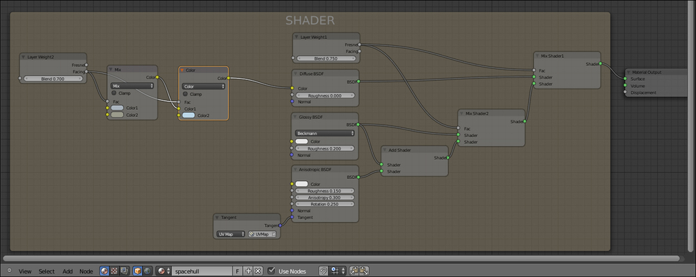
- In the Material window switch the Diffuse BSDF node with a Mix Shader node and rename it Mix Shader1; in the first Shader slot select a Diffuse BSDF node and in the second one a Mix Shader node, rename it Mix Shader2. In the first Shader slot of the Mix Shader2 node select a Glossy BSDF and in the second one an Add Shader node. Connect the Glossy shader also to the first Shader slot of the Add Shader node and in the second one select an Anisotropic BSDF.
- Add a Tangent node (Shift + A | Input | Tangent) and connect it to the Tangent input socket of the Anisotropic shader. In the Method to use for the tangent slot select UV Map and in the slot on the side select the name of the UV coordinates layer assigned to the torus.
- In the Anisotropic shader node set the Roughness to 0.150, the Anisotropy to 0.300, and the Rotation to 0.250.
- Add a Layer Weight node (Shift + A | Input | Layer Weight), rename it Layer Weight1, and connect its Fresnel output to the Fac input sockets of both the Mix Shader1 and Mix Shader2 nodes. Set the Blend factor to 0.750.
- Add a Mix node (Shift + A | Color | Mix): set the Color1 to R 0.400, G 0.458, B 0.500 and the Color2 to R 0.331, G 0.332, B 0.266. Press Shift + D to duplicate it and change the Blend Type to Color: connect the output of the Mix node to the Color1 input socket of the Color node and change the Color2 to R 0.503, G 0.680, B 0.800.
- Add a Layer Weight node (Shift + A | Input | Layer Weight), rename it Layer Weight2 and connect the Facing output to the Fac input sockets of both the Mix and Color nodes. Set the Blend factor to 0.700. Connect the output of the Color node to the Color input socket of the Diffuse BSDF shader.
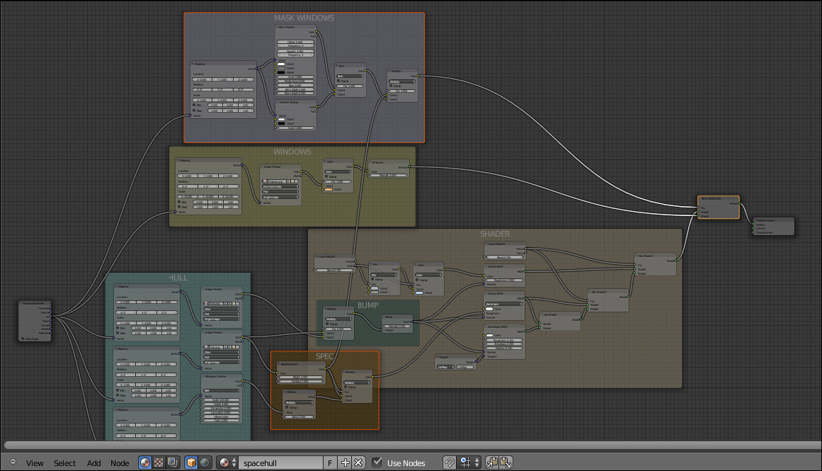
- Add a Frame (Shift + A | Layout | Frame), select all the nodes except for the Material Output one and then the frame and press Ctrl + P to parent them. Rename the frame SHADER.
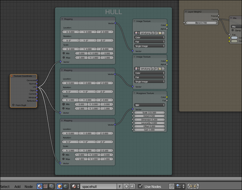
- Add a Texture Coordinate node (Shift + A | Input | Texture Coordinate), a Mapping node (Shift + A | Vector | Mapping), an Image Texture node (Shift + A | Texture | Image Texture), and a Musgrave Texture node (Shift + A | Texture | Musgrave Texture).
- Press Shift + D to duplicate the Image Texture node and place the textures vertically in a column like this from top: Image, Image, and Musgrave.
- Press Shift + D to duplicate the Mapping node two times and place them in a column at the left side of the texture nodes. Connect the UV output of the Texture Coordinate node to the Vector input sockets of the three Mapping nodes. Connect the Vector output of each one of the Mapping nodes to the Vector input socket of each one of the textures.
- Click on the Open button in the first Image Texture nodes to load the image
spacehull.png; click on the little arrows on the left side of the button in the second Image Texture node to select the same image texture. Go to the Musgrave Texture and set the Scale to 115.500, Detail to 4.500, Dimension to 0.200, and Lacunarity to 0.600. - Go to the first Mapping node and set the Scale X 2.000, Y 4.000, and Z 6.000; go to the second Mapping node and set the Scale Y 2.000 and Z 3.000; go to the third Mapping node and set the Scale Z to 0.100.
- Add a Frame (Shift + A | Layout | Frame), select the three Mapping nodes, the two Image Texture nodes, and the Musgrave Texture and then the frame, and press Ctrl + P to parent them. Rename the frame HULL.
- Add a Mix node (Shift + A | Color | Mix), a Bump node (Shift + A | Vector | Bump), and a Frame (Shift + A | Layout | Frame); select the Mix and the Bump nodes and then the frame and press Ctrl + P to parent them. Rename the frame BUMP. Set the Mix node Blend Type to Multiply and connect its output to the Height input socket of the Bump node. Set the Strength to 0.050 and connect the Normal output to the Normal input sockets of the Diffuse, Glossy, and Anisotropic shader nodes.
- Connect the Color output of the first Image Texture node to the Color2 input socket of the multiply Mix node; connect the Color output of the second Image Texture node to the Color1 input socket.
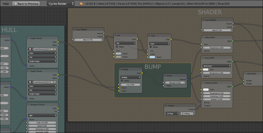
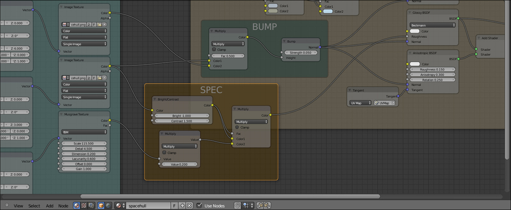
- Now add a Math node (Shift + A | Convertor | Math) and set the operation to Multiply; connect the color output of the Musgrave Texture inside the HULL frame to the first Value input socket and set the second Value to 0.200.
- Add a Bright/Contrast node (Shift + A | Color | Bright/Contrast) and connect the Color output of the second Image Texture node to its color input socket; set the Bright to -1.000 and the Contrast value to 1.500. Add a Mix node (Shift + A | Color | Mix) and set the Blend Type to Multiply; connect the Bright/Contrast node output to the Color1 input socket and the multiply Math node output to the Color2 input socket. Connect also the Bright/Contrast node output to the Fac input socket of the multiply Mix node.
- Connect the multiply Mix node output to the Roughness input socket of the Glossy BSDF shader.
- Add a Frame (Shift + A | Layout | Frame), select the Bright/Contrast node, the multiply Math node, and the multiply Mix node and then the frame and, press Ctrl + P to parent them. Rename the frame SPEC.
- Add a new Mapping node (Shift + A | Vector | Mapping), an Image Texture node (Shift + A | Texture | Image Texture), a Mix node (Shift + A | Color | Mix), and an Emission shader node (Shift + A | Shader | Emission).
- Add a Frame (Shift + A | Layout | Frame), select the former nodes and then the frame, and press Ctrl + P to parent them; rename the frame WINDOWS.
- Connect the UV output of the Texture Coordinate node to the Vector input socket of the new Mapping node, then connect the Mapping node output to the Image Texture Vector input socket; rename the Image Texture node WINDOWS, and connect its Color output to the Color1 input socket of the Mix node, then connect the output of this latter to the Color input socket of the Emission shader.
- In the Mapping node set the Scale to 10.000 for all three axes; in the WINDOWS Image Texture node load the image
spacehull_windows.pngand set the Color Space to Non Color Data. Set the Mix node Blend Type to Color, the Fac value to 1.000, and the Color2 to R 0.800, G 0.478, B 0.177; finally set the Emission node Strength to 2.000. - Now add a Mix Shader node (Shift + A | Shader | Mix Shader) and paste it just right before the Material Output node; rename it ADD WINDOWS. Connect the output of the Emission shader node to the second Shader input socket.

- Add a new Mapping node (Shift + A | Vector | Mapping), a Brick Texture node (Shift + A | Texture | Brick Texture), a Checker Texture node (Shift + A | Texture | Checker Texture), and a Mix node (Shift + A | Color | Mix).
- Add a Frame (Shift + A | Layout | Frame), select the former nodes and then the frame and press Ctrl + P to parent them; rename the frame MASK WINDOWS.
- Connect the UV output of the Texture Coordinate node to the Vector input socket of this Mapping node, then connect the Mapping node output to the Vector input sockets of both the Brick Texture and Checker Texture nodes; connect the Color outputs of both the texture to the Color1 and to the Color2 input sockets of the Mix node.
- Set the Mapping node Scale to 0.500 for all the three axes, then go to the Brick Texture node and set: the Offset and Squash frequency to 3, the Color1 to pure white, the Color2 to RGB 0.500, and the Scale to 5.800. Go to the Checker Texture node and set the Color2 to total black and the Scale to 5.900.
- Set the Mix node Blend Type to Burn and the Fac value to 1.000; connect its output to the Fac input socket of the ADD WINDOWS node. Press Shift + D to duplicate the Burn node and set the Blend Type to Multiply, then paste it right after the Burn node; connect the output of the Bright/Contrast node inside the SPEC frame to the Color1 input socket of the just added Multiply node (this way the connection of the Burn node is automatically moved to the Color2 input socket).
- Add a Mapping node (Shift + A | Vector | Mapping) and an Image Texture node (Shift + A | Texture | Image Texture); rename this latter NAME and load the image
spacehull_name.png(a simple logo made in Gimp with the alpha channel, that is a transparent background). - Connect the UV output of the Texture Coordinate node to the Vector input socket of this Mapping node, then connect the Mapping node output to the Vector input sockets of the Image Texture node.
- Now go to the SHADER frame and add a Mix node (Shift + A | Color | Mix), paste it between the color Mix node and the Diffuse shader; connect the Color output of the NAME Image Texture node to the Color2 input socket of the last added Mix node and the Alpha output to the Fac input socket.
- In the Mapping node click to activate both the Min and Max clipping values, set the Scale X 0.700 and Y 1.600 and play with the Location X and Y values until you see the ARGUS logo appearing on the hull in the location you want (this is dependent on the location of the initial face you choose as the active one for the unwrapping, because every other face has been unwrapped following the location of that active face; in my example I had to set the Location X to -1.900 and Y to 0.100).
- Add a Frame (Shift + A | Layout | Frame), select the Mapping and the Image Texture nodes and then the frame and press Ctrl + P to parent them; rename the frame NAME.

- Go again to the SHADER frame and add a Mix node (Shift + A | Color | Mix), paste it between the Color node and the Mix node; set the Blend Type to Multiply and connect the Bright/Contrast node output to the Color2 input socket, then connect the Layer Weight2 facing output to its Fac input socket.
- Go to the SPEC frame and add a Mix node (Shift + A | Color | Mix), set the Blend Type to Subtract and the Fac value to 0.800, then paste it right after the Multiply node; connect the Color output of the NAME Image Texture to the Color2 input socket.

From step 1 to step 8 we built the general shader for the metallic hull.
From step 9 to step 14 we built the HULL frame group, not immediately used by the shader but that will supply the basic pattern to be used for the bump and for the specular component (and for the color as well). At steps 15 and 16 we added the per-shader bump, by superimposing two differently scaled versions of the same hull panels image coming from the HULL frame group.
From step 17 to step 20 we built the SPEC frame group, by contrasting the HULL component then connected straight to the Glossy shader Roughness; the effect is added to the Anisotropic specularity by the Add Shader node, to give a metallic look. From step 21 to step 25 we built the frame group for the light windows to be added on the hull.
From step 26 to step 30 we made the masking for the windows, to give them a random and not uniform appearance. From step 31 to step 35 we added the name logo to the hull, by using the alpha channel of the image itself as mixing factor.
At step 36 we added a little improvement in the colors by multiplying the contrasted hull panels image and lastly at step 37 we subtracted the logo specularity from the hull, to make it less shiny.
This is where we are so far:

Actually, the appearance of the hull can be even more improved by using some displacement to add details to the spaceship shape, at the moment a little bit too smooth.
- Go to the Object Modifiers window and assign to the Torus a second Subdivision Surface modifier; set the Subdivisions levels to 2 both for View and Render.
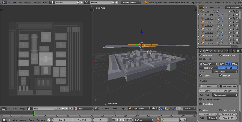
- Assign a Displace modifier, then click on the Show texture in texture tab button on the right side of the Texture slot; in the Textures window click on the New button, then change the default Clouds texture with an Image or Movie texture.
- Click on the Open button and load the texture
spacehull_displ.exr. Go back to the Object Modifiers window and set the displacement Strength to 0.200; in the Texture Coordinates slot select UV.
This way the displacement features get mixed with the hull panels of the shader, giving a nice result. The spacehull_displ.exr is a 32 bits float displacement map baked in the Blender Internal engine (at the moment Cycles doesn't have the possibility to bake textures or shaders). I modeled with planes and scaled cubes a simple greeble panel, then I baked the displacement on a different and unwrapped plane:
If you want to have a look at the scene, open the file 1301OS_06_greeble.blend.
One last thing we can do to improve the model is to assign to the Torus mesh, after the Displace modifier, a Decimate modifier set to Planar with a ratio of 0.3000 or similar; you will inevitably lose some detail but will obtain a lot lighter mesh.
There is an interesting and long thread about the displacement technique on the Blender Artist forum, at the following link: http://blenderartists.org/forum/showthread.php?273033-Sculpting-with-UVs-and-displacements