THE STUDIO ENVIRONMENT
As you’ll learn as you read through this book, audio production can be accomplished in a variety of situations and in a number of different environments. Recording “in the field” may simply entail using a single microphone and portable MP3 recorder or perhaps a setup consisting of a laptop, audio software, and a microphone. On the other hand, recording in the studio may entail multiple microphones and other sound sources feeding into a large audio console or just a basic editing suite. This chapter takes a look at the more formal setting of the traditional audio studio.
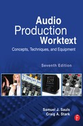
The room that houses the equipment necessary for audio production work and in which the finished product is assembled is known as the production studio. What may initially appear to be merely a roomful of electronic equipment will become a comfortable environment once you’ve become familiar with the space and components that make up the production facility. If your facility has several studios, they may be labeled “Production 1” or “Prod. B” or identified with another abbreviation for the production studio, “PDX.” Today, a streamlined digital “studio” may merely be a workstation desk set up in the corner of a room with a mix of computer and audio equipment, as shown in Figure 2.1.
Most radio stations utilize at least two studios. One is usually delegated as the on-air studio and is used for live, day-to-day broadcasting. The others are audio production studios, used for putting together programming material that is recorded for playback at a later time. This includes such items as commercials (often referred to as “spots”), features, public service announcements (PSAs), and station promotional or image pieces (promos). Regardless of the actual physical size or shape, the production facility is the creative center for a radio station or audio production house. Often the production studio mirrors the on-air studio with the same or very similar equipment configuration and serves as a backup for the on-air room. Some facilities also have a studio that is considered a performance studio or announce booth. It usually is smaller than the other studios and houses nothing more than microphones, headphones, copy stands, a table, and chairs. The output is normally sent to a production studio to be recorded, although sometimes it’s sent directly to the on-air studio for live broadcast. A performance studio can be used for voice-over work, for taping interviews, for discussions involving several guests, or for recording a small musical group or production sound effects.
Two of the biggest concerns for studio design looked at in this chapter are acoustics and ergonomics. Acoustics refers to how sound “behaves” within an enclosed space, and ergonomics refers to design considerations that help reduce operator fatigue and discomfort. Acoustical considerations have become increasingly important because of the high-quality recordings that can be obtained within a digital environment. Although you may never build or remodel an audio studio, an understanding of the characteristics of the production room can help you assess your facility and suggest ways in which you can improve the surroundings that you’ll be working in.

FIGURE 2.1 An audio production environment can be a small editing suite that combines computer and audio equipment. (Image courtesy of Motor Racing Network Radio.)
Figure 2.2 shows a simplified “map” of a typical audio production studio and how a series of audio equipment is interconnected. Starting with various sound sources, such as a microphone or an audio recorder, it shows the route or signal path that sound takes to ultimately be broadcast or recorded. This path is often called an audio chain, because the various pieces of equipment are literally linked together. The trip can be complicated, because the sound can go through several changes along the way. For example, it can be dubbed, or copied, from CD to a recorder; or it can be equalized, which is a form of signal processing. The solid lines show sound being sent to the audio console from an audio source. Then it goes through signal processing equipment and finally to the transmitting system, which would be normal for an on-air studio. The broken line shows the sound being sent back to an audio recorder after signal processing, which would be common for an audio production studio. In both cases, the sound can be heard in the studio through monitor speakers or headphones. You’ll learn more about all of this as you work your way through this text, but for now the diagram in Figure 2.2 provides a look at where you are headed.
The equipment shown is also representative of what could be found in the typical audio production studio. A microphone transforms the talent’s voice into an audio signal. It is not uncommon for a production facility to have one or more auxiliary microphones for production work that requires several voices. Most production rooms also have two CD players, enabling different CDs to be played back-to-back or simultaneously. Besides CD players, many production studios utilize various digital record and playback gear, such as the MiniDisc (MD) recorder, computers with audio software programs, compact disc recorder (CD-R), or digital audio workstations (DAWs). How many recorders or players are found in the production room depends on the complexity of the studio and the budget of the facility. All of this equipment feeds into the audio console, which allows the operator to manipulate the sound sources in various ways. Signal processing equipment, such as an equalizer, noise-reduction system, or reverb unit, is usually put into the audio chain between the audio console and the transmitting or recording equipment; however, most signal processing is now done in postproduction using specialized audio software. Monitoring the sound during production work is accomplished with studio speakers or headphones. Compare Figure 2.2 with Figures 2.5 and 2.10 to see how the audio chain translates into the actual production studio.

FIGURE 2.2 The audio chain shows how equipment is interconnected and how sound moves through that equipment in an audio studio.
Many audio production studios use a U-shaped layout (see Figure 2.3) or some variation of it, because this allows the operator to reach all the equipment control surfaces, and puts the operator immediately in front of the audio console. With the use of remote start/stop switches for any equipment that’s out of the operator’s reach, all equipment manipulation can occur at the audio console once everything has been set up and cued. Today most radio work is done combo; that is, the announcer is also the equipment operator (see Figure 2.4). Because of this setup, the equipment and operator are in a single studio, be it a production or on-air room. This type of studio layout facilitates the working combo. (If you watch re-runs of the television sitcom WKRP in Cincinnati, this method is also employed.) In earlier radio days, the announcer was often located in a separate room or announce booth adjacent to the studio that housed the actual broadcast equipment. Visual contact and communication were maintained via a window between the two rooms. An engineer was required to manipulate the equipment, and the announcer merely provided the voice. Many larger-market radio stations still use a similar announcer/engineer arrangement, popularly known as “engineer-assist” broadcasting.
One of the basic ergonomic considerations in putting the studio together is whether it should be a sit-down or stand-up design. Sit-down studios would have countertops at desk height and would include a chair or stool for the announcer. As the name implies, stand-up operations have counter height set for the announcer to be standing while doing production work. If you’re designing a stand-up studio, make sure that even the shortest person can reach the equipment, especially equipment in turrets or countertop modules. Stand-up allows more movement and tends to provide more energy in delivery. One approach isn’t really better than the other, so it is a personal choice of the individual facility.
2.4 PRODUCTION STUDIO FURNITURE
Studio furniture provides the foundation for the production studio, because all the equipment in the room sets on it, mounts in it, or is wired through it. Studio equipment is often installed on and in custom-built cabinets and counters. Although the cost can be high, such furniture can be built to the exact dimensions of the studio and for the exact equipment that will be housed in that studio. A less expensive but equally functional approach is to lay out the studio using modular stock components (review Figure 2.3). Audio studio furniture has been designed expressly for recorders, audio consoles, and other pieces of studio equipment. Using modular furniture and racks often makes it easier to reconfigure the studio or add additional equipment if the studio needs to expand.
Today’s studio furniture systems also include space and cabinet modules for computer monitors and other computer equipment that’s being integrated with traditional equipment in the audio studio, as shown in Figures 2.5 and 2.10. A computer monitor should be about 2 feet away from the announcer and the topmost screen line should fall slightly below eye level. Monitors that are placed too high, such as on top of a studio module, can cause neck strain. Some monitors can be kept off the studio furniture by using a special wall-mounted or ceiling-mounted TV boom. Flat-screen monitors offer more mounting options, take up less space, are aesthetically pleasing in the audio studio, and have become the standard in most audio studios. If possible, the computer keyboard should be placed in line with the monitor rather than off to the side. Sometimes the keyboard can be placed on an under-counter drawer to accomplish this, but you have to watch the operator’s knee space in such a setup. If possible, avoid putting a keyboard near hard counter edges that can cause a painful problem if the operator’s wrist strikes the counter edge, and make sure that the computer mouse can be reached without stretching the operator’s arm.

FIGURE 2.3 Many audio studios use modular furniture components arranged in a U-shaped design that allows the operator to see and reach all the equipment easily. (Image courtesy of Graham Studios.)

FIGURE 2.4 On-air combo operation. (Photo courtesy of Sauls, S. J. (2007). Basic Audio Production: Sound Applications for Radio, Television and Film, 2nd ed., Thomson Custom Solutions, publisher.)
Most studio furniture is manufactured of plywood or particleboard with a laminate surface; however, a few modern counters are employing a solid-surface countertop of Corian or similar kitchen-counter type material, as shown in Figure 2.5. Both custom-built and modular cabinets and counters are also designed to provide easy access to the myriad cables necessary to wire all the studio equipment together yet maintain an attractive image for the look of the studio. Digital equipment offers the advantage of better cable management, as linking equipment via digital inputs/outputs requires less cable than analog wiring. Other cabinets or storage modules are also available for CDs and other material that may be kept in the production studio. Furniture housing equipment may require cooling, but most digital equipment will operate fine with a passive air flow provided by back panel vents in the furniture. If a forced-air fan is required, be aware of the noise problem it could present.
Does stylish furniture make a studio sound better? Although that notion would be hard to quantify, a positive studio image does imply a commitment to high-quality professional production, and this often translates into more creativity, more productivity, and a better “sound” produced from that studio.
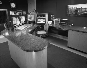
FIGURE 2.5 A solid-surface countertop on studio furniture provides the audio studio with a sleek, modern look. (Image courtesy of Mager Systems, Inc.)
2.5 STUDIO SOUND CONSIDERATIONS
The audio production studio is a unique space, in that the physical room will have an impact on the sound produced in it. Because of this, several characteristics of sound should be considered in designing the studio, including sound isolation, noise and vibration control, and room acoustics. When sound strikes a surface (such as a studio wall), some of that sound is reflected, while some is absorbed within or transmitted through the material of the surface. Most of the sound that hits a hard, flat surface will be reflected. However, if the surface is irregular, it will break up the sound wave and disperse the reflections—a phenomenon known as diffusion. Sound that’s absorbed into the surface is dissipated within it, but penetration occurs when sound goes through a surface and is transmitted into the space on the other side. Figure 2.6 illustrates that penetration, absorption, reflection, and diffusion are all characteristics that help determine the sound that is both produced and reproduced in the studio.
When a sound (such as a talent’s voice) is produced, the direct sound is the main sound that you hear. In a production situation, it is sound that goes from the sound source straight to the microphone. On the other hand, indirect or reflected sound reaches the microphone fractions of a second after the direct sound does because it has traveled a circuitous route. Reflected sound consists of echo and reverberation (reverb). This indirect sound has bounced off or been reflected from one surface (echo) or two or more surfaces (reverb) before reaching the microphone (see Figure 2.7). Because it’s an early reflection, echo provides a distinct repetition of the sound, such as “hello—hello—hello.” On the other hand, a reverb’s repeated later reflections provide a continuous decay of the sound, such as “hello—oo—oo.” The components of direct and indirect sound make up what is commonly called the sound’s life cycle.

FIGURE 2.6 Sound striking an audio studio wall will reflect off, penetrate through, be diffused by, or be absorbed by that surface.

FIGURE 2.7 Direct sound takes a straight path from the talent to the microphone, but reflected sound is also produced in the audio studio.
In designing the audio studio, the goal is to manipulate these sound characteristics to create a proper sound environment for production work. When considering reflected sound, we think in terms of reverb ring and reverb route, with the same concepts applying for echo but to a lesser extent. Reverb ring (or reverb time) is the time that it takes for a sound to die out or go from full volume to silence. Reverb route is the path that sound takes from its source to a reflective surface and back to the original source (or a microphone, if recording). Excessive reflected sound tends to accent high and midrange frequencies, which produces a “harsh” sound; to blur the stereo image, which produces a “muddy” sound; or to cause standing waves (see Section 2.7), which produces an “uneven” sound. Reflected sound can also be reinforced sound, which causes objects or surfaces within the studio to vibrate at the same frequencies as the original sound in a sympathetic fashion.
Both absorption and diffusion are used to control reflected sound. Part of the reflected sound can be absorbed within the carpeting, curtains, and walls of the studio. Absorption soaks up sound and shortens reverb time to prevent excessive reflection. Absorption provides a dead studio, which has a very short reverb ring (sound dies out quickly) and a long reverb route that produces a softer sound. Excessive absorption produces a totally dead studio, which provides a “dry” sound that is unlike any normal acoustic space and isn’t really desirable. In contrast, a live studio has a longer reverb ring and a shorter reverb route that produces a harder or more “brilliant” sound. Diffusion uses irregular room surfaces to break up sound reflections. This decreases the intensity of the reflections, making them less noticeable, but doesn’t deaden the sound as much, because the sound reflections are redirected rather than soaked up. Most studio designs control reflections by a combination of absorption and diffusion techniques.
One common audio studio design is a live end/dead end (LEDE) approach. The front of the studio (where the operator and equipment are located) is designed to absorb and diffuse sounds. This dead end quiets some of the equipment operation noise, picks up the direct sound of the talent’s voice, and absorbs the excess reflections that pass by the microphone from the live end. The live end, or back, of the studio adds a desirable sharpness to the sound by providing some reflected sound so the studio isn’t totally dry. Other acoustic designs include early sound scattering (ESS), which uses a great deal of diffusion, and reflection-free zone (RFZ), which uses a great deal of absorption to control unwanted reflected sound in the studio.
2.6 STUDIO CONSTRUCTION MATERIALS
Another design consideration involves the actual construction materials used for the studio. Ideally, you want to keep penetration to a minimum by keeping outside (unwanted) sound from entering the studio and inside sound from escaping from the studio, except via the audio console. Audio studios utilize soundproofing to accomplish this sound isolation. Doors are heavy-duty and tightly sealed; windows are often double-glassed with the interior pane slanted downward to minimize reflected sounds; and walls, ceiling, and flooring are covered with special sound-treatment materials. For example, studio walls may be covered with acoustically treated and designed panels that both absorb and trap reflected sounds (see Figure 2.8). Some stations use carpeting on the studio walls, but this type of soundproofing doesn’t absorb low frequencies very well. In the past, some production studios used egg cartons on the walls as a sound treatment. If you compare the design of an egg carton with the design of the acoustic panel shown in Figure 2.8, you’ll see why the inexpensive egg carton route worked—to a degree.

FIGURE 2.8 Acoustic panels and tiles help control reflected sound through both absorption (by the foam material) and diffusion (by the irregular surfaces). (Image courtesy of Auralex Acoustics, Inc. Photo by Erikk D. Lee.)
All materials absorb sound to some degree, but each material will have a different absorption coefficient, which is the proportion of sound that it can absorb. A coefficient value of 1.00 indicates that all sound is absorbed in the material. On the other hand, a coefficient value of 0.00 means that no absorption occurs and that all the sound is reflected back. Hard, smooth surfaces like plaster or panel walls and hardwood floors have low absorption coefficients. Heavy, plush carpets, drape-covered windows, and specially designed acoustic tiles have higher coefficients. For example, using a 1,000 Hz tone as the sound source, the absorption coefficient of a sheet rock wall is 0.04, and that of a 2-inch Sonex foam tile is 0.81; the absorption coefficient of a glass window is 0.12, and that of a window curtain is 0.75; the absorption coefficient of a painted concrete block wall is 0.07, and that of a carpeted concrete wall is 0.37. The purpose of any soundproofing material is to help give the studio a dead sound. Soundproofing absorbs and controls excess reverb and echo and helps produce a softer sound.
In order to prevent unwanted sounds from entering a recording studio, quite often a type of sound lock is incorporated in the studio design. A sound lock is a small area located outside both the control room and performance area that captures sound and will not allow it to pass through. A simplistic design of a sound lock is presented in Figure 2.9. (See Sauls, S. J. (2007). Basic Audio Production: Sound Applications for Radio, Television, and Film, 2nd ed., Thomson Custom Solutions, publisher, p. 1–13.)

FIGURE 2.9 Studio sound lock. (Figure courtesy of Sauls, S. J. (2007). Basic Audio Production: Sound Applications for Radio, Television, and Film, 2nd ed., Thomson Custom Solutions, publisher.)
The size and shape of a production studio can also determine how reflective the studio is. As noted, the audio production studio shouldn’t be overly reflective, because sound produced or recorded would be too bright and even harsh. Unfortunately, standard room construction often counters good studio design. For example, studios with parallel walls (the normal box-shaped room) produce more reflected sound than irregularly shaped studios. Sound waves that are reflected back and forth within a limited area, such as between studio walls that are parallel, can produce standing waves. In basic terms, a standing wave is a combination of a sound wave going in one direction and its reflected wave going in the opposite direction. If the distance between the walls is the same as the wave length (or a multiple of it), the waves interact and produce an undesirable combined sound that tends to be uneven, as previously mentioned. To help prevent standing waves, adjacent studio walls can be splayed (joined at an angle of more than 90 degrees) to help break up reflected sound and control excessive reverb and echo. The wall must lean so that the wave will bounce off and be absorbed into the carpet. Concave walls tend to collect sound, while convex walls tend to push away sound. Many people are surprised how “dead” it sounds in a recording studio (due to the lack of standing waves). Areas with many standing waves are known as “live” rooms, which are undesirable.
The actual size of the production facility is partially determined by the equipment that must be housed in it. However, in constructing the audio production room, consideration should be given to the fact that when rooms are built with height, width, and length dimensions that are equal or exact multiples of each other, certain sound frequencies tend to be boosted, and other sound frequencies tend to be canceled. As this “peaks and valleys” sound is not desirable in the audio production room, cubic construction should be avoided when possible.

FIGURE 2.10 Any audio studio should be a comfortable and functional environment. (Image courtesy of Arrakis Systems, Inc. www.Arrakis-Systems.com.)
There are some studio design considerations that can be categorized as the “aesthetics” of the production room. In general, any studio should be pleasant to work in; after all, the operator may be confined to a rather small room for long stretches of time. For example, fluorescent lighting should be avoided when possible. Not only does it tend to introduce “hum” into the audio chain, but it’s also harsher and more glaring than incandescent light. If possible, the studio lights should be on dimmers so that an appropriate level of light can be set for each individual operator. If the lighting causes glare on a computer monitor, use an antiglare shield or screen to diminish this problem or use track lighting that can be directed away from the screen.
Stools or chairs used in the audio studio should be comfortable and functional. Userfriendly adjustments should allow the user to set the seat height so that the entire sole of the foot rests on either the floor or a footrest. Chairs must move easily, because even though most of the equipment is situated close to the operator, they may have to move around to cue CDs or speak directly into the microphone. The production stool must also be well constructed so that it doesn’t squeak if the operator moves slightly while the microphone is open. This may not be a factor for production studios designed for a stand-up operation in which there is no stool, and with counters at a height appropriate for the operator to be standing while announcing. As mentioned earlier, the stand-up operation allows the operator to be more animated in his or her vocal delivery and actually provides a better posture for speaking than a sitting position.
Many radio production rooms are decorated with music posters or radio station bumper stickers and paraphernalia. Not only does this feature keep the studio from being a cold, stark room, but it also gives the studio a radio atmosphere. Figure 2.10 shows the interior of a typical radio production studio. An audio production facility may decorate with paintings or art posters to give the facility a more business-like, professional feel.
PRODUCTION TIP 2A
Static Electricity
Static electricity can be a problem in production studios, because of the heavy use of carpeting. Most people don’t enjoy getting shocked every time they touch the metal control surface of an audio console. Also, some modern audio equipment and computer systems have electronic circuits that can be disrupted by static discharges. There have been instances where audio recorders have switched into “play” mode when an operator just “sparked” the faceplate of the machine. If design factors can’t keep the studio free from static, commercial sprays can be put on the carpeting or spray fabric softener can be used to provide an antistatic treatment at a modest cost. Dilute the fabric softener a bit or you’ll build up a dangerous, slippery gloss on your carpets. A static touch pad can also be used in the studio—the operator merely places a finger on the pad to harmlessly discharge static buildup. Some studios have even been built with conductive laminate countertops connected to the studio’s ground system to help minimize static.
On-air lights (see Figure 2.11) are usually located outside the audio production room or studio. Normally they are wired so that whenever the microphone in that studio is turned on, the on-air light comes on. A light outside an audio production studio will often read “recording” instead of “on air.” In either case, a lit light indicates a live microphone.

FIGURE 2.11 When lit, the on-air or recording light indicates that a microphone is “live” in that audio studio.
Good production practice dictates that when an on-air light is on, you never enter that studio, and if you’re in the vicinity of the studio, you are quiet. Inside the studio, another alert light may come on when the microphone is turned on and the announcer often says “Standby” to alert others in the studio that he or she is preparing to turn on the microphone.
Hand signals don’t play a major role in modern audio production; however, there are situations when vocal communication isn’t possible and hand signals are necessary. For example, if a voice-over talent and engineer are recording from adjacent studios with a window between them, as mentioned earlier in this chapter, they must be able to communicate with each other. There are also times when two announcers must communicate in a studio, but an open or live microphone prevents them from doing so verbally. Because of situations like these, hand signals have evolved over the years to communicate some basic production information. Figure 2.12 shows some of the basic hand signals.
Often hand signals concern getting a program started or stopped. A standby signal is given just prior to going on air and is immediately followed by the cue talent signal. To convey “You’re on,” this cue is given by pointing your index finger (using the same hand that gave the standby signal) at the person who’s supposed to go on air. The common signal for stopping a program is the hand across the throat gesture or cut signal. This signal terminates whatever is happening at the moment and usually “kills” all live microphones and stops all recorders. Some hand signals are used to give directions to the talent regarding the microphone. To get the talent to give mic level, for example, hold one hand in front of you and open and close the thumb and fingers in a “chattering” motion to indicate that he or she should talk into the microphone so that levels can be checked.
Other hand signals are often used during a production to let the talent know how things are going or to convey some necessary information. Timing cues are given with the fingers with each finger indicating 1 minute. Using both index fingers to form a cross in front of you means there are 30 seconds left. Timing cues always indicate how much time remains in the program because there is nothing you can do about the time that has already gone by. When everything is going fine, the radio hand signal is the traditional “thumbs-up” given with clenched fist and extended thumb or the “OK” of the circle and three fingers. There is no universal set of hand signals, so you may find that your facility uses some that are different, uses some not presented here, or doesn’t use any at all. In any case, an understanding of hand signals should prove helpful in certain production situations.

FIGURE 2.12 Hand signals allow information to be conveyed in the audio studio when a “live” microphone prevents verbal communication.
Noise is inherent in any of the electronic equipment housed in audio production studios. The term noise refers to any unwanted sound element introduced in the production process that was not present in the original sound signal. For example, a microphone that employs an extremely long cable might add noise to the audio signal. Recorders can introduce noise from mechanical gears or just through the electronic circuits used in amplifying or recording the signal. In all audio production, the noise level should be kept as low as possible. Most audio equipment is designed to produce a signal-to-noise ratio (S/N) of at least 60 to 1. S/N is an audio measurement, usually in decibels, that specifies the amount by which a signal at a standard test level exceeds the level of noise produced by an electronic component. The higher the signal-to-noise level, the better. For most analog equipment, an S/N of around 60 dB is considered good quality; modern digital equipment can show an S/N ratio of 98 dB. The S/N gives an indication of the equipment’s ability to reproduce sound cleanly.
Distortion is an unwanted change in the audio signal due to inaccurate reproduction of the sound. One example is loudness distortion, which can occur when a signal is recorded at a level that is too loud for the equipment to handle. An overdriven or too loud signal sounds “muddy,” and the reproduced signal does not have the same clarity or sharpness as the original. You should be aware of noise and distortion when working with audio equipment, especially analog equipment. Digital equipment frequently reduces the chance of introducing noise into your production work, but sometimes your work will be accomplished using a combination of analog and digital equipment.
Analog signals of 100 percent would equate to digital signals at –12 dB. This provides “headroom” from –12 dB to 0 in the digital domain. (Actually, there is no agreed upon standard for the relationship between 0 VU and its equivalent in the digital world. Panasonic, for instance, states –18 dB for their professional machines, while Sony suggests –12 dB.) If the signal goes over 0 in digital, it will “clip” and will be distorted. Because of its “discrete” processing, there is basically no signal toleration above 100 percent saturation in the digital realm. As there is no headroom in digital recording, audio producers must allow some into their recordings. On the other hand, analog recording is more forgiving and allows for total saturation with little distortion if the signal peaks at just above 100 percent, as discussed in Chapter 5. This, along with the natural sound, is one of the main reasons some audio engineers still prefer to master (originate) in analog recording.
FIGURE 2.13 The production of sound requires vibrations, which are transmitted through a medium to a receiver.
2.12 IS IT A SOUND SIGNAL OR AN AUDIO SIGNAL?
We’ve already mentioned how sound acts in the audio studio. It is worth your while to continue to consider sound, as this will help you understand many aspects of the production process discussed in the rest of the text. Much of what happens in the production studio has to do with manipulating sound, whether it involves a sound signal or an audio signal. When sound is naturally produced (for example, when talent speaks into a microphone), we think of that sound (his or her voice) as a sound signal.
In audio production, when that sound signal is then manipulated electronically (such as recorded into a digital recorder), it is called an audio signal. Obviously, most audio production must start at some point with a sound signal, but during the actual production process, we are often recording and manipulating an audio signal. To further complicate things, these terms are sometimes interchanged when people talk about various production processes.
When something vibrates, sound is generated. For example, plucking a single guitar string causes a mechanical vibration to occur, which we can easily see by looking at the string. Of course, we can also hear it. The vibrating string forces air molecules near it to come together, slightly raising the air pressure and pushing those molecules into motion, which in turn sets neighboring air molecules in motion, and on and on. Thus sound develops waves (like a stone dropped into water), which vibrate up and down and set the air molecules in a push (compression) and pull (rarefaction) motion, causing an area of higher pressure to move through the air. So in addition to the vibration noted previously, we need a medium for the sound to travel through. Of course, the medium we’re usually concerned with is the atmosphere, or air. Sound can also travel through other materials, such as water or wood, but will often be distorted by the medium. Sound vibrations can’t travel in a vacuum. Finally, for sound to exist technically, we need a receiver. Someone (a person) or something (a microphone) must receive it and perceive it as sound. The high-pressure area reaches receptors in our ear and we hear the vibrations as sound, or the pressure waves strike the diaphragm of a microphone, beginning the process of converting a sound signal into an audio signal.
Figure 2.13 shows a representation of sound being produced. We can’t actually see sound waves, but they act very much like water waves as we’ve noted. The sine wave (shown in Figure 2.14C) is used to represent a sound waveform, because it can readily show the wave compression (the higher pressure portion of the wave above the center line) and the wave rarefaction (the lower pressure portion of the wave below the center line).
2.14 KEY CHARACTERISTICS OF SOUND WAVES
There are four key characteristics of sound that help determine why one sound is different from another: amplitude, frequency, timbre, and the sound envelope. A sound wave’s amplitude relates to its strength or intensity, which we hear as volume, or loudness. The loudness of a sound can be thought of as the height of the sound wave. The louder the sound is, the higher the amplitude as shown in Figure 2.14A. As a sound gets louder, greater compression and rarefaction of air molecules take place, and the crest of the wave will be higher while the trough of the wave will be deeper. A sound wave’s actual amplitude is readily measured; however, loudness is a subjective concept. What is loud to one person isn’t necessarily loud to another person. Sound amplitude is measured in decibels (abbreviated dB). The human ear is very sensitive and can hear a tremendous range of sound amplitudes, so the decibel scale is logarithmic. Near total silence is noted as 0 dB, a sound 10 times louder than this is 10 dB, a sound 100 times more powerful is 20 dB, and so on. Decibels represent the ratio of different audio levels and measure the relative intensity of sound. Sounds in the range of 0 Db (the threshold of hearing) to 120 dB (the threshold of pain) are detected by the human ear, but those sounds near and exceeding the high end can be painful and can damage your hearing. Any sound above 85 dB can cause hearing loss, but it depends on how close the listener is to the sound and how long he or she is exposed to it. The sound at many rock concerts has been measured around the 120 dB range, which explains why your ears often ring for a day or two after the show.

FIGURE 2.14 Characteristics of sound waves include volume, pitch, and tone, here visualized as sine waves.
Frequency relates to the number of times per second that a sound wave vibrates (goes in an up-and-down cycle), which we hear as pitch (see Figure 2.14B). The faster something vibrates, or the more cycles it goes through per second, the higher the pitch of the sound. Like amplitude, frequency can be objectively measured, but like volume, pitch is subjective. In audio jargon, cycles per second are known as hertz (Hz). A sound wave that vibrates at 2,000 cycles per second is said to have a frequency of 2,000 Hz. When the number of cycles per second gets higher—for example, 20,000 Hz—the term kilohertz (kHz) is often used. It denotes 1,000 cycles per second, so 20,000 Hz could also be called 20 kHz. (You’ll learn more about frequency in the next section.)
A sound’s wavelength is the distance between two compressions (crests) or two rarefactions (troughs). Sound wavelength can vary from around 3/4 inch for a treble sound near 16 kHz to around 36 feet for a bass sound near 30 Hz. There is an inverse relationship between wavelength and pitch, so higher-pitched sounds have a shorter wavelength.
A sound’s timbre (which is pronounced “TAM-bur”), or tone, relates to the waveform of the sound. It’s the characteristic of sound that distinguishes one voice from another, even though both may be saying the same thing at the same volume and pitch. A graphic representation of a pure tone is shown as the shape of a sine wave, as in Figure 2.14C. Each sound has one basic tone that is its fundamental; most sound, however, is a combination of many tones with different strengths at different frequencies, so the waveform is much more complex, as shown in Figure 2.14D. These other pitches are either exact frequency multiples of the fundamental (known as harmonics) or pitches that are not exact multiples of the fundamental (known as overtones). For example, striking an A note (above middle C) on a piano would produce a fundamental tone of 440 Hz. In other words, the piano string is vibrating 440 times per second. The harmonics of this note will occur at exact (or whole number) multiples of the fundamental tone, such as 880 Hz (twice the fundamental) or 2,200 Hz (five times the fundamental). The interaction of the fundamental, harmonics, and overtones creates the timbre of any particular sound.
When sound waves combine, they will be either in phase or out of phase. If the peaks and troughs of two waves line up, they will be in phase and combine into one wave with twice the amplitude of the original waves. If the peaks of one sound wave line up with the troughs of another, they will be 180 degrees out of phase and will essentially cancel each other out, producing no sound or greatly diminished sound. Most sound (such as voice or music) is made up of a combination of sound waves that are out of phase, but less than 180 degrees off, thus producing the complex waveform mentioned previously.
A sound’s wave envelope relates to its duration, or the change in volume of a sound over a period of time, as shown in Figure 2.15. Normally, a sound’s wave envelope develops through four specific stages: attack, the time it takes an initial sound to build to maximum volume; decay, the time it takes the sound to go from peak volume to a sustained level; sustain, the time the sound holds its sustain volume; and release, the time it takes a sound to diminish from sustain volume to silence. In essence, decay, sustain, and release refer to the time it takes a sound to die out. Some sounds, like a percussive drum beat, have a very fast attack; other sounds, like a piano chord, have a long decay-sustain-release. Audio equipment must be able to accurately reproduce any sound wave envelope.

FIGURE 2.15 The sound wave envelope depicts the change in volume of a sound over a period of time. (Image courtesy of Sauls, S. J. (2007). Basic Audio Production: Sound Applications for Radio, Television, and Film, 2nd ed., Thomson Custom Solutions, publisher.)
The envelope of sound is, in essence, its “fingerprint.” For the most part, no two sound sources have the same envelope. Along with timbre, the sound envelope is another reason why a saxophone, pipe organ, and flute, all playing the same note, sound different. In addition, quite often in postproduction we manipulate the specific parts of the sound envelope to achieve a desired sound, whereby the sound engineer alters the original make-up of the sound that was initially recorded.
In audio production, we often mention the frequency response of equipment or, for that matter, the frequency response range of human hearing. In very general terms, the human ear is able to hear frequencies within the range of 20 to 20,000 cycles per second. For most of us, it’s not quite that low or that high. In any case, production equipment, such as an audio console or monitor speaker, should be able to reproduce an audio signal in that range, and most modern equipment is measured by how well it does so. For example, a monitor speaker may have a frequency response of 40 Hz to 18 kHz, meaning that the speaker can accurately reproduce all frequencies within that range. An inexpensive broadcast microphone may have a frequency response of only 80 Hz to 13 kHz. It would not be able to pick up any of the higher frequencies—those above 13,000 Hz. This may not be a problem if the microphone were used primarily to record speech because the human voice usually falls in a frequency range of 200 to 3,000 Hz. Obviously, if you wanted to record a musical group (which often produces sounds in the full range of frequencies), you would want to use a microphone with a wider frequency response.
A frequency response curve is often used to indicate the level of frequency response because some equipment may not pick up or reproduce certain frequencies as well as others. Broadcast equipment is designed to pick up all frequencies equally well, so its response curve is considered to be flat, although few components have a truly flat frequency response curve.
Although there are no standard figures, the audio frequency spectrum is often divided into three regions: bass, midrange, and treble. The low frequencies (bass) are those between 20 and 250 Hz and provide the power, or bottom, to sound. Too little bass gives a thin sound, and too much bass gives a boomy sound. The midrange frequencies fall between 250 and 4,500 Hz. These frequencies provide a lot of sound’s substance and intelligibility. Too little midrange gives a lack of presence, but too much midrange gives a harsh sound. High frequencies (treble) are those from 4,500 Hz to 20,000 Hz. The treble frequencies provide the sound’s brilliance and sharpness. Too little treble gives a dull sound, and too much treble gives excess sparkle as well as increasing the likelihood of hearing noise or hiss in the sound.
As frequencies change, we think in terms of the musical interval of the octave, or a change in pitch caused by doubling or halving the original frequency. For example, a sound going from bass to midrange to treble frequencies by octave intervals would go from 110 Hz to 220 Hz to 440 Hz to 880 Hz to 1,760 Hz to 3,520 Hz to 7,040 Hz, and so on. As humans, we are subject to an awkwardly named equal loudness principle. That is, sounds that are equally loud will not be perceived as being equally loud if their pitch is different—we hear midrange frequencies better than either high or low frequencies. In audio production (and other forms of sound manipulation), we often compensate for this by equalization of the signal.
Unless you’re building an audio production facility from the ground up, you will probably have little control over the construction of the studio; sound treatment is an important consideration, however, and methods of improving the sound environment can be put into practice in almost any situation. Although the audio studio may seem overwhelming at first, it is an environment you will become very comfortable in as you do production work. Completion of this chapter should have you in the audio production studio and ready to learn the procedures and techniques for operating all the equipment you see in front of you.
1. What does the radio expression “to work combo” mean?
a) The announcer has an engineer to operate the studio equipment.
b) The announcer operates the studio equipment and also announces.
c) The announcer works at two different radio stations.
d) The announcer is announcing in both the on-air and the production studio.
2. Which type of studio is least likely to contain an audio console?
a) on-air studio
b) production studio
c) PDX studio
d) performance studio
3. Which term describes sound produced in the audio studio that causes objects or surfaces within the studio to vibrate sympathetically?
a) absorbed sound
b) reflected sound
c) reinforced sound
d) diffused sound
4. In the production studio, sound that has bounced off one surface before reaching the microphone is called what?
a) echo
b) reverberation
c) direct sound
d) indirect sound
5. What does “reverb ring” in the production studio refer to?
a) the circular route reflected sound takes before it reaches the microphone
b) the time it takes reflected sound to go from full volume to silence
c) just another common name for echo
d) a sound that has bounced off two or more surfaces
6. What is the use of carpeting on the walls of some audio production facilities an example of?
a) an inexpensive way of decorating the studio
b) producing reverb in the studio
c) producing a live sound in the studio
d) soundproofing the studio
7. Studios with parallel walls produce less reflected sound than irregularly shaped studios.
a) true
b) false
8. Why do most production studios use a U-shaped layout?
a) This design places equipment within easy reach of the operator.
b) This design uses incandescent lights rather than fluorescent lights.
c) This design necessitates custom-built cabinets.
d) This design uses the least amount of wire to connect the equipment.
9. Static electricity is not a problem in the modern production studio, because state-of-the-art audio equipment is impervious to static.
a) true
b) false
10. Which hand signal almost always comes immediately after the standby hand signal?
a) 2 minutes to go
b) thumbs up
c) cue talent
d) give mic level
11. If you hold up the index, second, and third fingers of one hand in front of you, what are you telling the announcer?
a) There are 3 minutes left in the program.
b) There are 30 seconds left in the program.
c) He or she should move three steps closer to the microphone.
d) Three minutes have gone by since the beginning of the program.
12. What does one call the linking of a CD player to an audio console, the console to an equalizer, and the equalizer to an audio recorder?
a) audio road map
b) audio linking
c) audio processor
d) audio chain
13. What do we call the uneven sound that is produced when sound waves are reflected between parallel walls in such a manner that a wave reflected in one direction is combined with an identical wave going in the opposite direction?
a) a diffused wave
b) a standing wave
c) an absorbed wave
d) a sympathetic wave
14. When a “recording” light is on outside a production studio, it means a microphone is “live” in that studio.
a) true
b) false
15. If an audio studio has a live end/dead end design, the front of the studio is the “live end.”
a) true
b) false
16. When sound produced in the production studio strikes a hard, flat surface, which of the following does not happen?
a) reflection
b) absorption
c) penetration
d) diffusion
17. A production studio wall that has an absorption coefficient of 0.50 will absorb half the sound striking it and reflect back half the sound.
a) true
b) false
18. Posters and other radio station paraphernalia should not be put up in a production studio as they will distract the announcer from doing good production work.
a) true
b) false
19. Which term describes what happens when the irregular surfaces of acoustic tiles break up sound reflections?
a) absorption
b) reflection
c) penetration
d) diffusion
20. What is an unwanted change in the audio signal due to inaccurate reproduction of the sound called?
a) reverb
b) noise
c) distortion
d) diffusion
21. Which statement about sound is not true?
a) Sound is generated when something vibrates.
b) Sound, to technically exist, must be heard.
c) Sound vibrations develop waves by setting adjacent air molecules in motion.
d) Sound vibrations travel faster in a vacuum than in air.
22. Which of the following is not part of a sound wave’s envelope?
a) attack
b) decay
c) sustain
d) rarefaction
23. The number of times a sound wave vibrates (goes in an up-and-down cycle) per second determines which characteristic of the sound?
a) frequency
b) amplitude
c) wavelength
d) wave envelope
24. What is the standard unit of measure to gauge the relative intensity of sound?
a) signal-to-noise ratio
b) hertz
c) absorption coefficient
d) decibel
25. Sound (such as a talent’s voice) that has been manipulated electronically (such as recorded on a digital recorder) is called a sound signal.
a) true
b) false
If you answered A to any of the questions:
1a. No. This is not working combo. (Reread 2.3.)
2a. No. An on-air studio needs an audio console for sending the mixed signal out. (Reread 2.1 and 2.2.)
3a. No. If anything, absorbed sound would be diminished. (Reread 2.5.)
4a. Yes. Echo is sound that has reflected off a single surface.
5a. No. This answer nearly (but not exactly) describes reverb route. (Reread 2.5.)
6a. No. Painted walls would be less expensive, so this can’t be correct. (Reread 2.6 and 2.8.)
7a. No. Just the opposite is true. (Reread 2.7.)
8a. Right. The operator can reach around the “horseshoe.”
9a. No. Just the opposite is true. (Reread Production Tip 2 A.)
10a. No. The 2-minute signal would not come until the end of a program. It would not be right after a standby signal. (Reread 2.10.)
11a. Yes. This is the correct hand signal.
12a. No. Although you could map out this audio signal route, this is not the best answer. (Reread 2.2.)
13a. No. Diffused waves would be sound reflections that have been broken up. (Reread 2.5 and 2.7.)
14a. Right. On-air and recording lights usually come on automatically when a microphone is on in that studio.
15a. No. This statement is not true because the front of the studio would be the “dead end” designed to absorb and diffuse sounds. (Reread 2.5.)
16a. No. Most of the sound that strikes a hard, flat surface will be reflected. (Reread 2.5.)
17a. Yes. This would be a true statement.
18a. Wrong. Posters and other studio decorations aren’t likely to cause poor production work, and they do add atmosphere to the studio. (Reread 2.8.)
19a. No. Absorption would be the soaking up of sound reflections. (Reread 2.5 and 2.6.)
20a. No. Reverb is a form of reflected sound. (Reread 2.5 and 2.11.)
21a. No. This is a true statement. (Reread 2.13.)
22a. No. Attack is the time it takes an initial sound to build up to full volume. (Reread 2.14.)
23a. Yes. This is the correct answer.
24a. No. Although S/N is expressed in decibels, it measures the nominal output of audio equipment in relation to the equipment’s noise level. (Reread 2.14.)
25a. No. This is not a true statement, because once natural sound has been manipulated electronically, it is correctly called an audio signal; however, be aware that sometimes these terms are interchanged. (Reread 2.12.)
If you answered B to any of the questions:
1b. Correct. The announcer is also the equipment operator when working combo.
2b. No. A production studio needs an audio console for mixing. (Reread 2.1 and 2.2.)
3b. No. Reflected sound is sound that has bounced off a surface. (Reread 2.5.)
4b. No. Reverb is sound that has reflected off two or more surfaces. (Reread 2.5.)
5b. Yes. This is what we call “reverb ring.”
6b. Wrong. Carpeting absorbs sound and reduces reverb. (Reread 2.5 and 2.6.)
7b. Yes. This is the correct response.
8b. No. Lights have no relevance, so this can’t be correct. (Reread 2.3 and 2.8.)
9b. Yes. Modern electronics, especially logic circuits, can be disrupted by static discharges.
10b. Wrong. You wouldn’t know the production was going well if it hadn’t started yet. (Reread 2.10.)
11b. No. Crossed index fingers indicate 30 seconds left. (Reread 2.10.)
12b. No. This is not correct. (Reread 2.2.)
13b. Correct. This is the right answer.
14b. No. This is exactly what it means. (Reread 2.9.)
15b. Yes. This is a false statement. The “live end” would be the back of the studio designed to add some reflected sound giving the studio sound a desirable sharpness.
16b. This isn’t a bad choice, but some sound will be absorbed and dissipated even with hard surfaces. (Reread 2.5.)
17b. No. A coefficient value of 1.00 would mean total absorption and a coefficient value of 0.00 would mean no absorption. (Reread 2.6.)
18b. Yes. This is the correct answer.
19b. No. Reflection would be sound that has bounced off a surface. (Reread 2.5)
20b. No. You’re close because noise is an unwanted element introduced into the audio signal that was not present in the original sound, but there’s a better response. (Reread 2.11.)
21b. No. This is a true statement. (Reread 2.13.)
22b. No. Decay is the time it takes sound to go from peak volume to a sustain level. (Reread 2.14.)
23b. No. Amplitude relates to volume and the height of a sound wave. (Reread 2.14.)
24b. No. Hertz is another term for cycles per second and is a measure of frequency. (Reread 2.14.)
25b. Correct. This is a false statement because once natural sound has been manipulated electronically, it is correctly called an audio signal; however, be aware that sometimes the terms are interchanged.
If you answered C to any of the questions:
1c. No. This is not working combo. (Reread 2.3.)
2c. No. This is just another term for production studio. (Reread 2.1 and 2.2.)
3c. Right. This is the correct response.
4c. No. Direct sound doesn’t bounce off any surface before reaching the microphone. (Reread 2.5.)
5c. No. Echo and reverb are both reflected sound but distinctly different. (Reread 2.5.)
6c. No. Just the opposite would happen. Soundproofing with carpeting would help produce a dead sound in the studio. (Reread 2.5 and 2.6.)
8c. No. In a cost-conscious facility, this could be a negative. (Reread 2.3 and 2.4.)
10c. Correct. “Standby” and “cue talent” hand signals are always given one after the other.
11c. No. There is another hand signal to move the announcer closer to the microphone, and exact steps are never indicated. (Reread 2.10.)
12c. No. You are way off base with this answer. An audio processor is used to alter the sound characteristics of an audio signal. (Reread 2.2.)
13c. No. Absorbed waves would be sound reflections that have been soaked up. (Reread 2.5 and 2.7.)
16c. No. Some sound will penetrate a hard surface and be transmitted to the adjoining space. (Reread 2.5.)
19c. No. Penetration would be sound that has been transmitted through a surface. (Reread 2.5.)
20c. Yes. You’re correct.
21c. No. This is a true statement. (Reread 2.13.)
22c. No. Sustain is the time a sound holds its volume. (Reread 2.14.)
23c. No. Wavelength refers to the distance between two wave compressions or rarefactions. (Reread 2.14.)
24c. No. Absorption coefficient measures the degree to which materials can absorb sound. (Reread 2.14.)
If you answered D to any of the questions:
1d. No. This seems improbable and is not working combo. (Reread 2.3.)
2d. Correct. A performance studio usually only has microphones that are fed to an audio console in either a production studio or an on-air studio.
4d. You’re partly right, but echo and reverb are both indirect sound, and one is a better response to this question. (Reread 2.5.)
5d. No. While this describes reverb, there is a better response. (Reread 2.5.)
6d. Correct. Carpeting walls helps to soundproof, as would use of acoustic tiles designed for the production studio.
8d. While this may be true, it really is not the best reason. (Reread 2.3.)
10d. No. The “give mic level” signal, if used, would have been given before a “standby” signal. (Reread 2.10.)
11d. No. Time signals are usually given only to show how much time remains in a program. (Reread 2.10.)
12d. Correct. The term “audio chain” describes how broadcast equipment is connected together.
13d. No. Sympathetic waves would be sound reflections that have been reinforced. (Reread 2.5 and 2.7.)
16d. Correct. Sound is diffused when it strikes an irregular surface.
19d. Correct. This is diffusion.
20d. No. Diffusion is sound that has been broken up by an irregular surface. (Reread 2.5 and 2.11.)
21d. Correct. Sound vibrations can’t travel in a vacuum.
22d. Correct. Rarefaction is not part of a sound’s wave envelope.
23d. No. Wave envelope refers to a sound’s duration. (Reread 2.14.)
24d. Right. The decibel is the standard unit or ratio used to measure a sound’s volume.
Tour an audio facility and write a report describing it.
Purpose
To enable you to see a commercial production facility firsthand.
Notes
1. This project can be completed by touring a radio station, recording studio, or other audio production facility, but don’t push a facility that seems reluctant to have you come. Although some smaller studios are happy to have you, others just aren’t equipped to handle visitors.
2. Make sure that before you go you have some ideas about what you want to find out so that you can make the most of your tour.
3. Keep your appointment. Once you make it, don’t change it.
How to Do the Project
1. Select a studio or station that you would like to tour. (If the instructor has arranged a tour for the whole class, skip to Step 4.)
2. Call and ask them if you could tour the facility so that you can write a report for an audio production class.
3. If they’re agreeable, set a date; if they’re not, try a different facility.
4. Think of some things you want to find out for your report. For example:
a. How many production studios do they have?
b. What types of equipment (CD player, audio recorder, and so on) do they have?
c. What manufacturers (brand names) have they bought equipment from?
d. How is the production studio soundproofed?
e. How is the on-air studio different from the production studio(s)?
f. Do they ever use hand signals during a production?
g. Are their studios designed for stand-up operation?
h. What is the physical layout of the studios and the station?
5. Go to the facility. Tour to the extent that they’ll let you, and ask as many questions as you can.
6. Jot down notes so that you’ll remember main points.
7. Write your report in an organized fashion, including a complete description of the production studio and the other points you consider most pertinent. It should be two or three typed pages. Write your name and “Audio Production Facility Tour” on a title page.
8. Give the report to your instructor to receive credit for this project.
Redesign your production studio.
Purpose
To suggest improvements to your production facility, utilizing some of the concepts mentioned in this chapter.
Notes
1. Although you may initially feel your production studio is perfect just the way it is, almost every studio can be reconfigured with improvements.
2. You won’t be judged on artistic ability, but make your drawings as clear as possible.
3. You may find it useful to complete Project 1 before attempting this project.
1. Draw a rough sketch of your production studio, showing approximate dimensions, door and window location, equipment placement, and so forth.
2. Draw another sketch of the studio, suggesting changes or improvements to it. For example, if there currently is a CD player on the left side of the audio console and another on the right side, you may suggest moving them both to one side. If you notice a paneled or painted sheet rock wall in the studio, you may suggest putting acoustic tiles on that area. You may want to employ an idea for your studio that you noticed when you did Project 1. Just be creative, and try to design the best possible production studio.
3. On a separate sheet of paper, provide a reason for each change you suggest.
4. Write your name and “Studio Design” on a title page, and put your two sketches and reasons together.
5. Turn in this packet to the instructor to receive credit for this project.
Draw an audio chain flowchart for your production studio.
Purpose
To help you understand that the audio chain maps the route an electronic audio signal takes as it goes from one place to another in the production studio.
Notes
1. It may be helpful to review Figure 2.2 before beginning this project.
2. Use simple shapes to represent equipment and arrowed lines to represent the sound signal.
3. You won’t be judged on artistic ability, but make your drawings as clear as possible.
How to Do the Project
1. Pick a single sound source in your production studio, such as a CD player.
2. Draw a figure to represent the CD player toward the left side of a sheet of paper, and label it appropriately.
3. Determine where the sound goes as it leaves the output of the CD player. (Most likely, it goes to the audio console.)
4. Draw a figure to the right of the CD player to represent the audio console, and label it.
5. Draw an arrowed line going from the CD player to the audio console to represent the signal flow.
6. Now determine where the sound goes next. (It could go to a signal processor or maybe directly to an audio recorder.)
7. Continue in this manner until you’ve drawn all the possible signal paths that the CD player sound could take. (Don’t forget to include the signal to the studio monitors.)
8. Pick another sound source, such as the studio microphone, and repeat the above steps. Do the same for all the other sound sources in your studio—audio recorders, and so forth.
9. Write your name and “Audio Chain” on your sketch, and turn it in to the instructor to receive credit for this project.