THE AUDIO CONSOLE
In the modern audio studio, the spotlight is often on computer editing rather than the control board; however, the audio console is still a primary piece of equipment in most production facilities. It can sometimes be more difficult to understand than other equipment, but it is important that you are familiar with its operation, because most other pieces of equipment operate in conjunction with the audio console. Therefore, unless you can operate the audio console, you can’t really utilize other studio equipment, such as a CD player or audio recorder. Audio consoles can range from a simple field mixer (see Figure 5.1) to a typical on-air radio console (see Figure 5.2) or a complex control board used for music recording (see Figure 5.3). Note that a console, used in on-air studios at broadcast stations, is quite often referred to as a “board.” Typically, the term “mixer” denotes a smaller console, particularly those employed in remote applications. A typical on-air board performs fewer functions than a production console and is fairly easy to understand, while a larger production console can be intimidating and difficult to understand (based solely on the expanded functions it can perform). Regardless of their complexity, all control boards have basic similarities. Even though you may run across many different audio consoles in your production work, a thorough knowledge of any one should enable you to use any control board after a brief orientation.

FIGURE 5.1 Even a small audio mixer often provides several inputs, equalization, and other audio processing effects. (Image courtesy of Behringer North America, Inc.)
Most boards include some method for input selection (such as source selectors), and volume control (such as faders), as well as some method for output selection (such as program/audition switches). They should also have some method of indicating to the operator the strength of the signal (through VU meters), and a way of allowing the operator to hear the mix of sources (through monitor/cue speakers or headphones). Boards also have amplifiers at various stages so that the signal is loud enough when it eventually goes to the transmitter or an audio recorder. These amplifiers are buried inside the board and are not something the board operator can usually control. In addition, audio consoles can have many other special features to help the board operator work more efficiently and creatively. The board may look intimidating because of all the buttons, knobs, and levers, but most of these are repeats, as the board has many different inputs and outputs. These will be explained in detail as we begin to explore the operation of the audio console.
The majority of audio consoles that you’ll find in various production facilities will be digital, like the one shown in Figure 5.2. Although the first generation of digital boards were quite expensive, most current digital audio consoles are just slightly more expensive than their analog counterparts and often include additional features that justify any small extra expense. Most digital boards also have the capability to handle both analog and digital inputs with modular designs that include plug-in channels that can be easily updated from an analog to a digital format as the studio adds additional digital equipment.
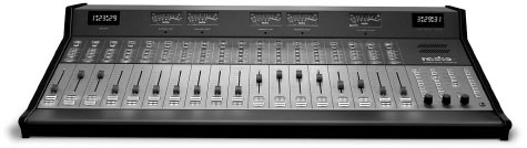
FIGURE 5.2 Some digital audio consoles feature a self-contained, modular architecture, much like older analog boards. (Image courtesy of Radio Systems.)

FIGURE 5.3 Audio boards found in recording studios and some production facilities are often more complex and have more features than basic audio consoles. (Image courtesy of AMS Neve.)
There are several options for digital audio console design. Some boards emulate traditional audio consoles and are self-contained units, as shown in Figure 5.2. The various audio sources are fed directly into the stand-alone console, which follows the most common wiring practice and allows console replacement to be a simple matter of “pick up the old, drop down the new.” Other digital consoles are designed so that the “board” is merely an interface or control surface for an audio “engine” that can be installed in a rack in the studio or in an equipment room down the hall (see Figure 5.4). In this instance, the audio console works like the keyboard for your computer. The audio engine is essentially a router that accepts both analog and digital inputs with a capacity that usually exceeds even the largest analog board. Generally, analog inputs are converted to digital signals, and digital signals with different sample rates are synchronized at the audio engine.
Another feature of many digital audio consoles is the inclusion of a touch screen interface (review Figure 5.4) or similar type of LCD (liquid crystal display) window. Because digital boards can be so readily customized to individual users, such as assigning different sources to different channels, a visual display helps with programming the board setup and operating the console.
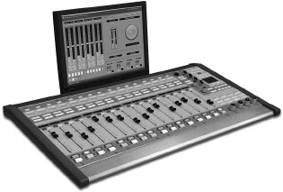
FIGURE 5.4 Many digital audio consoles are merely control surfaces that work in conjunction with a separate audio router that allows the electronics to be centralized in a rack or equipment room. (Image courtesy of Wheatstone Corporation.)
Any control board has three primary functions: mix, amplify, and route audio. First, the audio console enables the operator to select any one or a combination of various inputs. In other words, it must first be determined where the signal is coming from: a microphone, a CD player, or an audio recorder, for example. Audio consoles are sometimes referred to as “mixing boards,” because of their ability to select and have several inputs operational at the same time. Much of the production work you do will be a mix of voice, music, and sound effects through the audio console.
The second function of the control board is to amplify the incoming audio signal to an appropriate level. Although all sound sources are amplified to a degree, some sound sources (such as microphones) produce such a small electrical current that they must be further amplified to be used. What is also meant by “amplify” is that the volume of an audio signal going through the console can be raised or lowered. You’ll learn more about this level adjustment later in this chapter. The third function of the audio console is to enable the operator to route these inputs to a number of outputs, such as monitor speakers, the transmitter, or an audio recorder. This function allows the operator to determine where the signal is going and to provide a means for listening to the signal.
5.4 COMPUTERS AND AUDIO CONSOLES
Rather than having a physical audio board containing individual input and output modules with multiple controls, in some instances, the operator may simply manipulate a “virtual console” on a computer screen, as shown in Figure 5.5. This is common practice on digital audio workstations that include mixing functions and other audio software programs. Such virtual boards are often part of a digital audio storage and studio system, such as Broadcast Electronics’ AudioVAULT, which is a complete suite of software modules. The primary sections include a control screen for live or automated announcer operation and a waveform editor, and additional sections incorporate traffic and music scheduling, among other things. Other companies also offer computerized radio automation systems.
5.5 BASIC AUDIO CONSOLE COMPONENTS
All control boards, whether digital or analog, operate in basically the same way. For the purpose of simplicity, let’s consider a small audio console with just two channels. Figure 5.6 shows such a board. Each channel (M-1 and L-1) has two inputs (labeled A and B), so that, for example, a microphone could be assigned to channel M-1 (position A), and channel L-1 could have a CD player assigned to input A and an audio recorder assigned to input B. In general terms, a channel refers to the path an audio signal follows. On an audio console, a channel refers to a group of switches, faders, and knobs that are usually associated with one or two sound sources (glance ahead to Figure 5.9). On the board in Figure 5.6, note the individual input selectors, output selectors, volume controls, and on/off switches associated with each individual channel. The cue, headphone, and studio monitor gain controls are associated with both channels, as are the VU meters.

FIGURE 5.5 “Virtual” audio console controls emulate the functions of the traditional audio board. (Image courtesy of Arrakis Systems, Inc.)
The input selectors on this particular audio console are pushbuttons that can be put in either an A or B position. This feature allows two different sound sources to be associated with each channel. Although channel M-1 and channel L-1 look identical, there is a major difference between them. Channel M-1 has been designed to accept only microphone-level inputs. Microphones generally do not have amplifiers built into them, whereas CD players and audio recorders have already put their signals through a small amount of amplification. When a signal from a sound source comes into channel M-1, it is sent through a preamplification stage that is not present for signals coming into channel L-1. In other words, a microphone-level input allows a signal to catch up to a stronger signal coming into the line position in terms of amplification. Then both signals often go through additional amplification.
The way the input selector switches in Figure 5.6 are arranged, a microphone comes into the M-1 channel (A input), a CD player comes into the L-1 channel (A input), and an audio recorder comes into the L-1 channel (B input). Nothing is assigned to the B input of channel M-1. Wiring the equipment to the board involves running a cable from the microphone, CD player, and audio recorder to the back (or bottom) of the audio console. Such wiring is usually done in a semipermanent-to-permanent way by the engineer and should not be tampered with by others.

FIGURE 5.6 A simple two-channel audio console.
Not all audio boards have input selector switches. Some radio production boards have only one input per channel that must be at the microphone level, or other inputs that can only accommodate equipment that has been preamplified and is ready for a line level. On boards of this type, usually only microphones can be patched into the first two inputs, and only CD players, audio recorders, and other line-level equipment can be patched into the remaining inputs.
On the other hand, some boards have input selector switches that have three or more positions for one input. For these boards, it’s possible to patch a CD player at position A, another CD player at position B, and an audio recorder at position C all into the same input. The use that the facility is going to make of the various pieces of equipment has to be carefully studied, because of course no two pieces of equipment could be used at the same time on a single channel. Regardless of the configuration of an audio board, the first two channels (from the left) are often utilized as microphone-level channels. Channel 1 is normally the main studio microphone, and channel 2 is often an auxiliary microphone.
Digital audio consoles are changing the concept of input selection somewhat. Most digital boards allow the user to assign any audio source to any channel using a type of audio router, as shown in Figure 5.7. In other words, the console configuration can be personalized for each individual user, so that channel 3 can be associated with a CD player for one person, an audio recorder for another person, and a microphone for the next person. Once the source is selected for any of the console’s channels, the source name is usually displayed on an alpha display for that channel module.
The input volume controls shown in Figure 5.6 are called sliders, or faders. They are merely variable resistors. Although they are called volume controls, or gain controls, they don’t really vary the amount of amplification of the signal. The amplifier is always on at a constant volume. Raising the fader (moving it from a south to a north position) decreases the amount of resistance to this signal. When the fader is raised and the resistance is low, a great deal of the signal gets through. The dynamic is like that of a water faucet. The water volume reaching the faucet is always the same, even when the faucet is closed. When you open the faucet (decrease the resistance), you allow the water to flow, and you can vary that flow from a trickle to a steady stream.

FIGURE 5.7 On most digital consoles, any available audio source can be assigned to any one of the console’s input channels. (Image courtesy of Wheatstone Corporation.)
Some older boards have rotary knobs called potentiometers, or pots, instead of faders, although these are getting harder and harder to find. Pots provide the same function as faders. As the knob is turned clockwise, the resistance is decreased and the volume is increased. Most production people consider the fader to be easier to work with. For one thing, the fader gives a quick visual indication of which channels are on and at what level which is much harder to see with a rotary knob.
The numbers on both rotary knobs and faders may be in reverse order on some audio consoles to show their relationship to resistance. For example, if a knob is turned completely counterclockwise, or off, it may read 40; at a 12 o’clock position, it may read 25; and completely clockwise, it may read 0. These figures represent decreasing amounts of resistance and thus higher volume as the knob is turned clockwise. Modern boards with fader volume controls often use a range of numbers from 255 to 0 to 110 or 115. Although the same relationship to resistance is true (the more the fader is raised, the less resistance), these numbers actually relate to decibels and the VU meter. If the board has been set up properly, the 0 setting on the fader will produce a 0 reading on the VU meter (see Figures 5.10 and 5.11). Some boards avoid using any numbers at all and merely use equally spaced indicator lines to provide some kind of reference for various knob and fader settings.
Of course, most boards have more than the two channels of our example board. In most production studios, boards have 10 to 20 channels, but there are smaller and larger boards. Each channel has its own gain control and with two inputs per channel, more than 30 individual pieces of audio equipment can be manipulated through the console. In professional audio production facilities, consoles with more than 20 channels are not uncommon. With the digital board’s ability to assign various sources to channels, the trend is for smaller boards, as you usually work with only two to four channels active at any one time.
In addition to the gain controls just mentioned, some boards have a gain trim, or trim control, that fine-tunes the volume of each input. For example, if the sound signal coming from a CD player has the left channel louder (stronger) than the right channel, a stereo trim control can decrease the left level or increase the right level until the sound signal is equal for both channels. Each input channel on an audio console usually has a gain trim feature, and often there is a similar trim adjustment for the program and audition output of the audio board. Although these trim controls (sometimes referred to as “pad”) may be on the face of the audio board, they are more often an internal adjustment that is taken care of by the engineer when the control board is initially set up.
5.8 MONITORING: SPEAKERS AND HEADPHONES
Once the signal is through the input gain controls, it’s amplified in a program amplifier and then sent several places (see Figure 5.8). One of these is a monitor amplifier. This amplifies the signal so that it can be sent into a monitor speaker to enable the operator to hear the signal that is going out. Boards usually contain a simple potentiometer to control the gain of the monitor speaker. For instance, our example board has a pot labeled STUDIO, which controls the volume of the monitor speakers. This control in no way affects the volume of the sound being sent out to an audio recorder (or transmitter, for example). It controls only the volume for the person listening in the control room. In a broadcast application, the on-air monitor presents the actual output of the station after it has been broadcast. In a true broadcast situation, you must monitor the actual air signal. If you are only listening to the system’s program signal, you would not be aware if the signal goes off the air. In a production environment, the studio monitors are speakers used to hear what is routed through designated channels on the console. A common mistake of beginning broadcasters is to run the studio monitors quite loud and think all is well, while in reality they have the signal going through the audio board (and therefore to a recorder or on the air) at a very low level. It’s important for the operator to be aware of the level of sound going out the line, which is discussed regarding VU meters in section 5.10.
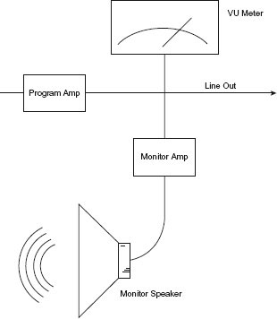
FIGURE 5.8 A block diagram of the monitor amplifier section of an audio console.
Most audio consoles also have a provision for listening to the output of the board through headphones. Because live microphones are often used in production work, the monitor speakers are muted when the microphone is on so that feedback doesn’t occur. To be able to hear an additional sound source, such as a CD, headphones are necessary. Audio consoles often allow you to monitor any of the outputs with headphones by selecting an appropriate switch. There is usually a volume control to adjust the signal level going to the headphones. On our example board, this control is labeled HDPN. As such, headphones allow one to hear all sound sources, be it in production or on-air, when the studio or control room microphone is engaged.
Another function found on most audio boards is called cue, which allows you to preview an input sound source. Both rotary pots and fader controls go into a cue position, which is below the off position for that control. If you turn the rotary pot all the way counterclockwise to off, it will reach a detent, or stop. If you keep turning the knob (with a little extra pressure), it will click into the cue position. Faders are brought down, or south, until they click into cue (see Figure 5.6 again). Some faders can be put into cue with a separate push button (see Figure 5.9) that, when depressed, puts that channel into cue regardless of where the fader control is set. Cue position is usually marked on the face of the audio console.

FIGURE 5.9 Whether digital or analog, a single channel of an audio console consists of a group of switches, pushbuttons, and a fade that can be used to manipulate a sound source that is assigned to that channel. (Image courtesy of Wheatstone Corporation.)
In the cue position, the audio signal is routed to a cue amplifier and then to a small speaker built into the control board. As the quality of this small internal speaker is usually marginal at best, the cue signal is often sent to a small, but better quality, external speaker located near the audio console. Some audio consoles send the cue signal to the main studio monitor speakers or may be monitored by headphones. The program signal is automatically turned down, or dimmed, when a channel is put into cue and the cue signal is heard on top of the program signal. On our example audio console, the cue volume level is controlled with the pot labeled CUE.
As the name implies, this position is designed to allow the operator to cue up a sound source. For example, an audio recording can be cued to the exact beginning so that the sound will start immediately when the recorder is turned on. If an input is in cue, the signal doesn’t go to any other output such as the transmitter or an audio recorder. Its only purpose is to allow off-air cueing. Many beginning announcers and production people forget to move the volume control out of the cue position after cueing up the sound source. If the control is left in the cue position, the signal won’t go out on the air or be routed to an audio recorder. It will play only through the cue speaker.

FIGURE 5.10 The standard VU meter incorporates both a percent and decibel scale.
Another place the signal is sent after program amplification is the volume unit indicator, or VU meter (see Figure 5.10). This is a metering device that enables the operator to determine what level of sound is going out the line.
One common type of VU meter has a moving needle on a graduated scale. Usually the top position of the scale is calibrated in decibels (dB), and the lower portion of the scale is calibrated in percentages. In audio engineering, a reading of 0 dB is 100 percent volume, or the loudest you want the signal to go. The VU meter is important for consistent audio production work. As noted in Chapter 2, “The Studio Environment,” how loud something sounds is very subjective. What is loud to one announcer may not be deemed loud by another, especially if they each set the monitor speaker volume differently. The VU meter gives an electronic reading of volume that is not subjective.
The accuracy of VU meters is sometimes questioned in two areas. First, VU meters have trouble indicating transients—sudden, sharp, short increases in volume of the sound signal. Most VU meters are designed to indicate an average volume level and ignore these occasional sound bursts. Second, VU meters tend to overreact to the bass portion of the sound. In other words, if a sound signal is heavy in the bass frequencies, it will probably show a higher VU reading than it would if the total sound signal were being accurately read. In spite of these concerns, the VU meter remains the best indicator of volume levels in broadcast production.
Generally, an operator should control the signal so that it stays approximately between 80 percent and 100 percent. When the needle swings above 100 percent, we say the signal is peaking in the red because that portion of the VU meter scale is usually indicated with a red line. This is a warning to the operator to lower the gain with the fader or pot because the sound is overmodulated. Digital equipment is very unforgiving in regard to recording “in the red.” Most digital equipment will not tolerate recording at any level above 100 percent and will distort or add “pops” to any recorded signal that exceeds it. Analog equipment is more forgiving in that it simply distorts sound, but good production practice dictates recording everything below 100 percent.

FIGURE 5.11 VU meters with fluorescent or liquid crystal displays can indicate volume changes more quickly and accurately than electromechanical meters. (Image courtesy of Dorrough Electronics.)
Often there is a metal peg at the far end of the VU meter to prevent the needle from going off the dial. Allowing the gain to become so high that the needle reaches the upper peg is called pegging the meter, or pinning the needle, and should be avoided to prevent damage to the meter as well as distortion of the signal.
When the signal falls below 20 percent consistently, we say the signal is undermodulated or in the mud, and the operator should increase the volume. If it’s necessary to adjust the level during the program, we say that the operator is riding the gain or riding levels. “Gain” is an audio engineer’s term for loudness or volume. This is why a radio operator was first called a disc jockey. He would play record “discs” and “ride” the gain.
Our example audio board (Figure 5.6) has a set of VU meters that indicates the left and right volume of the program sound going out and another set of meters that shows the audition output. Most boards have multiple VU meters. For example, they might have separate meters for each individual channel. Boards that have multiple outputs also have multiple meters. For example, a board that is stereo, like our example board, will have one meter for the right channel and one for the left.
On some boards, the VU meter isn’t an electromagnetic meter at all, but is rather a succession of digital lights (LEDs, or light-emitting diodes) that indicate how high the volume is. Other electronic meters (see Figure 5.11) replace the LEDs with liquid crystal or fluorescent displays; the advantage of these over mechanical meters is that they can indicate volume changes more quickly and accurately.
The most common arrangement for the output selectors on an audio board is a bank of three buttons for program, audition, and auxiliary outputs. The example board in Figure 5.6 has this type of configuration except the auxiliary output is labeled UTL for utility. When no button is pushed in, the output is stopped at this point. When the program button (PGM) is pushed, the signal normally goes to the transmitter if the board is in an on-air studio, or to an audio recorder if the console is in a production room. The program position would be the normal operating position when using an audio console.
If the audition button (AUD) is depressed, the signal is sent to an audition amplifier and can then be sent to the monitor speakers, an audio recorder, another studio, and so on. The audition signal will not normally be sent to the transmitter. The purpose of the audition switch is to allow off-air recording and previewing of the sound quality and volume levels of a particular signal. For example, you could be playing a CD on one CD player through channel 3 of the audio console (in the program position) and at the same time be previewing another CD on a different CD player through channel 4 in the audition position. Each channel of the audio console can be used either in the program or audition position.
The auxiliary (AUX) or utility (UTL) position is just like either the program or audition position and is another output for the audio board (see Figure 5.6). For instance, some studios are set up so that the auxiliary position of one control board feeds another studio and becomes an input on the audio console in the other studio. Such as the news booth sending a feed to the on-air studio. Unlike most input selectors, which allow only one input to be selected at a time, output selectors usually allow more than one output to be active. If all output buttons were depressed, you could send the same audio signal to three different locations at the same time.
The configuration of output selector buttons varies from board to board. If there are a large number of outputs—six, for example—then there may be six output buttons for each input. The input signal will be sent to whichever buttons are depressed, or selected. Sometimes there are no output selectors; every input either goes out or it doesn’t, depending on the master volume control. Other boards have buttons labeled SEND that determine where the signal goes. Some boards just use a single toggle switch in place of push buttons. The functions are exactly the same, depending on which way the toggle is switched, for example, program or audition. Typically, if the toggle is in the middle, or neutral position, the signal stops at that point (just like having no button pushed in a three-button bank).
It helps to distinguish between the basic radio board from consoles with input and output channels used in professional sound studios. Audio consoles are often referred to by their number of inputs and outputs, so a 16-in/4-out console has 16 inputs and 4 outputs. These are called multi-channel consoles (as in Figure 5.3) and have two definitive sides: input and output. The basic stereo board, such as those often found in radio broadcast studios (see Figure 5.2), are not multi-channel consoles since all inputs are sent to an established left and right stereo output.
There is no output volume control on our example board in Figure 5.6 that can be adjusted by the operator. Some audio consoles include a master fader that controls the volume of the signal leaving the board. Even if an input sound source is selected, program output is selected, and fader volume is up, if the master fader is all the way down, no signal will go from the console. Many boards have more than one output gain control. Again, a stereo board requires two masters: one for the right channel and one for the left. If there are multiple volume controls, then there’s usually a master gain control that overrides all the other output volume controls. In other words, if the master is down, the signal won’t go anywhere, even though one or more of the output volume controls are up.
5.13 REMOTE STARTS, CLOCKS, AND TIMERS
Other bells and whistles that frequently appear on audio boards include remote start switches (see Figures 5.6 and 5.9). These are usually located below each individual channel fader, and if the equipment wired into that channel (such as a CD player or audio recorder) has the right interface, it can be turned on, or started, by depressing the remote start. This makes it easier for the operator to start another sound source while talking into the microphone without having to reach off to the side and possibly be pulled off microphone. For most consoles, these switches also turn that channel on and off. In other words, even if you have the fader for that channel turned up, no sound signal will go through the channel until it has been turned on. However, some consoles are set up so that they will automatically turn the channel on when the fader is moved upward.
Many control boards include built-in clocks and timers. Digital clocks conveniently show the announcer the current time (hours, minutes, and seconds), and timers (see Figure 5.6) can be reset at the start of a CD to count up the elapsed time or count down the remaining time. Many timers will begin automatically when an “on” or remote start button is pressed.
Many sound boards include simple equalizers. These increase or attenuate certain frequencies, thus altering the sound of the voice or music by changing the tonal quality of the sound. In some instances, they help eliminate unwanted sound. For example, an audio recording might include an electronic hum that could be lessened by filtering out frequencies around 60 Hz. Equalizers can also be used for special effects, such as making a voice sound like it is coming over a telephone. It’s important to note that when you equalize a sound, you can affect both the unwanted and wanted sound; equalization is often a compromise between eliminating a problem and keeping a high-quality, usable audio signal.
Usually the equalizers are placed somewhere above each input volume control. In Figure 5.9, the input signal of the analog channel is split into three frequency ranges: high, midrange, and low. Turning the control clockwise increases the volume of that range of frequencies; counterclockwise rotation of the control will decrease its level. The “EQ in” button on this channel is actually a bypass switch that allows the operator to hear and compare the signal with and without equalization. Equalizers and other similar equipment will be discussed in further detail in Chapter 8, “Signal Processing Equipment.”
Audio console channel inputs that are stereo often have a pan knob, or pan pot. By turning (panning) this knob to the left or right, you can control how much of the sound from that input goes to the right channel and how much goes to the left channel output. In other words, if the pan pot of a channel is turned toward the L position, the level would sound stronger, or louder, from the left speaker. Normally, the pan pot would be in the center position and the input sound would be directed equally to the left and right outputs of that channel. Monaural input channels may have a balance control, which serves a similar purpose.
Some boards have a built-in tone generator. This reference tone is usually placed on an audio recording before the actual program material begins. The tone generator sends out a tone through the board that can be set at 100 percent, using the board VU meter. The VU meter on the source to which the signal is being sent (such as an audio recorder) is simultaneously set at 100 percent. After the two are set, any other volume sent through the board will be the exact same volume when it reaches the recorder. A tone generator allows for this recording consistency; otherwise, sounds that register at 100 percent coming through the board might peak in the red and be distorted on the audio recorder. The tone on the recording is also used during playback. The audio engineer or board operator listens to the tone and sets the recorder VU meter to 100 percent. That way the recording will play back exactly as it was recorded.
Some audio consoles have a solo switch above each input. When this switch is on, only the sound of that particular input will be heard over the monitor. Other boards have a mute switch for each channel, which prevents the signal from going through that channel when it’s depressed. A mute switch acts just like an on/off switch.
A few boards have a talk-back switch, which is a simple intercom system consisting of a built-in microphone and a push-button control that turns the microphone on or off. The normal position of this switch is “off” so that the button must be pushed in to activate the microphone. The signal from the talk-back microphone is sent to a speaker or headphones in another studio—for example, a performance studio—which would allow the operator at the audio console to communicate with the announcer in a studio at a separate location.
PRODUCTION TIP 5A
Manipulating Faders
The type of transition that you are planning to have can affect how you are operating the faders of your board. If you know you will be doing a segue (explained shortly), you can set the fader levels for the new sound you will be bringing in ahead of time by using the audition function. Then, when it’s time to take out one sound and bring in the other, you can simply hit the appropriate off and on buttons below the faders. That way you don’t need to be concerned about getting the fader to the right position in order to have the new sound at the right level.
Working with the on/off buttons instead of the faders is also a good idea if you are doing a program where people are speaking. You can set the faders for each person’s speaking level ahead of time and then, when the program begins, you can just push the “on” buttons and all the levels will be correct. This mode of operation is also advantageous if you are both talking and playing music. Set your microphone level ahead of time and then each time you will be talking, you can simply push the “on” button and not have to look down to make sure you have set the fader in the right position.
Of course, if you need to do a fade-in, fade-out, or cross-fade, this method won’t work. For these transitions, you will want to have the “on” buttons already pushed and then bring the faders up or down to execute the fade.
5.16 SOUND TRANSITIONS AND ENDINGS
As mentioned earlier in this chapter, one of the functions of the audio console is to mix two or more sound sources together. Often this mix is really a sound transition, or the merging of one sound into another. In audio production, one basic transition is the fade (gradually increasing or decreasing volume), in which you mix one sound with silence. For example, to fade-in a CD means to slowly increase the volume from silence to the desired level (see Figure 5.12A). A fade-out accomplishes just the opposite, as the CD goes from full volume to silence (see Figure 5.12B). Most compact discs are recorded so that they fade out at the end naturally, but in production work it’s sometimes necessary to end a song early, and the production person can do so with a manual fade-out. Conversely, to allow a piece of music to have a natural ending, it is sometimes necessary to fade in after the music has started. This is known as a “dead roll,” since the music is started with the fader down.

FIGURE 5.12 Sound transitions are used frequently in audio production work.
The other common transitions are the cross-fade and segue. As the name implies, a cross-fade occurs when one sound is faded down as another sound is faded up (see Figure 5.12C). There is a point as the two sounds cross when both sounds are heard. Because of this, care should be taken in choosing music to cross-fade. Some combinations of songs can sound extremely awkward. The speed of a cross-fade is determined by the board operator and depends on the type of effect desired; however, most cross-fades are at a medium speed to give a natural, brief blending of the two sounds. A segue is quite different; it is the transition from one sound to the next with no overlap or gap (see Figure 5.12D). A segue can best be accomplished when the first song ends cold. Music with a cold ending doesn’t fade out, but rather it has a natural, full-volume end. Unlike fades of any kind, segues are accomplished with both sounds at full volume. Most disc jockey work is a mixture of cross-fades and segues, but all the sound transitions are used frequently in audio production work.
In addition to the fade-outs and cold endings, one other music ending that should be noted is the sustain ending. Songs with a sustain ending will hold the final chord or notes for a short period of time and then very gradually fade out. This is distinctly different from either a normal fade-out or a cold ending.
If you have followed the descriptions and explanations offered in this chapter, the audio console should be a less frightening assemblage of switches, knobs, and meters than it was when you began. You should begin to feel comfortable working with the controls of the board in your own studio. You should also be aware that most modern audio consoles will be a digital board or it may be a virtual audio console that you maneuver with a few mouse clicks or a touch screen.
1. It’s possible to have music from an audio recorder go into a control board and then come out and be recorded on another recorder.
a) true
b) false
2. In Figure 5.9, according to the pan pot position on the analog channel, what is the relationship between the sound signal going to the left channel and the signal going to the right channel?
a) Left channel volume would be less than right channel volume of the same signal.
b) Left would be the same as right (similar change).
c) Left would be greater than right (similar change).
d) There would be no signal going to the right channel.
3. If the digital fader in Figure 5.9 was at 3 and you moved it to 7, what would you have accomplished?
a) amplified the signal
b) put the channel in cue
c) decreased the resistance
d) decreased the volume
4. In Figure 5.6, sound on channel L-1 would not get to program out to be broadcast or recorded unless what happened?
a) The fader is at 0.
b) The PGM output selector switch is on.
c) The HDPN volume control is at 3.
d) The A input selector switch is set to CD.
5. Audible sound comes from what in Figure 5.8?
a) the VU meter
b) the monitor amplifier
c) the program amplifier
d) the monitor speaker
6. In Figure 5.10, a reading of 50 percent on the scale is roughly equivalent to which reading on the dB scale?
a) –6 dB
b) –4 dB
c) 50 dB
d) –10 dB
7. Which expression describes a 20 percent reading on the VU meter in Figure 5.10?
a) peaking in the red
b) turning up the pot
c) being in the mud
d) riding the gain
8. Which expression describes a 3-dB reading on the VU meter in Figure 5.10?
a) riding the gain
b) broadcasting in stereo
c) peaking in the red
d) pegging the meter
9. A line-level channel of an audio console would have what type of equipment assigned to it?
a) CD player and audio recorder
b) microphone and CD player
c) microphone and audio recorder
d) only microphones
10. Which choice most accurately describes the monitor/speaker?
a) an input
b) a mix
c) an output
d) an equalizer
11. Look at Figure 5.6. What happens if the PGM/AUD/UTL output selector switch of channel M-1 is in the audition position?
a) Sound will not reach the input A switch.
b) Sound can be going to an audio recorder.
c) Sound can be going to the transmitter.
d) Sound will go to the cue speaker.
12. Which statement about the master volume control on an audio board is true?
a) must be up for sound to leave the board
b) is required only if the board is stereo
c) controls only the volume of the line inputs
d) controls only the volume of the microphone inputs
13. Which control found on an audio console might be used to help eliminate electronic hum on an audio recording?
a) the pan knob
b) the gain trim
c) the solo button
d) the equalizer
14. Which statement about the cue position on a fader is true?
a) allows sound to go to the transmitter
b) sometimes substitutes for the trim control
c) sends sound to a small speaker in the audio board
d) allows sound to fade from the left to right channel
15. Which of the following can help assure that the level that’s being recorded on an audio recorder is the same as that coming from the audio board?
a) tone generator
b) remote switch
c) digital timer
d) pan pot
16. Which of the following statements about digital audio consoles is not true?
a) Digital consoles are more expensive than analog consoles.
b) Digital consoles include some type of display screen.
c) Digital consoles do not accept analog inputs.
d) Digital consoles offer several design architectures.
17. Which sound transition occurs when one CD is faded down at the same time as another CD is faded up?
a) fade-in
b) fade-out
c) segue
d) cross-fade
18. On an audio console, which term refers to a group of switches, faders, and knobs that are usually associated with one sound source, such as a CD player?
a) input selector
b) remote start switch
c) channel
d) output selector
19. A segue is the basic sound transition in which one sound is mixed with silence.
a) true
b) false
20. Most audio consoles used in radio broadcasting are identical to the consoles used in music recording.
a) true
b) false
21. Which feature of an audio console would allow the operator to alter the tonal quality of a sound going through the board?
a) mute switch
b) gain trim control
c) equalizer control
d) talk-back switch
22. How can a channel of the digital audio console shown in Figure 5.9 be put into cue?
a) by moving the fader up to 0
b) by moving the fader down to 7
c) by depressing the START button
d) by depressing the CUE button
23. Which feature of an audio console is a simple intercom system?
a) talk-back switch
b) tone generator
c) pan knob
d) output selector
24. On an audio console, a pan pot and a balance control both serve a similar function.
a) true
b) false
25. If you were attempting to segue from one song to another, how should the first song end?
a) fade-out
b) cold ending
c) fade-in
d) sustain ending
If you answered A to any of the questions:
1a. Right. A tape recorder can be both input and output and an audio console can link two recorders.
2a. No. Check the setting of the pan pot. (Reread 5.14.)
3a. No. The fader never actually amplifies the signal. This is done with preamp or amplifier circuits. (Reread 5.7.)
4a. No. When a fader or pot is at 0, it is usually on. (Reread 5.7 and 5.11.)
5a. No. This indicates level, but you hear nothing from it. (Reread 5.8 and 5.10.)
6a. Right. You read the scale correctly.
7a. No. The needle would be at the other end of the scale for this. (Reread 5.10.)
8a. No. “Riding the gain” means to keep the volume at proper levels, and this is not being done. (Reread 5.10.)
9a. Correct. Both a CD player and an audio recorder are line-level inputs.
10a. No. You’re at the wrong end. (Reread 5.3, 5.5, and 5.8.)
11a. No. The input selector switch is before the output selector switch and really has nothing to do with it. (Reread 5.6 and 5.11.)
12a. Right. The purpose of the master volume is to allow all appropriate sounds to leave the audio console.
13a. No. This controls how much sound is going to the left and right channels. (Reread 5.14.)
14a. No. When a channel is in cue, sound will not go to the transmitter. (Reread 5.9.)
15a. Right. If the board VU meter and the tape recorder VU meter are both set at 100 percent tone, the levels should be the same.
16a. No. Although the difference between the price of an analog board and a digital console is becoming less and less, many digital boards are slightly more expensive than their analog counterparts. (Reread 5.2.)
17a. No. This is a different sound transition. (Reread 5.16.)
18a. No. This is one of the switches involved, but this is not the correct term. (Reread 5.5 and 5.6.)
19a. No. You’ve confused this with the fade. (Reread 5.16.)
20a. No. Although there are similarities between all audio consoles, those most often found in radio are more basic than those used in the music recording studio. (Reread 5.1.)
21a. No. This control turns off a console channel. (Reread 5.14 and 5.15.)
22a. No. This will turn the volume of the channel up. (Reread 5.7 and 5.9.)
23a. Correct. The talk-back feature allows a board operator to talk with an announcer in another studio via a simple intercom system.
24a. Yes. Both can be used to adjust how much of the audio signal goes to either the left or right channel output.
25a. No. A segue should happen with both songs at full volume with no overlap or silence between songs; if the first song fades out, this won’t happen. (Reread 5.16.)
If you answered B to any of the questions:
1b. Wrong. A tape recorder can be fed into an audio console and another tape recorder can be placed at the output. (Reread 5.3 and 5.5.)
2b. No. Check the setting of the pan pot. (Reread 5.14.)
3b. No. Cue would be even below the “infinity” mark. (Reread 5.7 and 5.9.)
4b. Right. When the PGM output selector switch is in the “on” position, normally sound would be sent to the transmitter or an audio recorder.
5b. No. This amplifies so that the sound can come out, but you don’t hear the sound from it. (Reread 5.8.)
6b. No. You went in the wrong direction. (Reread 5.10.)
7b. No. If anything, the pot is being turned down. (Reread 5.10.)
8b. No. This is not correct. (Reread 5.10.)
9b. No. A microphone should come into a microphone input, because it needs to be amplified to reach the line level of amplification. A CD player would be plugged into the line position. (Reread 5.3 and 5.6.)
10b. No. This is incorrect. (Reread 5.3, 5.5, and 5.8.)
11b. Yes. The purpose of the audition position is to send the sound somewhere other than the transmitter. Sound would not necessarily have to go to an audio recorder, though it could.
12b. No. A master volume control functions the same for both mono and stereo. Stereo boards, however, usually have two master volume controls, one for each channel. (Reread 5.12.)
13b. Wrong. This allows fine-tuning of input or output levels on an audio board. (Reread 5.7 and 5.14.)
14b. No. The two have nothing to do with each other. (Reread 5.7 and 5.9.)
15b. No. This will turn on the recorder remotely but will do nothing about levels. (Reread 5.13 and 5.15.)
16b. No. Whether it’s a simple alpha display on the channel module or a full LCD screen, because they can be readily reconfigured, all digital boards have some type of display screen. (Reread 5.2.)
17b. No. This is a different sound transition. (Reread 5.16.)
18b. No. This is one of the switches involved, but this is not the correct term. (Reread 5.5 and 5.13.)
19b. Correct. The basic sound transition that mixes one sound with silence is the fade, not the segue.
20b. Yes. This is false, because radio consoles are usually not as complex as the boards used in music recording.
21b. Wrong. This control varies the input level of a sound source of a console channel. (Reread 5.7 and 5.14.)
22b. No. Although some consoles are put into cue by moving the fader down, it would have to go all the way down and usually “click” into a cue position. (Reread 5.7 and 5.9.)
23b. Wrong. The tone generator provides a reference level for setting correct recording levels. (Reread 5.15.)
24b. No. This is not false because both controls can be used to adjust the amount of audio signal that is sent to the left or right output. (Reread 5.14.)
25b. Yes. The first song should have a cold ending if you’re going to segue into the next song.
If you answered C to any of the questions:
2c. Right. The pan pot is set so that more of the sound from the input goes to the left channel.
3c. No. Changing the level from 3 to 7 would increase resistance. (Reread 5.7.)
4c. Wrong. The HDPN volume control only controls the volume of the headphone’s audio. (Reread 5.8 and 5.11.)
5c. No. This amplifies sound, but you don’t hear sound from it. (Reread 5.8.)
6c. There is no such reading on a VU meter. (Reread 5.10 and review Figure 5.10.)
7c. Right. “In the mud” is the term for an extremely low reading.
8c. No. It is worse than that because the needle is all the way to the end of the scale. (Reread 5.10.)
9c. No. A microphone should come into a microphone input because it needs to be amplified to reach a usable level. An audio recorder would be plugged into the line position. (Reread 5.3 and 5.6.)
10c. Right. Sound comes out to the monitor/speaker.
11c. No. The audition position is not normally used to send the sound to the transmitter. (Reread 5.11.)
12c. No. It controls all the sound that is set to leave the board. Line and microphone positions have no bearing on it. (Reread 5.6 and 5.12.)
13c. No. This allows you to hear one input channel by itself. (Reread 5.14 and 5.15.)
14c. Right. Cueing is just for the person operating the board.
15c. No. This is simply a type of clock. It has nothing to do with levels. (Reread 5.13 and 5.15.)
16c. Yes. Digital boards have modules that accept analog signals and convert them to digital.
17c. No. This is a different sound transition. (Reread 5.16.)
18c. Yes. This is the correct term.
21c. Right. EQ controls increase or decrease certain frequencies of the sound, thus changing the tone.
22c. No. If the fader was up, this would let us hear audio, but not in cue. (Reread 5.9 and 5.13.)
23c. Wrong. Pan pots control the amount of sound that goes to the left or right output of a channel. (Reread 5.14 and 5.15.)
25c. No. You’re confused here; a fade-in isn’t a way a song ends. (Reread 5.16.)
If you answered D to any of the questions:
2d. No. That would not be correct. (Reread 5.14.)
3d. Right. This is an increase in resistance to the signal; not as much of the signal gets through, and it’s at a lower volume.
4d. Wrong. It wouldn’t matter if you assigned the A input to a CD, audio recorder, or some other piece of equipment. (Reread 5.6 and 5.11.)
5d. Right. You hear sound from the monitor speaker.
6d. You might be thinking of half of the dB scale, but that isn’t correct. (Reread 5.10.)
7d. No. If anything, the operator is not properly riding the gain. (Reread 5.10.)
8d. Right. “Pegging the meter” is correct. We could also have used the term “pinning the needle.”
9d. Wrong. Microphone signals must be amplified to reach line level and should only come into a microphone input. (Reread 5.3 and 5.6.)
10d. No. An equalizer affects frequencies. (Reread 5.3, 5.5, 5.8, and 5.14.)
11d. Wrong. The cue speaker will be activated when a channel is put into cue, regardless of where the PGM/AUD/UTL switch is. (Reread 5.9 and 5.11.)
12d. No. It controls all the sound that is set to leave the board. Microphone and line positions have no bearing on it. (Reread 5.6 and 5.12.)
13d. Right. This can help eliminate high frequencies where scratches reside.
14d. No. You’re confusing this with a pan pot. (Reread 5.9 and 5.14.)
15d. No. This allows sound to fade from the left to right channel. (Reread 5.14 and 5.15.)
16d. Wrong. Digital boards have more than one design approach, for example, the mainframe and control-surface system. (Reread 5.2.)
17d. Yes. This is the correct response.
18d. No. This is one of the switches involved, but this is not the correct term. (Reread 5.5 and 5.11.)
21d. Wrong. This control is a form of studio intercom. (Reread 5.14 and 5.15.)
22d. Yes. On this console, any channel can be put into cue merely by pressing the cue button associated with that channel, regardless of where other switches or buttons are set.
23d. Wrong. Output selectors determine where sound goes when it leaves the audio console. (Reread 5.11 and 5.15.)
25d. No. A segue should have no overlap or silence between songs; if the first song has a sustain ending, this won’t happen. (Reread 5.16.)
Learn to operate an audio console.
Purpose
To make you proficient operating some functions of the audio console, and to practice basic sound transitions.
Notes
1. Audio boards are generally one of the more complicated pieces of audio equipment. It may take you a while to master a board, but don’t despair. Take it slowly, and don’t be afraid to ask for help.
2. Audio boards all have the same general purpose. Sounds come into the board, are mixed together, and are sent out to somewhere else.
3. The actual exercise should be done rapidly. You won’t be judged on aesthetics. In other words, when you’re fading from one source to another, do it quickly. Don’t wait for the proper musical beat, phrase, or pause.
How to Do the Project
1. Familiarize yourself with the operation of the audio console in your production studio. Learn the inputs, the outputs, the method for changing volume, and other special features of the board.
2. As soon as you feel you understand the board, do the following exercise while recording it on an audio recorder. Practice as much as you like first.
a. Cue up a CD, play part of it, and fade it out.
b. Using the studio microphone, announce your name and the current time.
c. Begin a second CD.
d. Cross-fade to another CD, and then fade it out.
e. Bring in an auxiliary microphone, and ad-lib with another announcer.
f. Fade-in a CD, segue to another CD, and fade it out.
g. Announce something clever on the studio microphone.
3. Listen to your recording to make sure it recorded properly.
4. Label your recording “Audio Console Operation” and include your name. Hand the assignment in to your instructor to receive credit for this project.
Diagram and label an audio board.
Purpose
To familiarize you with the positioning of the various switches and controls so that you can access them quickly.
Notes
1. Some boards are very complicated and have more functions than are discussed in this chapter. Usually, this is because they’re intended to be used for sound recording of music. If you have such a board, you need to label only the parts that you will be using frequently.
2. If you can’t find controls for all of the functions given in this chapter, ask for help. Because there are so many different brands and types of boards, sometimes functions are combined or located in places where you can’t identify them easily.
3. You don’t need to label each switch and knob. If your board has ten inputs, it will obviously have ten channel-volume controls. You can circle them all and label them together, or make one label that says “Input Volume Controls” and draw arrows to all ten.
4. You will be judged on the completeness and accuracy of your drawing. You won’t be graded on artistic ability, but be as clear as possible.
How to Do the Project
1. Sketch the audio console in your production studio.
2. Label all the basic parts: input selectors, channel gain controls, VU meters, output selectors, and master gain controls (if your board has them).
3. Also label any other parts of the board that you will be using frequently, such as equalizers, cue positions, and headphone connections.
4. Label your sketch with your name and the title, “Audio Console Diagram.” Give your completed drawing to your instructor for credit for this project.
Record a two-voice commercial.
Purpose
To develop your skill in creating a spot while working with another announcer.
Notes
1. This project assumes that you have enough familiarity with your studio equipment to accomplish basic recording and production techniques.
2. The production incorporates two announcer voices and a music bed.
3. You will need to write a dialogue script that can be read in about 23 seconds. You might write copy about a restaurant you eat at frequently or some cosmetic or health product you are familiar with.
4. There are many ways to accomplish this project, so don’t feel you must follow the production directions exactly.
How to Do the Project
1. Record the script (voices only) onto an audio recorder. Make sure both voices are close to the same volume level. Rerecord to correct mistakes or just to get it to sound the way you want.
2. Select a music bed that is appropriate for the style of the spot. You might find something on the CD-ROM that accompanies this text.
3. You can play back the music bed directly from a CD, or you may have to record it on another recorder.
4. Set correct playback levels for both the vocal track and the music bed. Both will start at full volume. Then cue both to the beginning sound.
5. Record your completed spot onto a CD-R, so set your recorder to record mode. (Your instructor may advise you to record on different media.)
6. Begin recording. Start the music bed at full volume. Start the vocal track and simultaneously fade the music bed slightly so the vocal track is dominant.
7. As the vocal ends, bring the music bed back to full volume and then quickly fade it out as you approach 30 seconds.
8. It may take you several attempts to get the spot to come out correctly. If you need to do it over, just cue everything and try again.
9. Listen to the finished commercial. Make sure that you’ve gotten a good balance between the music and the voice and all recording levels are proper.
10. Label the assignment with your name(s) and “Two-Voice Radio Spot.” Turn it in to your instructor to receive credit for this project.