MICROPHONES
In audio production, microphones are used to record voice, music, or sound effects in both the studio and the field. The studio microphone (see Figure 4.1) takes on an important role, because it is usually the first element in the audio chain. It’s the piece of equipment that changes the announcer’s voice into an electrical signal that can then be mixed with other sound sources and either recorded, streamed, or broadcast. Because the purpose of the microphone is to change sound energy into electrical energy, it is known as a transducer, which is a device that converts energy from one form into another.

FIGURE 4.1 The studio microphone changes the announcer’s voice into an electrical signal. (Image courtesy of Neumann/USA.)
While digital microphones are becoming more common, most microphones are still analog-based. Putting an analog-to-digital converter in an external microphone preamplifier or immediately after the microphone in the audio chain, or within the microphone housing itself could quickly transform any microphone’s electrical output to a digital signal. For example, Audio-Technica’s AT2020 USB microphone, shown in Figure 4.2, has an analog-to-digital converter built into the housing, with a USB output for direct connection to a computer or digital recorder. Manufacturers including National Semiconductor and Akustia have developed integrated circuits that convert a microphone sound signal directly into a digital bit stream output signal, making for a truly digital microphone. It’s highly likely that we’ll continue to see more digital microphone developments in the future.
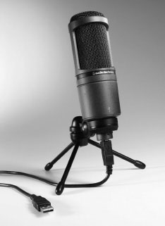
FIGURE 4.2 With a USB digital output, this microphone is ideal for computer-based recording. (Image courtesy of Audio-Technica U.S. Inc.)
This chapter looks at different types of microphones and some of their key characteristics. Selecting the wrong microphone for a particular situation can result in a poor recording that can’t be fixed with any postproduction processing. The astute audio production person takes advantage of a microphone’s qualities to achieve the best possible sound quality for either live broadcast or digital recording.
There is no one universal, standard microphone that will work in all recording situations. For example, a microphone that is perfect for voice-over work in the studio may not work well for recording a sound effect in the field. There are, however, specific types of microphones that work better than others in certain situations. Microphones are usually classified by two key characteristics—the way in which they convert sound into electrical current, and their pickup pattern. Generally speaking, there are two ways that microphones convert sound into electricity, and there are two types of pickup patterns. In both categories, there are some variations.
Some radio stations use a standard microphone throughout their facilities; however, the general audio production facility tends to take another approach, which is to have multiple types of microphones available. That makes sense, because it allows the facility to be flexible when handling a number of different recording situations.
The dynamic microphone refers to one way in which sound is converted into electricity. Commonly known as the moving-coil microphone or occasionally the pressure microphone, its sound-generating element is constructed of a thin, plastic diaphragm, a magnet assembly, and a voice coil, as shown in Figure 4.3. The flexible diaphragm, located near the head of the microphone, responds to the pressure of sound waves. The diaphragm is positioned so that the changes in pressure cause an attached small coil of wire to vibrate. This coil rests within the field of a permanent magnet, and movements of the diaphragm result in a disturbance of the magnetic field. This induces a small electric current into the coil of wire, which is the audio output signal.
The dynamic microphone is a good general-purpose microphone commonly used in radio and audio production studios. Because of its relatively simple construction, it is modestly priced, and produces very low noise with excellent frequency response (the accurate reproduction of both high and low frequencies). Another reason for its popularity is its sturdy design. The dynamic microphone can withstand a moderate amount of abuse, which often occurs in broadcast settings and in field production. Dynamic microphones can handle extremely high sound levels, which make it almost impossible to overload them, and they are not usually affected by temperature or humidity extremes. This style of microphone is also fairly insensitive to wind, and this feature, along with its ruggedness, makes it an excellent remote or field recording microphone.
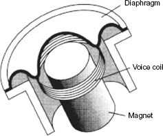
FIGURE 4.3 The internal components of a dynamic microphone include a diaphragm, magnet, and voice coil. (Image courtesy of Shure Incorporated.)
The main disadvantage of the dynamic microphone is that it has difficulty reproducing certain vocal characteristics. The microphone has a tendency to exaggerate plosives (popping on p) and sibilance (hissing on s or c). Dynamic microphones also can lose some light, delicate sounds, because the mass of the diaphragm requires a fairly high level of sound to move it, and even though the dynamic microphone is fairly rugged, all microphones are fragile to some extent and should be handled with care like any other piece of audio production equipment.
The other way in which a microphone changes sound into electricity is the condenser microphone. Sometimes referred to as a capacitor microphone, it uses an electronic component (a capacitor) to help transduce sound into electricity. The sound-generating element consists of a charged conductive diaphragm and an oppositely charged metallic backplate separated by an insulating material that creates an air space between them to form a sound-sensitive capacitor (see Figure 4.4). The thin metal or metal-coated plastic diaphragm responds to sound waves, changing the distance between the diaphragm and the backplate; this alteration changes the capacitance (the resistance to electrical voltage buildup) and generates a small electrical signal that is further amplified within the electronics of the microphone. This fluctuation of electrical current is the audio output signal.
A condenser microphone requires a power supply, sometimes a battery, to charge the backplate, the diaphragm, and related electronic components. Some condenser microphones utilize small internal power supplies or phantom power rather than a battery. Phantom power usually comes from a recorder or an audio console through the microphone cable and back to the microphone.

FIGURE 4.4 The internal components of a condenser microphone include two oppositely charged plates—a moveable diaphragm and a fixed backplate. (Image courtesy of Shure Incorporated.)
Because all condenser microphones are powered, the electronics of the microphone can produce a little noise, and there is a limit to the sound level that the microphone can handle. Still, the condenser microphone is an excellent choice, because it’s fairly rugged and produces excellent sound quality and wide frequency response. This microphone also has excellent transient response, but can be distorted at high recording volumes. Although the dynamic microphone is the most commonly used radio production microphone, the condenser microphone is also frequently found in the modern audio production facility. Built-in microphones on many portable audio recorders are often condenser microphones that provide fairly good quality on both consumer and professional models.
4.5 MICROPHONE PICKUP PATTERNS
In addition to categorizing microphones by the way they convert sound into electricity, they can also be classified by the direction in which they are most sensitive to sound, also known as their pickup patterns. Microphones are constructed so that they have different directional characteristics (Figure 4.5). Sound picked up at the front of the microphone, or at 0 degrees, is said to be on-axis. Sound picked up from the microphone’s side is 90 degrees off-axis, and sound picked up from the rear of the microphone is 180 degrees off-axis. A microphone’s housing, through the use of small openings and ports, can be designed so that unwanted sound (often off-axis sound) is canceled out or weakened as it enters the microphone. The on-axis sound received directly from the front of the microphone fully impacts the microphone’s diaphragm. An understanding of the microphone pickup patterns helps the user place the microphone in the best location relative to the sound source, in order to maximize the pickup of desired sound and minimize the pickup of unwanted background noise.

FIGURE 4.5 On-axis sound, picked up directly from the front of the microphone, fully impacts the microphone’s diaphragm.
The most common pickup patterns are omnidirectional and cardioid, but there are variations. Although most microphones will have one fixed pickup pattern, multidirectional microphones have switchable internal elements that allow the microphone to employ more than one pickup pattern.
4.6 THE OMNIDIRECTIONAL PICKUP PATTERN
The omnidirectional microphone is also known as a nondirectional microphone. These two terms may seem to contradict each other since omni means “all” and non means “no.” Both terms are correct, however, because this microphone picks up sound in all directions, but that also means that it has no particular pickup pattern. Think of a basketball with a microphone in the middle. No matter where the sound comes from around the basketball, the microphone responds to it equally well. Figure 4.6 illustrates the pickup pattern for a typical omnidirectional microphone.
Omnidirectional microphones are used whenever it is desirable to pick up sound evenly from all sides of the microphone, including above and below it. Omnidirectional microphones are commonly used outside the studio when the ambience of the location needs to be picked up along with a person’s voice. Of course, the fact that these microphones pick up sound equally well from all directions can also be a disadvantage. You may pick up unwanted background noise (such as traffic noise, air conditioner noise, or crowd noise) in addition to the voice you want to record. Omnidirectional microphones used in a highly reflective room may also produce a “hollow” sound, because they tend to pick up more reverb from the room than other types of microphones.

FIGURE 4.6 The omnidirectional pickup pattern shows that the microphone picks up sound equally well from all directions.
4.7 THE CARDIOID PICKUP PATTERN
The cardioid microphone picks up sound from mainly one direction—the front of the microphone. Its pattern is actually heart-shaped, hence the name cardioid (see Figure 4.7). Another way to visualize this pickup pattern is to think of an upside-down apple, where the stem represents the microphone and the rest of the apple approximates the cardioid pickup pattern. Although the microphone picks up sound from the front and sides, the level of pickup from the sides is only about half that of the front. The microphone doesn’t pick up sound well from the rear at all—less than one-tenth of the sound it can pick up from the front.
Variations on the basic cardioid design include super-cardioid, hyper-cardioid, and ultra-cardioid microphones. They continue to offer great rejection of sound from the sides, but each microphone also picks up a more narrow scope of on-axis sound. These microphones are even more directional in nature and are sometimes referred to as unidirectional. Cardioid microphones are very popular because they reject unwanted sounds (excessive reverb, feedback, background noise), but the talent must be careful to stay “on mic” and not move too far off-axis, especially when using super-, hyper-, or ultra-cardioid microphones.
Another microphone pickup pattern is the bidirectional microphone, which picks up sound from the front and the rear of the microphone, or on-axis and off-axis (see Figure 4.8). Its pickup pattern can be visualized as a figure 8, with the microphone located at the intersection of the two circles. It was often used for radio dramas so that actors could face each other, but it is not a common pickup pattern for most of today’s microphone use. It is, however, a good microphone for the basic two-person interview.

FIGURE 4.7 A cardioid pickup pattern shows that the microphone picks up sound mainly from the front and side, but not very well from the back.

FIGURE 4.8 The bidirectional pickup pattern shows that the microphone picks up sound from the front and back of the microphone.
Keep in mind that pickup patterns refer to the three-dimensional area around the microphone in which it best “hears” or picks up the sound. Figures 4.6, 4.7, and 4.8 are actually visual representations of a microphone’s polar pattern. Polar patterns are two-dimensional drawings or representations of a microphone’s pickup patterns, and are used mainly due to the difficulty of displaying three dimensions on a printed page. Compare the cardioid pickup pattern and polar pattern shown in Figure 4.9. This distinction is brought up here because although pickup patterns and polar patterns are technically different, in practice, the terms are often used interchangeably.

FIGURE 4.9 A three-dimensional view of the cardioid microphone pickup pattern alongside its two-dimensional polar pattern representation. (Three-dimensional image courtesy of Sennheiser Electronic Corporation.)
A polar pattern is drawn around a full circle, or 360 degrees. As noted earlier, the line from 0 to 180 degrees represents the microphone’s axis, and sound entering the microphone from the front (0 degrees) is on-axis. The concentric circles of a polar pattern show decreasing dB levels and allow us to see how the sound will be attenuated as it is picked up off-axis. For example, Figure 4.7 shows that sound picked up directly in front of the microphone will experience no attenuation or weakening. On the other hand, sound picked up from either side (90 degrees off-axis) will be attenuated by about 5 dB, and sound coming directly from the rear of the microphone (180 degrees) will be attenuated by almost 20 dB.
Another factor sometimes used to categorize microphones is impedance, a characteristic that is similar to resistance and common to audio equipment. Impedance is expressed in ohms, and microphones can be either high-impedance (10,000 ohms or higher) or low-impedance (600 ohms or less). Microphones that fall between the 600–10,000 ohm range are known as medium-impedance microphones. Most professional microphones are low-impedance, as they provide the best frequency response, and most professional audio equipment is designed to accept this type of microphone. High-impedance microphones are also quite limited in the length of microphone cable that can be used with them before hum and severe signal loss occurs. High-impedance microphones should not be plugged into audio recorders or other equipment designed for low-impedance; similarly, low-impedance microphones should not be used with high-impedance equipment. If impedance is mismatched, sound will be distorted. There are impedance converters that can convert one type of impedance to the other and some microphones can automatically switch from one impedance level to another.
4.10 SENSITIVITY OF MICROPHONES
Sensitivity refers to a microphone’s efficiency or ability to create an output level. For the same sound source (say, a particular announcer’s voice), a highly sensitive microphone produces a better output signal than a less sensitive microphone. To compensate for this, the gain control (volume) must be increased for the less-sensitive microphone; this increased gain also produces more noise however. Although different sensitivity-rating systems can be employed, condenser microphones generally have high-sensitivity specifications, and dynamic microphones have medium sensitivity. Obviously, if you’re trying to pick up a loud or close-up sound, a microphone with a lower sensitivity rating would be desirable.
4.11 PROXIMITY EFFECT AND BASS ROLL-OFF
Using a microphone sometimes produces a sound phenomenon known as the proximity effect. This is an exaggerated bass boost that begins as the sound source gets about 2 feet from the microphone. The effect should be most noticeable as the announcer gets about 2 or 3 inches from the microphone and is especially noticeable with microphones that have a cardioid pickup pattern. Although it could help deepen or add fullness to a normally high voice, the proximity effect is usually compensated for by a bass roll-off switch on the microphone. This switch, when turned on, will electronically “roll off,” or block some of the bass frequencies that would be boosted by the proximity effect.
Feedback is a screeching or whining sound generated when sound picked up by a microphone is amplified, produced through a speaker, picked up again by the microphone, amplified again, produced through a speaker again, and so on, creating a loop. Reducing the speaker volume or turning off the microphone usually ends the feedback. Feedback is a common microphone problem in public address situations and in production studios with audio consoles that do not have muting systems. Feedback is usually not a problem in broadcast media production, because the monitor is muted when the microphone is switched on. Occasionally, announcers can produce feedback in the production studio by operating their headphones at an excessive volume or accidentally picking up a stray speaker signal from an outside source, such as another studio speaker close by.
4.13 MULTIPLE-MICROPHONE INTERFERENCE
Sometimes, when two or more microphones receiving the same sound signal are fed into the same mixer, the combined signal becomes electronically out of phase. This happens because the sound reaches each microphone at a slightly different time so that while the sound wave amplitude is up on one microphone, it’s slightly down on the other. Under these circumstances, the resulting sound will have frequency peaks and cancellations causing very poor sound quality. This situation is also known as multiple-microphone interference and can be avoided by remembering a 3-to-1 ratio. If the microphones are about 1 foot from the announcer (or sound source), they should be at least 3 feet apart from each other. This way the pickup patterns won’t overlap (see Figure 4.10A). Another solution to this problem is to place microphones that must be close together head-to-head, so they will receive the signal at the same time (see Figure 4.10B). Although multiple-microphone interference isn’t usually a problem in the studio, it can occur in some remote situations.
We hear sound in stereo because we have two ears, and most sounds arrive at one ear before the other. For instance, when hearing any sound (crowd noise, traffic, sirens) your right ear hears a slightly different perspective than your left. This occurrence allows us to locate sound by turning our head until the sound is “centered.” When stereo sound is compared to monophonic (mono) sound, it’s apparent that stereo adds both “depth” and “imaging” to the sound.

FIGURE 4.10 Avoid multiple-microphone interference by keeping the distance between the two microphones three times the microphone-to-source distance (A) or by keeping the microphones head-to-head (B).
Imaging is the apparent placement of the sound between the left and right planes and provides location of the sound in space. Depth is the apparent placement of the sound between the front and back planes and provides the ambience of the space where the sound is produced. Good stereo sound allows us to record and reproduce sound as it appears in real life.
Most audio production work is done with a mono microphone. Even in stereo studios, often the same mono microphone signal is simply sent to the left and right channels. However, there may be times when you will want to employ true stereo microphone techniques. There are a number of different techniques for stereo miking, but the three most common techniques are known as A-B, X-Y, and M-S miking (see Figure 4.11).

FIGURE 4.11 The most common techniques to microphone sound for stereo.
Since the ultimate goal of stereo recording is to have separate sound signals come from the left and right speakers, one way to accomplish this is through A-B miking, which splits a pair of omnidirectional or cardioid microphones to the left and right of center about 3 to 10 feet apart. A good rule to follow is to separate the microphones by about half the width of the sound source. For example, if you were recording a band on a 10-foot-wide stage, you’d space your microphones about 5 feet apart. This A-B technique (also known as spaced pair or split pair) uses one microphone to feed the left channel of the stereo signal and another one to feed the right channel. As long as phase problems are accounted for and the sound source remains a relatively equal distance from the microphones, a true stereo signal will be obtained. However, when using this technique, the sound is often “spacious,” with a great deal of separation, especially as you place the microphones farther and farther apart. As a result room ambience may become overbearing, with individual background sounds seeming to “wander” into the stereo image.
The X-Y miking (also called cross-pair) technique requires placing two cardioid microphones facing left and right like crossed swords forming an X- and Y-axis, as shown in Figures 4.11 and 4.10. The angle formed between the heads of the microphones is usually 90 degrees, but can vary from 60 to around 135 degrees, with the right microphone facing the left side of the sound source and the left microphone facing the right side. This angle has an impact on the stereo effect and requires some experimenting to get it right. If the microphones become too parallel, the stereo effect is minimal; if the angle is too wide, there will seem to be a “hole” in the stereo image. If the heads of the microphones are close together, this X-Y miking allows the sound signal to reach both microphones at the same time and there will be no phase problems. Although this approach solves some of the split-pair arrangement problems, it can cause a loss of “focus” on the image, because the microphones are off-axis to the center of the stereo image.
M-S miking, or mid-side miking, offers superior imaging by using microphones arranged in an upside-down “T” pattern. The mid microphone (often a cardioid or super-cardioid, but sometimes an omnidirectional) is aimed at the sound source, and the side microphone (usually a bidirectional) is placed parallel to the sound source and perpendicular to the mid microphone to pick up the sound to the left and right. Both microphones must be fed into a mixer designed to matrix, or form the incoming signals into a stereo signal. Mid-side miking generally provides a very accurate stereo recording regarding the localization of the sound sources.
Variations of these techniques, using different types of microphones and microphone placements, are also employed to achieve stereo miking. If you intend to do a great deal of stereo recording, you may employ a number of other techniques, such as the Decca Tree, ORTF, or NOS technique, and Blumlein or stereosonic miking. Furthermore, stereo microphones can duplicate the X-Y or M-S techniques using a single microphone with specially designed internal sound-generating structures (see Figure 4.15).
Surround sound is more difficult to record than stereo sound, so it is often put together in a postproduction environment. The difficulty occurs because of the number of channels involved. In its most common form, surround sound provides 5.1-channel sound, that is, six separate audio channels. To accomplish this, a center channel is added to the stereo left and right channels facing the front of the listener, and left and right surround channels are added to the rear. These are all full-frequency response main channels. The sixth channel, designated as “.1,” is a limited-response channel for bass frequencies only, often reproduced by a powered subwoofer. Surround sound that is designated 7.1 would add a left- and right-side channel to the 5.1 configuration and 6.1 would add just a “top” channel.
It is possible to record audio to accommodate all of these channels. One way involves placing cardioid and/or super-cardioid microphones in a circle, each pointing at a different place on the circumference of the circle to approximate the various channels. A variation of the stereo spaced pair technique can also be used with multiple omnidirectional or cardioid microphones. Arrange three front microphones (left, center, right) about a foot apart and two rear microphones (left, right) about 2 feet behind the front microphones and about 2 feet apart from each other. Of course, if you’re using cardioid microphones, the rear microphones should be rear facing. Generally, the.1 or bass channel is just a low-pass signal from one of the microphones or a combination of the bass signals from all the microphones.

FIGURE 4.12 A microphone designed specifically for surround sound recording. (Image courtesy of Holophone, a Division of Rising Sun Productions Limited.)
Another (and less complicated) method is to use a surround sound microphone, such as the Holophone (see Figure 4.12). Its elliptical shape emulates the characteristics of the human head, and sound waves bend around the microphone as they would around the head, providing sound spatiality and directionality. This microphone captures sound with miniature receiving elements positioned around, and flush with, the oval surface of the microphone.
The problem with making realistic surround sound is that there are so many channels, front and rear, that the mono signal often needs to be altered so that it conveys the characteristics people expect as they hear sound coming from different directions. This is best undertaken in post-production, where the sounds can be manipulated in less-hectic fashion.
Surround sound isn’t currently used much for radio, however it is fairly standard for film and television, where dialogue is handled by the left–center–right speakers, ambient sounds and some special effects are handled by the rear surround speakers, and big explosive sounds are handled by the subwoofer. Surround sound helps convey “movement” of sound as effects and other sounds can swirl around the listener.

FIGURE 4.13 The internal components of the ribbon microphone center around a thin, corrugated metallic ribbon.
4.17 SPECIAL PURPOSE AND OTHER TYPES OF MICROPHONES
There are several variations of dynamic and condenser microphones that employ several variations of pickup patterns, and while they are less likely to be encountered in the contemporary audio production or broadcast studio, you may use them in television work or remote field production.
For many years, the ribbon microphone was common in broadcasting and a few manufacturers still produce this style of microphone. The ribbon microphone is a type of dynamic mic that contains a sound-generating element consisting of a thin, corrugated metallic ribbon suspended in the field of a magnet. Sound waves vibrate the ribbon to generate an electrical output signal (see Figure 4.13). The ribbon microphone has an excellent warm, smooth sound, but it is bulky and very fragile and has been largely replaced by the condenser microphone.
A regulated phase microphone can be thought of as part dynamic and part ribbon microphone. A wire coil is attached to or impressed into the surface of a circular diaphragm. The diaphragm is suspended between two circular magnets that are designed to be acoustically transparent (the magnets don’t impede the sound waves striking the diaphragm in any way). An electrical current is generated as sound waves vibrate the diaphragm. Because of its design, the regulated phase microphone exhibits some of the qualities of a ribbon microphone with some of the ruggedness of the dynamic microphone.
Most tube microphones are merely modern condenser microphones that incorporate a vacuum tube into the electronics of the microphone. Tube microphones provide superior dynamic range, outstanding clarity, and the “warmth” of classic analog sound that many find missing with solid-state and digital electronics. Tube microphones are most often found in high-end audio production facilities.

FIGURE 4.14 Lavaliere microphones are used more in television than radio because of their unobtrusive design. (Image courtesy of Audio-Technica U.S., Inc.)
There are other microphone types that are often designed for a specific use and are frequently considered to be another variety of microphone. For example, the lavaliere microphone (also known as lav) (see Figure 4.14) is a tiny microphone that can be unobtrusively clipped to an announcer’s lapel or tie. There are both dynamic and condenser models, and although the lavaliere microphone is occasionally used in radio remote situations, its small size makes it more appropriate for television than radio.
A stereo microphone like the one shown in Figure 4.15 incorporates small, multiple sound-generating elements as part of a single microphone housing that can duplicate various stereo microphone techniques.
Wireless microphones (also known as RF (radio frequency), FM, and radio microphones) are used mainly in production situations where a microphone cable might hinder a recording or production. A wireless microphone is really part of a three-part system, which includes the microphone itself, a radio transmitter, and a radio receiver (see Figure 4.16). The audio signal generated (employing either a dynamic or condenser element) is sent from the microphone by a low-power transmitter rather than a cable. This transmitter is either in the microphone housing or contained in a small battery pack worn by the talent. The transmitted signal is picked up by a receiver located nearby and converted from a radio frequency signal into an audio signal at that point. A common problem associated with wireless microphones is interference. Because they broadcast on specific FCC-assigned frequencies that are not exclusive to FM microphones, they sometimes pick up interference from other radio frequency users. Additionally, wireless microphones can be susceptible to interference from other electrical devices in use nearby, such as video monitors and fluorescent lighting.
The pressure zone microphone or PZM (also known as a boundary, plate, or surface-mount microphone) is a small microphone capsule mounted next to a sound-reflecting plate, as shown in Figure 4.17. Designed to be used on a flat surface, such as a tabletop, the microphone picks up sound from all directions above the table surface. It also receives both direct and reflected sound at the same time, because the microphone is so close to the reflective surface. This design boosts the incoming sound signal, which improves the clarity of the sound.

FIGURE 4.15 Stereo microphones often employ multiple sound-generating elements as part of a single microphone. (Image courtesy of RODE Microphones.)

FIGURE 4.16 Because of its wireless design, an FM microphone system can be used when a microphone cable would get in the way. (Image courtesy of Shure Incorporated. Used by permission.)

FIGURE 4.17 The PZM is designed to be used on a flat surface, such as a tabletop. (Image courtesy of Crown Audio, Inc.)

FIGURE 4.18 A shotgun microphone has a long tube or barrel that is “aimed” at the sound source. (Image courtesy of Sennheiser Electronic Corporation.)
Figure 4.18 displays the appropriately-named shotgun microphone. A microphone capsule at one end of a tube (or barrel) is “aimed” like a gun toward the sound source. The design of the microphone rejects sounds from the side and rear but picks up a very narrow angle of sound from the front of the microphone’s barrel. The highly directional nature of the microphone makes it good at picking up sound from a considerable distance; however, sound quality is somewhat less than that achieved by standard cardioid microphones.
A parabolic microphone is another kind of microphone that is used primarily for field and sports production. A parabolic microphone employs either a wireless or wired cardioid or omnidirectional microphone, which can either be permanently attached or switched out as shown in Figure 4.19. What makes a parabolic microphone unique is that it uses a large, concave, plastic “bowl” to collect sound waves, much like a satellite receiving dish collects radio waves. The design of the parabolic microphone makes it an excellent choice for collecting ambient and background sound from a great distance, in order to help enhance the realism of a sporting or field event. Parabolic microphones are often used at field level for sporting events in order to capture the sounds of the game. They can also be used to pinpoint a specific sound source if necessary. Because of their size and their primary use, parabolic microphones are not used in studio recordings. However, if you ever find yourself engineering the sound for a sporting event (on radio, television, or online) you will find that these microphones are very useful to help create a professional-sounding production.
A production person will also find one or more of the following microphone accessories necessary for proper audio production work: windscreens, pop filters, shock mounts, and stands or booms. The most common windscreens are ball-shaped foam accessories that can be placed over the head or front of the microphone (as shown in Figure 4.20) to help reduce plosive sounds. Announcing words that emphasize p, b, or t sounds naturally produce a sharp puff of air that can produce a pop or thump when hitting the microphone. Not only do windscreens prevent popping, but they also help keep dust out of the internal elements of the microphone and can provide some cushion if the microphone is accidentally dropped. Windscreens can also be built into the grill of a microphone.
Another windscreen design consists of a porous, film-like material that is suspended within a circular frame. The pop filter (or blast filter) apparatus is attached to the microphone stand and positioned in front of the microphone rather than placed on the microphone itself, as shown in Figure 4.21.
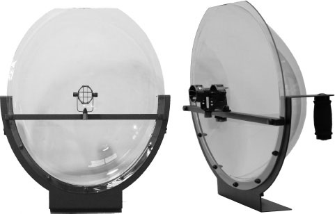
FIGURE 4.19 This parabolic microphone has a mount that allows the operator to switch out microphones depending on the recording situation. The dish is approximately 24 inches wide and the entire assembly can be mounted onto a tripod. (Image courtesy of Jony Jib Camera Solutions, Inc., www.jonyjib.com; copyright 2012.)

FIGURE 4.20 Microphone windscreens help reduce plosive sounds. (Image courtesy of Shure Incorporated.)
Another microphone accessory, the shock mount, is often used to isolate the microphone from any physical vibrations (or shocks) that may be transmitted through its stand. The microphone is suspended, usually by an arrangement of elastic bands, and isolated from the stand or boom to which it is attached (see Figure 4.22). If the microphone stand is accidentally bumped, the sound from the bump will not be passed on and amplified by the microphone.

FIGURE 4.21 A pop filter is a porous, film-like material suspended within a circular frame that is positioned in front of the microphone. (Image courtesy of Shure Incorporated. Used by permission.)
Various microphone stands or booms are used to position the microphone for different recording situations. Some stands consist of two chrome-plated pipes, one of which fits inside the other. A rotating clutch at one end of the larger diameter pipe allows the smaller pipe to be adjusted to any height desired. At the other end of the larger pipe is a heavy metal base (usually circular) that supports all of the pipes in a vertical position. Other microphone stands utilize a single pipe that’s at a fixed height. In either case, the microphone is attached to the top of the pipe by a standard thread and microphone-stand adapter (see Figure 4.23A). Floor stands adjust for the announcer in a standing position, and desk stands are used for the seated announcer. A boom stand is a long horizontal pipe that attaches to a large floor stand (see Figure 4.23B). One end of the boom is fitted with the standard thread for the microphone, and the other end is weighted to balance the microphone. The horizontal pipe allows the boom stand to be away from the announcer while positioning the microphone in a workable relationship to him or her. The boom stand is frequently found in the TV studio when the microphone must be out of the picture. A boom arm (see Figure 4.23C) is a microphone stand especially designed for use in the radio studio. It consists of metal rods and springs designed somewhat like a human arm. The microphone attaches to one end, and the other end goes into a mounting base. The whole unit can then be attached to a countertop or other production studio furniture so that the microphone can be placed in close proximity to the audio console.
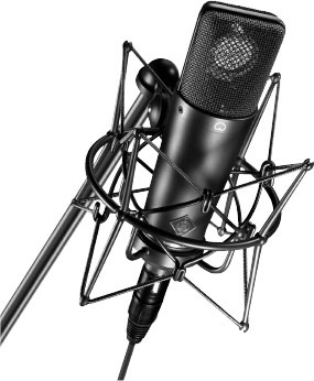
FIGURE 4.22 The microphone shock mount isolates the microphone from the microphone stand. (Image courtesy of Neumann USA.)
An understanding of microphone types, their pickup patterns, their accessories, and other characteristics is useful only if you can apply this knowledge to everyday audio production use. It seems reasonable to assume that the microphone in a studio will be a dynamic microphone, because that’s the one most commonly used in broadcasting, but keep in mind it could also be a condenser microphone. Perhaps the more important consideration is its pickup pattern. In the studio, we mainly want to pick up voices and some studio ambience. A cardioid pickup pattern, with its pickup of front and side sounds, works best to accomplish this while not picking up unwanted sounds from the rear or from the side.
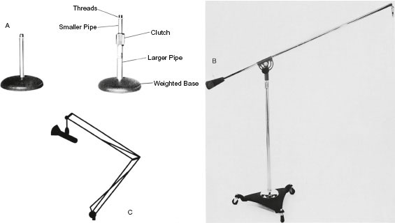
FIGURE 4.23 Microphone stands: (A) desk stand; (B) boom stand; (C) boom arm. (Images courtesy of Atlas Sound.)
Studio interviews may require you to mic a group of people seated around a table. You could use a single omnidirectional microphone in the center of the table, or you could use a separate cardioid microphone for each individual at the table. Another option is to use the PZM.
Coverage of sporting events may require the use of microphones with several different pickup patterns. Announcers could use cardioid microphones while omnidirectional microphones would be used to pick up crowd noise. Super- or hyper-cardioid microphones or parabolic microphones could be used to pick up activity on the field or court. Sometimes the venue and its settings will determine what microphones should be used; proper microphone techniques will differ, for instance, between a basketball game played indoors and a football game played outside in the snow.
PRODUCTION TIP 4A
Microphone-to-Mouth Relationship and Setting Levels
You see it online or at a live concert all the time: your favorite singers practically eating the microphone as they perform their latest hits. Don’t emulate this! “Swallowing the microphone” is not good microphone technique. When using a microphone in the studio, keep in mind two basic rules concerning distance from the microphone and position of the microphone. First, your mouth should be no closer than about 6 inches from the microphone. That’s about the length of the “hang loose” hand sign, and a good way to remember mic-to-mouth distance. You may find, however, that you need to be closer to, or farther away from the mic because of the strength of your voice or the vocal effect that you’re trying to achieve. Remembering to “hang loose” is a good starting point for using a microphone.
Second, position the microphone so that you are not talking directly into it. The mic should be positioned level with your nose and tilted down toward your mouth. Be sure to talk beneath the front of the microphone, or place the microphone below your mouth with the front of it tilted up toward your mouth, allowing you to talk across the top of it.
As if that were not enough, beginning announcers often misuse a microphone by blowing into it to see if it’s live or to set a level. This is the worst way to test a microphone and can actually damage it. In fact, the higher the quality of the microphone, the more likely that it will be damaged in this manner. The best way to set a microphone level is to read several lines of your script or ad lib some material. If you just count (“Testing… 1… 2… 3…”) or simply say “check” over and over, you’re not getting enough variation in sound to set an accurate level. Most people don’t count or say a single word over and over again in quite the same tone and volume as when they speak several sentences.
Remember, there is no one universal, standard microphone to use in every audio production. When using microphones, don’t be afraid to experiment. The bottom line for any production should be how good it sounds. It’s good to be flexible in audio production work, because sometimes you won’t have a wide variety of microphones available. But if you do have a full complement of microphones in your audio production facility, don’t be afraid to try different ones. If you use what you’ve learned in this chapter, you should be able to obtain clear, appropriate sound under a variety of circumstances.
1. What is another name for the dynamic microphone?
a) condenser
b) pressure
c) capacitor
d) PZM
2. The dynamic microphone’s sound-generating element is constructed of a diaphragm, a permanent magnet, and a voice coil. Into which of these is a small electrical current induced during use?
a) diaphragm
b) magnet
c) coil
d) none of the above
3. In what way does the condenser microphone differ from the dynamic microphone?
a) The condenser microphone needs a power supply, and the dynamic microphone doesn’t.
b) The dynamic microphone has a diaphragm, and the condenser microphone doesn’t.
c) The dynamic microphone has better sound quality than the condenser microphone.
d) The condenser microphone is bidirectional, and the dynamic microphone is omnidirectional.
4. True 5.1 surround sound is accomplished by adding what to the basic stereo setup of left and right front channels?
a) a single rear or surround channel
b) both left and right rear or surround channels
c) both left and right rear or surround channels plus a center front channel
d) both left and right rear or surround channels plus a center front channel plus a bass channel
5. Which microphone pickup pattern picks up sound on all sides?
a) hyper-cardioid
b) cardioid
c) omnidirectional
d) bidirectional
6. Which microphone would probably be most appropriate for conducting an interview on the sidelines at a football game?
a) unidirectional
b) omnidirectional
c) bidirectional
d) parabolic
7. Which microphone would probably be most appropriate for picking up a sportscaster announcing at a baseball game?
a) cardioid
b) nondirectional
c) bidirectional
d) omnidirectional
8. A microphone is a transducer, which means it can pick up sound equally well in all directions.
a) True
b) False
9. Which of the following is most likely to exaggerate the bass sounds of a person’s voice?
a) feedback
b) proximity effect
c) multiple-microphone interference
d) bass roll-off
10. What is the purpose of a shock mount?
a) to reduce plosive sounds
b) to keep the announcer’s head at least 12 inches away from the microphone
c) to isolate the microphone from mechanical vibrations
d) to prevent static electricity discharges
11. Which type of microphone stand can be farthest away from a person and still allow the person to be close to the microphone?
a) boom stand
b) floor stand
c) desk stand
d) shock mount
12. Which stereo miking technique uses two microphones crossed (like swords) at a 90-degree angle to each other?
a) split-pair miking
b) mid-side miking
c) M-S miking
d) X-Y miking
13. Which type of microphone uses small, multiple sound-generating elements within a single microphone housing?
a) ribbon mic
b) wireless mic
c) stereo mic
d) boundary mic
14. A microphone’s pickup pattern is exactly the same thing as a microphone’s polar response pattern.
a) true
b) false
15. A pop filter attaches directly to the head of a microphone.
a) True
b) False
16. Which microphone would be best at picking up sound when the sound source is a considerable distance from the microphone?
a) lavaliere microphone
b) PZM
c) RF microphone
d) parabolic microphone
17. Sound picked up from the rear of a microphone is 90 degrees off-axis.
a) true
b) false
18. When testing a microphone’s level, what should you do?
a) Say the word “testing” over and over again.
b) Read the first several lines of your copy.
c) Count from 1 to 50.
d) Blow into the microphone as hard as you can.
19. Microphone impedance refers to a microphone’s ability to create an output signal.
a) true
b) false
20. Which term describes a “screech” that occurs when sound is picked up by a microphone, amplified, fed back through a speaker, and picked up again, over and over?
a) proximity effect
b) multiple-microphone interference
c) feedback
d) bass roll-off
21. Which of the following is not a way that microphones are commonly classified?
a) a microphone’s sound-generating element
b) a microphone’s size
c) a microphone’s pickup pattern
d) a microphone’s impedance
22. Which stereo miking technique splits a pair of omnidirectional or cardioid microphones to the left and right of center about 3 to 10 feet apart?
a) Left/Right miking
b) M-S miking
c) X-Y miking
d) A-B miking
23. Which microphone has a wire spiral embedded in a circular diaphragm as part of its sound-generating element?
a) dynamic microphone
b) ribbon microphone
c) moving coil microphone
d) regulated phase microphone
24. Multiple-microphone interference can be avoided if the microphones employed are at least three times as far from each other as they are from the sound source.
a) true
b) false
25. Which of the following is not another term for a wireless microphone?
a) FM microphone
b) RF microphone
c) radio microphone
d) PZM
If you answered A to any of the questions:
1a. No. This is a different type of microphone. (Reread 4.3 and 4.4.)
2a. Wrong. The diaphragm feels the pressure. (Reread 4.3.)
3a. Right. The condenser microphone power supply is needed to charge the backplate and diaphragm.
4a. No. This would not provide surround sound. (Reread 4.16.)
5a. No. Hyper-cardioid microphones pick up sound mainly from the front. (Reread 4.7.)
6a. Wrong. Although a cardioid microphone can be used in the field, it picks up sound from mainly one direction, so it might not pick up enough of the crowd ambience. (Reread 4.7.)
7a. Yes. It would pick up the sportscaster without much of the background noise.
8a. No. Transduction has nothing to do with a microphone’s pickup pattern (Reread 4.1)
9a. No. Feedback is a howling noise caused by having open microphones near speakers. (Reread 4.11 to 4.12.)
10a. No. A pop filter or windscreen is used to reduce plosive sounds. (Reread 4.18.)
11a. Right. This is the best selection.
12a. No. This is a different stereo miking technique. (Reread 4.15.)
13a. No. As the name implies, a ribbon microphone employs a thin metallic ribbon as part of a single sound-generating element. (Reread 4.17.)
14a. Wrong. A pickup pattern is the three-dimensional shape of the area around the microphone in which it hears the sound best; a polar response pattern is the two-dimensional representation of this. (Reread 4.8.)
15a. No. (Reread 4.18.)
16a. Wrong. Lavaliere microphones are designed to be attached to the announcer’s clothing. (Reread 4.17.)
17a. No. Sound that is 90 degrees off-axis would be coming from the side of a microphone. (Reread 4.5.)
18a. Wrong. Doing this will not give a true indication of the variations of your speech (Reread Production Tip Box A)
19a. No. Impedance is an electrical characteristic similar to resistance. (Reread 4.9 and 4.10.)
20a. No. Proximity effect is a characteristic of microphones that accents the bass response. (Reread 4.11 to 4.12.)
21a. No. Microphones are categorized by their sound-generating elements. (Reread 4.2, 4.3, and 4.4.)
22a. No. There is no such term. (Reread 4.15.)
23a. Wrong. Dynamic microphones do have a wire coil as part of their sound-generating element, but it’s not configured like this. (Reread 4.3 and 4.17.)
24a. Yes. This is a true statement.
25a. No. FM microphone is another term for a wireless microphone. (Reread 4.17.)
If you answered B to any of the questions:
1b. Correct. The dynamic microphone is also called a pressure or moving-coil microphone.
2b. Wrong. The magnet sets up the field. (Reread 4.3.)
3b. No. Both microphones have a diaphragm. (Reread 4.3 and 4.4.)
4b. No. This would not provide surround sound. (Reread 4.16.)
5b. Wrong. The cardioid picks up sound on all but one side—usually the one right behind the microphone. (Reread 4.7.)
6b. Correct. An omnidirectional microphone would pick up from all sides, thus easily miking both the interview and some crowd noise.
7b. No. The crowd noise would tend to drown out the announcer. (Reread 4.7.)
8b. Yes, this is the correct answer.
9b. Right. When an announcer gets too close to the microphone, the bass may be exaggerated.
10b. No. For one thing, the announcer’s head should be about 6 inches away, not 12 inches away. (Reread 4.18 and Production Tip 4A.)
11b. No. A person must stand right beside a floor stand. (Reread 4.18.)
12b. No. This is a different stereo miking technique. (Reread 4.15.)
13b. No. Wireless microphones employ a transmitter (often part of the microphone) and a receiver, but this is not a description of this system. (Reread 4.17.)
14b. Right. This is the correct response.
15b. Correct. Pop filters are not attached directly to a microphone.
16b. Wrong. PZMs are designed to be placed on a flat surface, such as a tabletop. (Reread 4.17.)
17b. Yes. This statement is false. Sound that is picked up from the rear of a microphone is 180 degrees off-axis.
18b. Correct. Doing this allows you to get the most accurate levels in regard to variations in your voice and reading style.
19b. Correct. Microphone sensitivity refers to a microphone’s ability to create an output level.
20b. No. This is not correct. Multiple-microphone interference is a phase problem that creates peaks and cancellations in the sound. (Reread 4.11, 4.12, and 4.13.)
21b. Correct. Although microphones come in a wide variety of sizes, they are not usually categorized by size.
22b. Wrong. This technique requires the microphones to be close together. (Reread 4.15.)
23b. No. The ribbon microphone uses a thin ribbon suspended between two magnets for its sound-generating element. (Reread 4.17.)
24b. No. The statement is true. (Reread 4.13.)
25b. No. RF microphone is another term for a wireless microphone. (Reread 4.17.)
If you answered C to any of the questions:
1c. No. This is another name for the condenser microphone. (Reread 4.3 and 4.4.)
2c. Correct. The current is in the coil.
3c. No. The condenser microphone usually has slightly better sound quality than the dynamic microphone. (Reread 4.3 and 4.4.)
4c. No. This wouldn’t provide true surround sound although you’re getting close. (Reread 4.16.)
5c. Yes. An omnidirectional microphone picks up on all sides.
6c. No. Although this microphone could pick up the interview nicely, it wouldn’t get much crowd noise. (Reread 4.7.)
7c. No. A bidirectional microphone picks up on two sides, and the sportscaster would be on only one side. (Reread 4.7.)
9c. No. This will create a distorted signal. (Reread 4.11 and 4.13.)
10c. Yes. This is a special type of microphone holder that suspends the microphone.
11c. No. A desk stand has to be right in front of the person. (Reread 4.18.)
12c. No. This is a different stereo miking technique. (Reread 4.15.)
13c. Yes. This is the correct answer.
16c. No. RF microphones are wireless, but they don’t have exceptional distance pickup characteristics. (Reread 4.17.)
18c. Incorrect. All this will do is make the person taking your levels angry. (Reread Production Tip Box A.)
20c. Correct. That screeching, howling sound is feedback.
21c. No. Microphone pickup patterns are used to categorize microphones. (Reread 4.2 and 4.5.)
22c. Wrong. This miking technique requires crossed microphones at an angle that can vary from 90 to 140 degrees. (Reread 4.15.)
23c. No. The moving coil microphone is just another name for the dynamic microphone. (Reread 4.3 and 4.17.)
25c. No. Radio microphone is another term for a wireless microphone. (Reread 4.17.)
If you answered D to any of the questions:
1d. No. A PZM does not indicate a type of construction. (Reread 4.3 and 4.17.)
2d. Wrong. (Reread 4.3.)
3d. No. Both dynamic and condenser microphones can have omnidirectional or bidirectional pickup patterns. (Reread 4.3, 4.4, 4.5, 4.6, and 4.7.)
4d. Yes. These components when added to the stereo left and right front channels make up 5.1 surround sound.
5d. No. A bidirectional microphone picks up sound from the front and back of the microphone. (Reread 4.7.)
6d. No. This microphone is better for picking up crowd or field noise and not for interviews (Reread 4.17.)
7d. No. This is another term for nondirectional. (Reread 4.7.)
9d. Wrong. Bass roll-off is an electronic “turn down” of bass frequencies. (Reread 4.11.)
10d. No. This is not the correct answer. (Reread 4.18.)
11d. No. Although this is often used in conjunction with a microphone stand, it won’t determine the distance between announcer and microphone stand. (Reread 4.18.)
12d. Correct. This is a description of X-Y stereo miking technique.
13d. No. Boundary microphones employ a single sound-generating element in conjunction with a sound-reflecting plate. (Reread 4.17.)
16d. Right. Parabolic microphones will pick up sound from a point some distance away.
18d. Wrong. In addition to not even getting a level for your voice, all you will do is get spit on the microphone and possibly damage it. (Reread Production Tip Box 4A.)
20d. No. Bass roll-off is a switch on some microphones that electronically turns down the lower frequencies. (Reread 4.11 and 4.12.)
21d. No. Microphone impedance is used to categorize microphones. (Reread 4.2 and 4.9.)
22d. Correct. This describes the A-B miking or spaced pair technique.
23d. Yes. This is the correct response.
25d. Yes. The PZM is a type of boundary microphone that is designed to be placed on a flat surface, such as a tabletop.
Position microphones in various ways to create different effects.
Purpose
To enable you to experience proximity effect, feedback, multiple-microphone interference, and the differences in sound quality that occur when a microphone is placed at different distances and angles from an announcer.
Notes
1. You may need some help from your instructor or the engineer in setting up the equipment.
2. For the proximity effect, try to find a microphone that doesn’t have a bass roll-off switch, or make sure it’s switched off if it does.
3. Don’t allow feedback to occur for too long. It can be damaging to all the electronic equipment—and your ears. You may have to plug the microphone into something other than the audio board if the board automatically shuts off the speakers when the microphone is turned on.
4. For multiple-microphone interference, make sure that the microphones are closer than 3 feet apart. Omnidirectional microphones will demonstrate the effect the best.
5. Use a cardioid microphone for the distance and angle experiments, because it will demonstrate the points better.
How to Do the Project
1. Set up an audio board so that two microphones are fed into it and so that the sound of those two microphones can be recorded on an audio recorder.
2. Put the recorder in record mode and activate one of the microphones. Start talking about 2 feet away from the microphone, and keep talking as you move closer until you are about 2 inches from it. As you talk, say how close you are to the microphone, and mention that you’re experimenting with the proximity effect. Stop or pause the recorder.
3. Position a microphone so that it’s close to an activated speaker. Turn on the audio recorder and talk into the microphone. Record a short amount of the feedback and turn off or pause the recorder.
4. Position two microphones in front of you that are less than 3 feet apart. Put the audio recorder in record mode and talk into the microphones, saying that you’re testing for multiple-microphone interference. Turn off or pause the recorder.
5. Position one microphone in front of you. Put the audio recorder in record mode. Position yourself 12 inches from the microphone and talk into it. Then position yourself 6 inches from the microphone and talk directly into it. Then talk across the top of the microphone. Move 6 inches to the side of the microphone, and talk into it with your mouth positioned to speak across the top of it. Get behind the microphone, either by moving behind it or by turning it around, and talk from about 6 inches away. Describe each action as you do it.
6. Listen to the recording to hear the various effects and to see that you have, indeed, recorded all the assignments. If some of them didn’t turn out as well as you would have liked, redo them.
7. Write a brief observation of each effect explaining what you hear on your recording.
8. Turn in your recording and your observations to your instructor to receive credit for this project. Make sure you put your name on it and label it “Microphone Placement.”
With several other students, make a recording using stereo miking techniques.
Purpose
To give you experience using standard microphones to employ various stereo miking techniques.
Notes
1. Which technique you employ will depend on the microphones that are available at your facility.
2. Because this project requires several people, your instructor may assign it as a group project.
3. The “How To” section that follows uses X-Y techniques for illustration purposes; you can adjust it for any of the other techniques.
How to Do the Project
1. At one end of your studio (or room) arrange at least three students in a left–center–right configuration. This could also be three groups of students or even a small musical group, as long as they’re arranged so that specific sections can be identified as left, center, or right.
2. Set up two cardioid microphones to record onto an audio recorder.
3. Arrange the microphones in an X-Y position as described in the text, in line with the “center” of the students or group.
4. Begin recording and have the students or group do the following:
a have the left say something
b have the right say something
c have the center say something
d have all three sections say something different, but at the same time
e have just the center say something
f have the left and right say something
g have all three sections say something
5. As you are recording the variations in Step 4, make sure to identify each segment by having one student say something like, “This is just the ‘left’ group,” before the group says anything.
6. Play back your recording. Are you able to “hear” the stereo image correctly? Does the left group “appear” to be located left? Make some observations about the recording results and write them down.
7. Repeat the same recording, but use a single microphone; that is, record in mono.
8. Listen to the second recording. What differences do you hear between the two recordings? Write down your observations again.
9. Turn in your recording and the observation sheet labeled with your name and “Stereo Miking” to your instructor to receive credit for this project.
Compare sound from different types of microphones.
Purpose
To learn the differences between dynamic and condenser microphones and between cardioid and omnidirectional pickup patterns.
Notes
1. You may need help from your instructor or engineer in setting up the equipment.
2. Don’t be concerned if you can’t discern differences between the dynamic and condenser microphones. The pop and hiss effect doesn’t occur for all voices.
3. If your facility has microphones with other sound-generating elements (such as ribbon or regulated phase) or other pickup patterns (such as bidirectional or ultra-cardioid), add those to the exercise.
How to Do the Project
1. Select a dynamic and a condenser microphone from those at your facility.
2. Attach the microphones to an audio recorder. You can put both microphones through an audio console and use them one at a time, or you can attach each microphone to the recorder in its turn.
3. While you’re recording, say the following into the dynamic microphone: “Peter Piper picked a peck of pickled peppers,” and “She sells seashells by the seashore.” Turn off or pause the recorder.
4. Repeat Step 3, but use the condenser microphone.
5. Select a microphone with a cardioid pickup pattern and another microphone with an omnidirectional pickup pattern from those at your facility.
6. Attach the microphones to an audio recorder as in Step 2.
7. Position the cardioid microphone on a stand and, while recording, walk all the way around the microphone, saying where you are as you move: for example, “Now I’m right in front of the microphone; now I’m 90 degrees to the right of the front of the microphone.” Turn off or pause the recorder.
8. Repeat Step 7, using the omnidirectional microphone.
9. Listen to the recording, and write down any observations you have about the differences among the various microphones.
10. Turn in the paper and your recording to your instructor to receive credit for this project. Be sure to include your name on both and call the assignment “Microphone Comparisons.”
Diagram/Apply miking techniques to various on-campus or local sporting events
Purpose
To see how a variety of sporting events and conditions can affect microphone selection and placement.
Notes
1. You may want to consult your instructor, chief engineer, or team coach(es) about which microphones to use and where they could be placed in your campus stadiums.
2. You may want to consider and address how many production assistants you would need to properly mic the field or stadium.
How to do the project
1. Draw diagrams of the playing fields, courts, and rinks at your school:
• Football
• Baseball
• Basketball
• Tennis
• Soccer
2. Consider the conditions of each location. Where are the crowd bleachers located? Where is the press box located? Are there any “special effects” or traditions you should be aware of (i.e., cannons being fired after each home touchdown)?
3. Consider the possible weather conditions, especially if the game is played outdoors. Consider the acoustics of sports played indoors. Use these considerations to determine not only where you will place your microphones, but also what microphones you will use.
4. Fill out your diagrams with microphones clearly located where you would place them. If your school does not have a competitive team for a sport listed above, create a diagram that would show how you would mic the field for intramurals instead. In addition to turning in a diagram for each sport listed above, turn in a typed/printed report that lists the types of microphones you would use, where you would place them, and why. Turn in the diagrams and your paper to your instructor to receive credit for this project. Be sure your name is on both the diagrams and your report.