
Woven Electronic Textiles
Tomohiro Kuroda1, Hideya Takahashi2 and Atsuji Masuda3, 1Kyoto University Hospital, Kyoto, Japan, 2Osaka City University, Osaka, Japan, 3Industrial Technology Center of Fukui Prefecture, Fukui, Japan
Establishing an industrial production process for manufacturing of complex e-textiles is indispensable for making wearable sensors commodity goods. This chapter introduces weaving, the most common approach to developing textiles. Weaving enables both prototyping and mass production with the same production process, and is available to embed complex circuits or specially designed device-carrying yarn into multi-layered textiles. This chapter introduces basic techniques of weaving suitable for e-textile production, materials such as conductive yarn and device-carrying yarn, and advanced techniques such as jacquard or dobby loom for implementation of complex circuits or multi-layered textiles. This chapter also provides examples of several typical applications of woven e-textiles.
Keywords
Weaving; e-textile; yarn; loom; complicated circuit; electronic device
1 Introduction
Wearable sensors are designed to be unobtrusively and seamlessly worn in everyday life. Therefore, most of the wearable sensors should be embedded into clothing. Although some of the wearable sensor designs rely on mounting electronic components on ready-made clothes using existing or added pockets and compartments, a better approach is to develop clothing based on fabrics with embedded electronics. The fabrics with embedded electronics are called e-textiles, electronic textiles or smart textiles [1]. Establishing an industrial production process to manufacture e-textiles is needed to make wearable sensors a commodity. This production process must be available for complex textiles since e-textiles are much more complex than conventional fabrics. Additionally, the production process should be available for both prototyping and mass production, just as with modern microchip production processes.
A common academic approach to develop e-textiles is embroidery. Embroidery is a handy method for prototyping simple e-textiles, as it requires just a single sewing machine. On the other hand, embroidery has clear drawbacks for mass production of complex e-textiles, because embroidery cannot be used for implementation of multi-layer circuits and the production speed is quite limited. Another often utilized approach is knitting [2]. However, knitted products are bulkier than woven products, which have more flow and can be made much thinner.
Weaving has been the most common approach to producing fabrics throughout history. Mass production of textile fabrics with graphical patterns of certain complexity was established as an industrial process in the eighteenth century when Joseph Jacquard (Figure 1) invented an automated loom controlled by punched cards. The Industrial Revolution, derived from Jacquard’s invention, introduced the concept of “programming” by punched card, which also counted as an information revolution [3]. The long history of industrial development after Jacquard’s invention has enabled the textile industry to produce complex-structured fabrics, such as multi-layered fabrics.

The key to implementation of machine-woven electronic textiles is using an appropriate conductive, or functional yarn available for weaving machine, and in establishing a weaving process for such non-standard yarn. This chapter provides several snapshots of frontier research on yarn production and development of the production process as well as basics of the textile industry. This chapter also provides several example prototypes of e-textiles created by weaving.
2 Textiles
Fabric, a flat fibrous structure, can be classified into three groups, non-woven cloth, knitted fabric, and textiles, according to its structure and production process.
A textile is composed by orthogonally crossing yarns, called warp and weft. Despite its rather simple structure, the variety, density, and crossing patterns of yarns derives textures with various natures. Textile made by hygroscopic fibers with open weave is good for summer clothing, whereas a textile with stiff structure of thin and strong fibers is preferable for tents. Thus, to produce a textile with certain nature, we need to find the best combination of structure and materials.
The following sections provide an overview of basic technologies of yarns and textile weave meant for e-textiles.
2.1 Yarn
Yarn is a long continuous length of interlocked fibers. Conventional yarns used for textiles are made of natural fibers such as silk, cotton, wool, and synthetic fibers such as polyester and polyamide. Special purpose textiles designed for industrial applications utilize specially designed fibers such as carbon fiber or aramid fiber. E-textile requires both conventional yarn and special yarn with conductive fibers or with fiber-mounted electronic devices. For example, carbon nanotube-plated yarn [4] and metalized aramid fiber [5] may be used in a textile heater.
Among various ways to produce conductive yarn, conductive yarn suitable for e-textile can be produced from two types of fibers, filamentous conductive metal (metal fiber) and conventional fiber plated with conductive metal. As the nature of metal fiber, such as its elasticity, is different from conventional fiber, various yarn-production techniques are applied to make the yarn applicable for machine weaving. For example, Figure 2 shows a conductive yarn produced by entwining metal fiber around conventional yarn, and Figure 3 shows a yarn composed of metal fiber braids. On the other hand, metal-plated yarn is easily applicable for machine weaving, as its nature is similar to conventional yarn. However, sometimes the metal plating comes off during the textile production process, and the metal-plated yarns lose conductivity. Several metal-plated yarns are available commercially [6]. Metal-based conductive yarn with low resistance is preferable to carry electric signals. On the other hand, carbon-based fibers, whose resistance is relatively high, can be applicable for heating.


Recently, electronic devices such as IC (integrated circuit) chips or LEDs (light emitting diode) were mounted onto or embedded into fibers. Figures 4 and 5 show monofilament fiber of 1.5 mm embedding RFID (radio frequency identification) chips. This fiber is slightly thicker than ordinal yarn because of a resin layer covering the fiber. However, the nature of the fiber is similar to ordinal polyester, which is waterproof and available for machine weaving. With a high-strength fiber such as aramid as the core, the resulting RFID fiber becomes high strength as well [7]. The authors developed RFID fibers operating in different frequency bands, such as 2.45 GHz SHF RFID and 860 MHz to 960 MHz UHF-band RFID. The electronic textiles with embedded RFID fibers can be used for uniform management, counterfeit prevention, and even cotton management during the surgical operation (Figure 6).


2.2 Textile Weaves
A textile is composed of orthogonally crossing yarns, called warp and weft. The crossing pattern is called the textile weave and the minimal repeating pattern is called the weave repeat. The most basic of the three fundamental types of textile weave, plain weave, is composed so that the warp and weft are aligned to form a simple criss-cross pattern. Each weft goes over a warp, then under the next one. The pattern alternates as shown in Figure 7. As the weave repeat of plain weave is simply a crossing pattern of warp and weft, innumerable patterns are available.

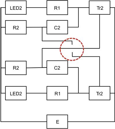
Production of multi-layered structures in woven textiles is also an easy task and can be created by piling up warp or weft or both of them. Simple weave repeat enables us to pile up many threads. Figure 8 shows an example of weave repeat of two-layered textile, and Figure 9 shows the cross-section of five-layered textile. By introducing conductive yarn into multi-layered textile, we can embed a topologically complicated circuit with unconnected trace crossings within a textile. Figure 10 shows a simple LED switching circuit, with equivalent woven pattern suitable for multi-layered textile shown in Figure 11. As marked by the circle in the middle of the image, this circuit has intersecting but unconnected traces that cannot be implemented in a one-layered textile. Figure 12 shows the resulting prototype. In the prototype, intersecting but isolated traces are implemented by placing two conductive yarns in skew position within a two-layered textile. The layered structure makes the circuit durable to the deformations caused by body motion or washing [8].


2.3 Looms
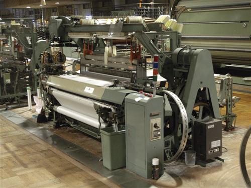
A loom (Figure 13) is a textile-production machine. The loom controls two required motions: shedding motion to open warp (Figure 14), and insertion motion to insert weft between the raised and lowered warps (Figure 15). Looms can be classified by the variety of the two motions.


Common shedding motions enable most complicated textile weaves such as dobby and Jacquard. Common textiles 1 m wide use thousands of warps. The dobby loom handles warps in groups, whereas the Jacquard loom controls each warp.
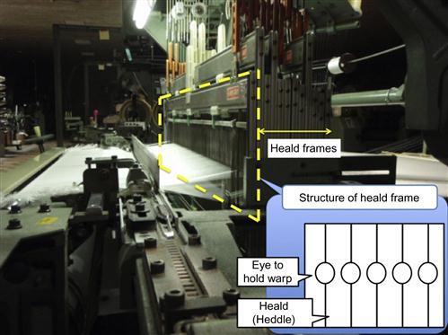
The common dobby loom has 12 to 30 heald frames (Figure 16). Each heald frame handles one group of warps. For example, a dobby loom with ten heald frames handling 1,000 warps produces textile of 10,000 warp ends wide with ten repeats of the weave going across. As the dobby loom can manage heald frame so flexibly, the dobby loom can produce complicated textile weaves.
The Jacquard loom (Figure 17) can handle each warp individually. This mechanism enables the Jacquard loom to produce large designs or complicated patterns the dobby loom cannot. Figure 18 shows an example of a large pattern produced by a Jacquard loom. Similar to the dobby loom, the number of independently controlled heddles (heddle set) defines the pattern complexity of the Jacquard loom. The number of heddles of commercially available Jacquard looms varies from hundreds to thousands. To weave a 5,000 warp ends-wide textile, a Jacquard loom with 5,000 heddle sets can handle all warps independently, and a Jacquard loom with 1,000 heddle sets repeats the same weave five times. Figure 18 shows an example of an 8,000 warp ends-wide textile using a Jacquard loom with 4,000 heddle sets. So the same pattern repeats twice along weft.


Common insertion motions available for various wefts are shuttle and rapier.
A shuttle loom inserts the weft into a boat-shaped case called the shuttle (Figure 19) and throws the shuttle between raised and lowered warp threads as shown in Figure 14. As the shuttle loom inserts the weft thread with a spool, the loom inserts the weft without cutting it. Therefore, the shuttle loom enables embedding of complicated circuits created from a conductive yarn weft. On the other hand, as the weft must be reeled up into the shuttle beforehand, productivity of the shuttle loom is low.

A rapier loom inserts weft using a long tape or a pole with a thread-holding mechanism, called a rapier, on its end (Figure 20). The rapier hooks and pulls the weft from one end to the other. Thus, the look and motion of the rapier is similar to a double-edged sword, just as its name suggests. Unlike a shuttle loom, the weft in the rapier loom must be cut on each insertion. On the other hand, the direct-hooking mechanism of the rapier loom allows for handling of thick yarns, fancy yarns (yarns with uneven thickness or loops), or elastic yarns. Therefore, due to its flexibility, a rapier loom is used for expensive textiles or complicated industrial materials.

3 Applications
This chapter covers four typical e-textile applications.
Section 3.1 introduces an application of a simple textile with conductive yarn. Section 3.2 introduces an application of a simple structured multi-layer textile with both conductive and non-conductive yarn, and section 3.3 presents an example of a complicated circuit woven by Jacquard and shuttle. Finally, section 3.4 introduces an example of a textile with device-embedded yarn.
3.1 Touchpad
This section introduces a fabric touchpad [9] that can be mounted on clothing (Figure 21) as an input interface for wearable computers. The touchpad is implemented by a simple weave with a conductive yarn.

Figure 22 shows the composition of the touchpad. The touchpad is composed of a square-shaped textile made of conductive yarns (conductive textile) and electrodes attached to the four edges of the textile. Same voltage e is applied to each electrode through signal pickup resistors. The conductive textile can be regarded as an equivalent to a resistor array as shown in Figure 23. Once the user touches the conductive textile with his/her fingertip, a capacitor is created between the fingertip and the textile and weak electric current is sent through the human body and the capacitor. The electric current through each of the pickup resistors varies due to the position of the fingertip. Therefore, the position of the fingertip can be pinpointed from the voltages measured at the pickup resistors R1 and R2.


Figure 24 shows the measurement mechanism of the finger position along the x-axis. When the size of the touchpad is ![]() , the position of the fingertip is
, the position of the fingertip is ![]() , the resistances are
, the resistances are ![]() , the impedance of the human body is
, the impedance of the human body is ![]() , and the resistance between the fingertip and the resistor on the left end of the touchpad is
, and the resistance between the fingertip and the resistor on the left end of the touchpad is ![]() . The voltages
. The voltages ![]() on the resistance
on the resistance ![]() and
and ![]() on the resistance
on the resistance ![]() are defined as follows:
are defined as follows:
(1)
(2)
Thus, the position of fingertip along the x-axis, ![]() , is given as
, is given as
(3)

The position of the fingertip along the y-axis, y, is given in the same manner as
(4)
(5)
(6)
Figure 25 shows the prototype. The prototype is a patch of 12 cm×10 cm conductive textile with four electrodes.

This prototype provides functionality typically available in a standard single-touch touchpad, such as pointing, selecting, clicking, and dragging. Figure 26(b) and (c) shows the measured voltage while the fingertip moves along the x-axis and y-axis defined as Figure 26 (a). The results in Figure 26 indicate that the measured voltage accurately pinpoints the position of the fingertip on the pad.

Because the prototype touchpad is composed of a plain-weave textile and resistors, the deformation of the textile does not harm its measurement performance, and the sensor is easy to wash and to mount on any clothes.
3.2 Textile Switch
This section introduces a textile switch [10] implemented through use of a multi-layered fabric with a simple structure. Figure 27 shows a sketch of a cross-section of the textile switch. Mounting multiple conductive yarns into multi-layered textile allows alignment of the yarns into a skewed position. The conductive yarns contact each other when the textile is pressed to crush the gap between the layers.

The pressure required for the switching operation can be controlled by the materials of the yarns or the structure of the textile. The characteristic response time of the prototype textile switch is only 100 μs, which allows for switching action up to 30 Hz [11]. A cyclic pressure test, applying a pressure of 20 kPa at a frequency of 20 Hz reveals that the durability of the prototype is more than 1 million switching cycles.
The prototype is thin and flexible, and can be mounted anywhere; for example as a room entrance counter that can detect direction of passing people by utilizing a multi-section textile sensor [12].
3.3 Textile Electrodes
This section provides an example of an e-textile with a complicated weave pattern. A Jacquard loom with shuttle enables the creation of complicated circuit patterns from a single continuous conductive yarn as discussed in section 2. Japanese traditional weaving, NISHIJIN [13], is a good example of this type of weaving.
Figure 28 shows a prototype of an electrode for electrocardiogram (ECG) signal acquisition [14]. The conductive yarn is composed of three 40 μm stainless braids as shown in Figure 3. The electrode textile is woven by TSUZURE (brocade), which is a manual weaving operation with shuttles. The three circles and one dot are woven from independent conductive yarns, and each figure is woven from a continuous yarn. Thus, the electric properties of the textile are favorable for measuring weak bio-signals. If the electrode was composed of several independent conductive yarns contacting each other, then the weak bio-signals may be significantly attenuated at the connections between yarns.

Figure 29 shows another example: a twelve-lead ECG vest. The textile is produced by NUIWAKE; the machine weaving using a Jacquard loom and shuttle producing a TSUZURE-like weave. Here again, each electrode is composed of continuous conductive yarn (twisted silver-plated polyester and rayon). Figure 30 shows the obtained ECG signal.

3.4 RFID Textiles
This section introduces textiles with electronic devices embedded into the yarn. RFID is widely used as a non-contact communication device. Passive RFID tags are typically thin and tiny, powered by the electromagnetic waves emitted by the transceiver, and are widely applied in the apparel industry, such as in uniform management. The conventional method to introduce an RFID tag into clothing is to attach it as a price tag or to sew the tag into the clothing. Embedding RFID tags during textile manufacturing may be preferable. This section presents two different methods to embed RFID tags into textiles.
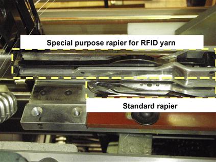
The first approach is to weave a specially developed RFID fiber as shown in Figure 5, or a tape-shaped RFID yarn as shown in Figure 31 into the textile. The authors developed RFID yarns embedding 2.45 GHz SHF band, 13.56 MHz HF band, and 860 MHz to 960 MHz UHF band RFID tags. To insert this yarn as weft, the authors also designed and developed a new rapier loom as shown in Figure 32 [15]. The developed loom has both standard rapier and special-purpose rapier to insert tape-shaped RFID yarn. The loom switches between these two rapiers repeatedly and produces RFID textiles, as shown in Figure 33, automatically and continually. The produced RFID textile can be laminated processed into tile carpet (Figure 34) through a standard cloth-manufacturing process [16].


Another approach is to directly embed RFID chips into textiles [17]. Figure 35 shows an example of an embedded washable UHF-band linen tag [18] integrated into the textile during the production process. The RFID tag is inserted into a pocket within two-layered textile using a slightly modified standard loom. Since the tag is fully integrated with the textile, it is impossible to remove the tag without cutting the textile.

RFID was originally designed for logistics and item tracking. The apparel industry primarily utilizes RFID for logistics [19], such as laundry service or uniform management. However, several other applications have been proposed.
One such application is positioning. By using a database of positions of multiple RFID tags embedded into the floor, a moving object such as a robot with an RFID reader can position itself [20].
Another possible application is in nursing, such as in urination detection for disposable diapers [21]. Figure 36 shows an RFID fiber embedded into a disposable diaper. As the RFID fiber shown in Figure 5 is just as soft as conventional yarn, unlike conventional RFID tags, the fiber won’t decrease the touch and feel of the diaper [22,23]. Figure 37 shows the mechanism to detect urination. As illustrated in the upper portion of Figure 37, the RFID fiber responds with its own ID whenever it is activated by the reader, which also works as the power source. When the diaper is wet, as illustrated in the lower sketch of Figure 37, a high-molecular absorber that is full of moisture changes the antenna property of the RFID fiber and thus prevents it from responding to the reader’s signal, causing the system to detect urination. The reader antenna can be placed under the bed pad or seat of a wheelchair.


4 Summary
This chapter presented electronic textiles mainly produced by weaving. The weaving enables textiles to embed complicated circuits as shown by the NISHIJIN electrode example or specially designed electronic yarns as shown by the RFID textile example. Thus, the weaving technique can be a silver bullet to enrich a variety of e-textiles: it may be used to implement textiles with embedded LEDs, embedded physical or chemical sensors, and even textiles with integrated electronic circuits.
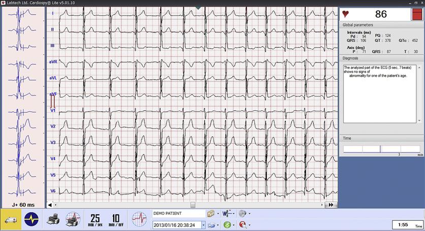
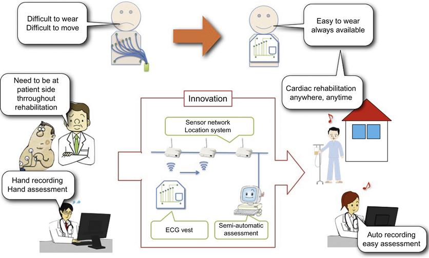
Wearable sensors made of such enriched e-textiles coupled with a ubiquitous computing environment may provide innovative ubiquitous information services. Figure 38 shows an example of such a health service. A twelve-lead wearable vest coupled with a sensor network with indoor localization capabilities [24,25] enables patients after cardiac events to perform rehabilitation under the eyes of a computational health condition assessment system, which continuously monitors vital signs and calls medical personnel in the case of an emergency.
The enriched e-textile may even change the paradigm of information services. Our daily life is full of textiles: carpets, sleeping mats, wallpaper, etc. Thus, e-textiles can be used not only for wearable sensors but also for housing materials. Once e-textiles acquire sensing, computational, or communication capabilities, they may enable our living environment to provide information services. An intelligent sleeping mat or sofa could check your health condition throughout the day to report to your doctor, and intelligent wallpaper with air pollution, temperature, and moisture sensors could initiate ventilation and air-conditioning to keep air fresh and confortable.
Overall, e-textiles will likely penetrate most of the aspects of our daily lives in the very near future, and mass production of e-textiles by weaving techniques is one of the enabling factors for their broad dissemination.
Glossary
Brocade a class of richly decorative shuttle-woven fabric. The decorative pattern is created by non-structural supplementary weft to give the appearance of an embroidered pattern.
Embroidery decorating fabric with a needle and a thread of yarn.
Fabric a material made of fibers.
Heddle A component of a loom, which holds a warp through its eye to raise and lower it.
Knitted fabric fabric consisting of a number of consecutive rows of loops.
Non-woven cloth fabric made from long fibers bonded together by chemical, mechanical, heat, or solvent treatment.
Skew position (Mathematics) Neither parallel nor intersecting placement of two straight lines within three dimensional space.
(Woven) Textile fabric consisting of two distinct sets of yarns interlaced orthogonally.
Textile heater textile able to generate heat from electric power supply.