
2
PRE-PRODUCTION/PREPARATION
CAMERA ANGLE PROJECTION
Steven D. Katz
Drawing What the Lens Sees
Reprinted from the book Film Directing Shot by Shot: Visualizing from Concept to Screen1 with the permission of the author, Steven D. Katz, and the publisher, Michael Wiese, who retain the copyright. The illustrations were redrawn for The VES Handbook through the generosity of Mr. Katz. Bill Taylor’s comments are in brackets.
[While drafting is properly the province of the art department, the demands on their personnel sometimes exceed the available time. When the visual effects team needs to know (for example) where to put their cameras, or how big the green screen needs to be to cover the action, it’s good to know how to find the answers independently if necessary. A knowledge of basic projection techniques will prove invaluable to the VFX Supervisor or VFX DP, if only to improve communication with the production designer and his or her team.]
Art director Harold Michelson devised the following method for camera angle projection; production illustrator Camille Abbott showed it to the author. Once mastered it is a useful technique for previewing set plans and camera placement.
In essence, camera angle projection is a way of using the information on a plan and elevation to plot a simple perspective drawing according to the rules of linear perspective. In linear perspective all parallel lines and edges of surfaces receding at the same angle are drawn on the picture plane in such a way that they converge toward a single vanishing point.
The angle at which parallel lines and surface edges recede determines the degree of convergence in a perspective drawing in exactly the same way that the focal length of a lens determines the degree of convergence in a photograph. Figure e2.1 shows a box as it would appear through a long focal length lens (a) and a wide-angle lens (b). Notice that the angle formed near the vanishing point on the horizon line is smaller for a long focal length lens than for a wide-angle lens.

Figure e2.1 (Drawing courtesy of Steven D. Katz.)
The lens tables in the American Cinematographer Manual list the angles of view (height and width) for prime lenses with common focal lengths. The point to remember is that the angle of view for any lens can be used to determine the degree of convergence for a perspective drawing. With this information, a perspective drawing can be made to represent what any given camera lens would see. With simple drafting techniques, it’s possible to use the dimensions on the plan and elevation of a set, along with the camera angles for a given lens and aspect ratio to make a perspective drawing. This is camera angle projection.
To make a projection drawing for any camera angle and lens, begin with a blueprint plan and elevation of a set or the dimensions of key points measured at a real location. A projection can have either a two-point or three-point perspective. When the camera is tilted up or down less than 23 to 30 degrees from the ground plane, a two-point perspective is sufficiently accurate for the projection. Relatively low- or high-angle shots, however, must be drawn in three-point perspective, which is a considerably more difficult procedure. For most visualization needs, two-point projection is adequate and that is the system illustrated here. At the time this is being written (1991) there is no text or course that teaches three-point perspective; it can be learned from industry professionals such as art directors and production illustrators.
[Note that as long as the camera is close to perpendicular to (for example) a building front, draw extremes of tilt by simply turning the drawing 90 degrees, transforming pan into tilt. It’s still a two-point perspective.]
Tools for Projection
Projection employs drafting techniques familiar to architects and a few basic drafting tools: a 90-degree triangle, a protractor, tracing paper, pushpins, a ruler (preferably an architect’s scale), a pencil, and a divider for transferring measurements. [Of course, a computer digital drafting program will work too!] The table of lens angles printed at the end of this section will be required as well.
Preparation
Before making the projection, draw the camera angle on tracing paper. There are two camera angles for any lens, one for the height of the frame and one for width, both measured in degrees.
The size of the shot determines the angle to use. The location projected in this example is a small interior, and since the desired shot sees a good portion of the room, a wide-angle lens is appropriate, in this case 25mm. This example uses the 1:85 aspect ratio shown in Figure e2.2.
Because the projection camera angles will eventually be transferred to the plan, draw the angle large enough to cover a good portion of the plan drawing.

Figure e2.2(Drawing courtesy of Steven D. Katz.)
The solid outer lines represent the width of the space the camera sees, an angle of 47 degrees. The inner dotted lines represent the height of the space, an angle of 27 degrees. [Viewing the horizontal and vertical angles together may seem confusing at first, but it greatly speeds up the location of points on the image.]
The camera is positioned at the point where the four angle lines converge. This is called the camera station point (SP). An additional line is placed down the center of the angles. This is called the center line (CL). The center line represents two things: the center line of the width of the frame and the horizon line of the height of the picture plane.
The picture plane (line BD) is perpendicular to the center line. The picture plane represents the view that is being drawn.
Because the relationship between the horizontal and vertical dimensions is the aspect ratio, the angles vary with the format. Figure e2.3 shows the relationship between the camera angles and the aspect ratio. The projection plane is the frame in which the perspective drawing will be made.

Figure e2.3 (Drawing courtesy of Steven D. Katz.)
Now add the horizon line FG to the projection frame in Figure e2.4. As with any linear perspective drawing, the horizon line represents the eye level of the viewer, which in this case is the camera. The camera lens is commonly 4 ft off the ground, which causes the real horizon to bisect a standing adult figure in a pleasing proportion. With the lens at 4 ft, the horizon line is also set at 4 ft in the picture.

Figure e2.4 (Drawing courtesy of Steven D. Katz.)

Figure e2.5 (Drawing courtesy of Steven D. Katz.)

Figure e2.6 (Drawing courtesy of Steven D. Katz.)
A vital concept to note is that any object in this picture, regardless of distance from the camera, will be 4 ft from the ground where it touches the horizon line.
Next, add a vertical line HI that vertically bisects the horizon line in the center of the frame. Thus the vertical line HI represents the center line of the width of the aspect ratio, and the horizontal line FG represents the horizon line.
Now place the plan and elevation drawing (Figure e2.5) on a thick piece of poster board. This will make it possible to put a pushpin in the camera position.
Now frame the shot using the lens angle drawn on the tracing paper: Place the tracing paper on the plan view as shown in Figure e2.6 and position the angle so that the horizontal angle lines include the part of the set to be seen in the final drawing. Transfer the camera position or station point (SP) to the plan by pinning the tracing paper to the plan with a pushpin. The pin will come in handy for lining up the ruler in later steps. The width angle is used to measure the width of all objects in the shot.
The next step will determine the height of the camera and the height of objects (tables, doors, windows, etc.) in the shot. Do this by drawing a horizon line at the 4-ft camera height on the elevation, as shown at the top of Figure e2.6. (Most set plans in the U.S. movie industry are at 1/4-inch scale, but for space reasons, the scale of the diagrams in this chapter will vary.)
As in Figure e2.7, add a ground line to the tracing paper, parallel to the center line. The ground line is always placed at a distance equal to the camera height on the elevation. The ground line determines where objects—a door, table, person, or anything else in the room—touch the floor or ground.

Figure e2.7 (Drawing courtesy of Steven D. Katz.)
Beginning the Projection
This procedure transfers points from the plan to the projection frame. Begin by establishing the location of the floor for one of the elements on the plan. This is a two-step process that will be repeated for every object on the plan and elevation. The wall height will be found in a third step.
Step 1: Determining Width
Choose the first area of the plan to be transferred to the projection frame. It’s standard practice to begin with a wall, because the wall orients the viewer to all other objects to be located.
It makes sense to locate the corners of the room first. There’s only one corner in the camera angle shown, circled on Figure e2.8. Line up a ruler so that it intersects the camera station point (SP), the corner of the room, and the picture plane. (The pushpin is helpful since the ruler is simply pushed up against it and pivoted over to the circled corner as shown in Figure e2.8.)
The dimension of interest is the distance on the picture plane from the center line to the point at which the straightedge crosses the picture plane, the distance J in Figure e2.8.

Figure e2.8 (Drawing courtesy of Steven D. Katz.)

Figure e2.9 (Drawing courtesy of Steven D. Katz.)
Moving the dividers to the projection plane (Figure e2.9), transfer the distance J to the drawing, measuring from the center line to the left. Draw a vertical line lightly through this point: This is the corner of the room. The next stage will find the tops and bottoms of the walls.
[This is one of the brilliant simplifications in Harold Michelson’s scheme. Because the dimensions on the tracing paper of the horizontal and vertical picture planes are identical to the dimensions of the projection frame (since both are derived from the horizontal and vertical camera angles), all of the distances transfer directly, without scaling.]
Step 2: Determining Height
The next step is to find the point at which the wall touches the floor. To do this, line up a 90-degree triangle perpendicular to the center line, so that the triangle intersects the circled corner of the room. Mark the point where the triangle intersects the ground line, shown by the double circles in Figure e2.10.
Moving to Figure e2.11, take the straightedge again and line it up so that it intersects the camera station point (the pushpin again) and the new point just found on the ground line. Pencil mark where the straightedge intersects the picture plane and measure the distance along the picture plane from that point to the center line (distance K). Transfer this distance to the projection frame.
Measure down from the horizon line on the projection frame along the line already established as the corner where the two walls meet in step 1. This point is circled in Figure e2.12.

Figure e2.10 (Drawing courtesy of Steven D. Katz.)

Figure e2.11 (Drawing courtesy of Steven D. Katz.)

Figure e2.12 (Drawing courtesy of Steven D. Katz.)
Working with the horizontal and vertical angles on the same page may be confusing at first. With experience, it becomes second nature.
The next job is to find a second point where the wall touches the floor. This will also locate the vanishing point for the wall using step 1. An easy point to plot is the intersection of the wall and the camera angle width line (the edge of the shot). This point is circled in Figure e2.13. Since the width line carries the point out to the picture plane just like a straightedge, it duplicates the function of step 1, saving that step. In fact, any time a point lies on the edge of the picture plane, there is no need to transfer the distance; it lies on an edge of the projection frame and the only question is where. Jump directly to step 2.
Using the triangle method from step 2, find where the circled point crosses the ground line using a ruler (Figure e2.14). The ruler must be long enough to reach across the center line to allow marking the point on the ground line (circled twice).
Finish step 2 as in Figure e2.15 by lining up the straightedge with the point you just marked on the ground line. As before, measure the height to the distance (L) to the center line with dividers.
Transfer the height distance L to the projection frame as shown in Figure e2.16, measuring down from the horizon line along the side of the projection frame. (Remember that step wasn’t needed because the point on the plan was along the camera width line.)

Figure e2.13 (Drawing courtesy of Steven D. Katz.)

Figure e2.14 (Drawing courtesy of Steven D. Katz.)

Figure e2.15 (Drawing courtesy of Steven D. Katz.)

Figure e2.16 (Drawing courtesy of Steven D. Katz.)
Now there are two points where the right-hand wall touches the floor. Connecting those points and extending that line to the horizon line locates the vanishing point for that wall (Figure e2.15).
Repeat this procedure for the left-hand wall by first finding the point where it touches the camera angle for width. As before, this is equivalent to the edge of the projection frame (the circled point in Figure e2.17).
Repeat step 2 for the circled point in Figure e2.17, transferring to the projection frame with dividers. (Since this was just done for a point on the opposite side of the frame, the entire process will not be shown. Just repeat the steps shown in Figures e2.1, e2.14, e2.15, and e2.16 for the new point.)

Figure e2.17 (Drawing courtesy of Steven D. Katz.)

Figure e2.18 (Drawing courtesy of Steven D. Katz.)
The new point is shown in place in Figure e2.18, circled on the left-hand side of the projection frame. Connecting the two wall points as before, find the vanishing point for the left-hand wall.
Before moving on to the next step, there is a shortcut for finding the vanishing point of walls or tables or any other object built of right angles. Here’s how it is done: First draw two lines beginning at the station point but parallel with the walls of the room (Figure e2.19). Now find the point at which these lines touch the picture plane by extending the line for the picture plane. The points at which each broken line intersects the picture plane are the vanishing points for the walls of the room.

Figure e2.19 (Drawing courtesy of Steven D. Katz.)
Now a new technique will locate the height of each of the walls.
Step 3: Put in Perspective
To plot the height of the wall, return to the first point plotted at the corner where the walls meet. Remember, the ground line is always placed at a distance from the center line equal to the camera height on the elevation. Since the horizon line (camera height) is at 4 ft, the distance from any point on the floor to the horizon line on the projection frame is 4 ft, as indicated by Figure e2.20.

Figure e2.20 (Drawing courtesy of Steven D. Katz.)
If the distance from the bottom of the wall to the horizon line is divided into four equal parts, each part would equal 1 ft. This is very useful because these 1-ft increments can be used to measure any distance desired above or below the horizon line, even beyond the perimeter of the projection frame. This will work for any of the points already located. In Figure e2.20, the vertical line where the walls meet has been divided into 1-ft increments.
To put this to use, consult the elevation to measure the height of any object in the room, since the drawing is in scale (Figure e2.21). Using an architect’s scale, in this elevation the table is 2 ft high, the door is 8 ft high, and the top of the wall is set at 9 ft. With these measurements it’s possible to locate these objects on the projection drawing.

Figure e2.21 (Drawing courtesy of Steven D. Katz.)
It is important to remember that in the perspective drawing, each distance on the wall will divide into 1-ft increments of a different size on the paper. Objects closer to us will be drawn in larger increments than those far away. It would be very time consuming to divide every point to be measured along the wall into equal parts, but there is a trick to simplify the job.
On the architect’s ruler, find any scale with a division of four units slightly larger than the distance from any of the floor points for the wall to the horizon line. Now angle the ruler so that a four-increment distance on the ruler meets the top and bottom lines for the 4-ft distance on the wall, as shown in Figure e2.22. By continuing to draw intersection points to the ruler perpendicular to vertical lines on the wall, continue to mark 1-ft increments above or below the horizon line as far as necessary, above or below the edges of the frame. As the drawing shows, the top of the wall is outside the projection frame at the 9-ft mark.

Figure e2.22 (Drawing courtesy of Steven D. Katz.)
Next find the top of the adjacent wall by the same method and then connect these points with the vanishing points on the horizon line, as shown in Figure e2.23 . The circled point is the top of the wall just located with the architect’s scale.

Figure e2.23 (Drawing courtesy of Steven D. Katz.)
Connecting either vanishing point with the top of either outside wall (the broken lines in Figure e2.23) automatically finds the ceiling point where the walls meet at the corner. With the two walls identified, there is a fairly good idea of how the room is going to lay out; the next step will be to project the doors and windows. This will go quickly, because the established vanishing points will apply to the doors and windows on the same wall planes.
When locating doors and windows, use step 1 to transfer points from the plan to place them at the proper width distances along the walls. However, step 2 is not needed to establish where they touch the floor, because the floor line is already located along the wall. Obviously the bottom of the door (on the same plane as the wall) is the same as the floor line. The floor line for the wall is useful for locating doors, windows, picture frames, or cabinets that touch the wall or are built into it. The next step will show how this works for the window on the right-hand wall.
By now the step 1 method of transferring points from the plan should be clear. (To review the process, see Figures e2.8 and e2.9.) This explanation will therefore skip the preliminary transferring steps and go directly the projection frame with the left-hand and right-hand sides of the window already placed on the drawing. They are indicated by the vertical broken lines in Figure e2.24; they represent the width of the window and its placement along the wall. Now to find the height of the window above the floor: To do this, consult the elevation to see that the bottom of the window is 3 ft above the floor, while the top is 8 ft above the floor.

Figure e2.24 (Drawing courtesy of Steven D. Katz.)
Returning to the perspective drawing use step 3 (ruler method) to find the top and bottom line of the window for one side only. It is necessary only to locate the height on one side of the window, because when the vanishing points connect to the circled height points in Figure e2.25, that line automatically finds the top and bottom of the opposite side of the window. Once the floor point and the vanishing points have been established, projecting the rest of the plan and elevation requires fewer steps.

Figure e2.25 (Drawing courtesy of Steven D. Katz.)

Figure e2.26 (Drawing courtesy of Steven D. Katz.)
Repeating this last set of procedures projects the remaining window and door. The results are shown in Figure e2.26.
These are all the techniques required for the Michelson method of camera angle projection. While it may seem confusing at first, once the three steps become familiar it will be possible to project any two-point drawing easily.
But the job is not quite finished until the table is projected in the middle of the set. Note that the sides of the table are not parallel to either wall. This has been left for last as a review of the three steps. The artist has simplified the drawings and placed the plan adjacent to the projection frame so that the connection between them is clear. Refer to the previous diagrams and explanations if there are problems.
Begin by locating the distance from the center line for each of the table legs by using the step 1 method. This is shown in Figure e2.27.

Figure e2.27 (Drawing courtesy of Steven D. Katz.)
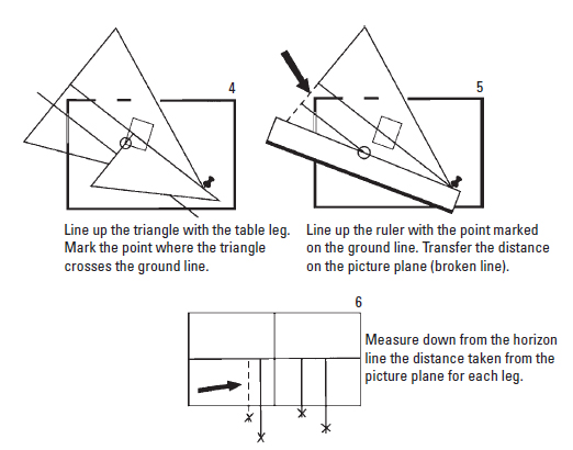
Figure e2.28 (Drawing courtesy of Steven D. Katz.)
In Figure e2.28, use the step 2 method to locate the distance from the horizon line to the point at which each table leg touches the floor.
In Figure e2.29 find the vanishing point on the horizon line for the table legs. That vanishing point is used in a moment to complete the table top. In Figure e2.30 first consult the elevation and find that the table is 2 ft high.
Using the step 3 method on the projection frame, angle the ruler to divide the vertical distance for one of the table legs into 1-ft increments. Mark the 2-ft point, which is the top of the table for that leg.

Figure e2.29 (Drawing courtesy of Steven D. Katz.)

Figure e2.30 (Drawing courtesy of Steven D. Katz.)

Figure e2.31 (Drawing courtesy of Steven D. Katz.)
Moving to the next projection frame, connect this new 2-ft point to the vanishing point; this locates the table leg behind the one just established. Do this again on the opposite side of the table. (It is important to remember that since the table is not parallel to the walls, it has different vanishing points.)
That’s it! The outline of the table is complete. Adding details to the table and the other elements in the room produces the finished drawing in Figure e2.31. In an actual plan and elevation, all of the details can be obtained and transferred in scale without resorting to the three-step method. Once the basic geometry and outline of the room have been established, door and window frames can be estimated and drawn in. Usually this is accurate enough for projecting a viewpoint for the director, though it is possible to painstakingly transfer every point for greater accuracy.
Back Projection
[Not to be confused with the rear-projection composite process.]
It is also possible to reverse the projection process so that a photograph or enlarged cine frame of a location can be “back projected” to create a plan, finding the camera position and determining the lens used, tilt angle, and so forth. This is sometimes necessary when needed measurements are not taken on location or if the location is inaccessible or no longer exists.
[This technique assumes that the walls in the photo are perpendicular to each other. Accurate reconstruction of lens and tilt information depends on the frame being uncropped. The full dimensions of a cropped frame can be estimated if sufficient information is available about the camera used.]
This technique relies on the method for locating vanishing points shown in Figure e2.20 for front projection. Review as needed before reading the following discussion of back projection.
Procedure
For the sake of clarity the line drawing in Figure e2.32 will be substituted for a photograph. Begin by placing a piece of tissue paper over the photo. The tracing paper should be several times larger than the photo so there is sufficient room to draw in the plan.

Figure e2.32 (Drawing courtesy of Steven D. Katz.)
Next find the vanishing points where the line of the ceiling and floor meet (the dotted lines) as shown in Figure e2.33. Draw a horizontal line between the vanishing points. This is the horizon line and also the picture plane.

Figure e2.33 (Drawing courtesy of Steven D. Katz.)
As in Figure e2.34 draw a vertical line down the center of the photo crossing the horizon line and extending below the photograph. This is the center of the camera angle. Now position a large 90-degree triangle so that the edges touch both vanishing points and the right angle touches the camera angle center line simultaneously. The point where the triangle meets the center of the camera angle is the station point. (If the walls are perpendicular, the vanishing points are therefore 90 degrees apart on the horizon.) The station point is where the camera was located. Place a pin here.

Figure e2.34 (Drawing courtesy of Steven D. Katz.)
[Assuming it’s a known film format, it may not be necessary to go farther than this. There is now enough information to answer the most common question: Which lens was used to make the photograph? Measure the distance between the vanishing points and measure the width of the image. Divide the distance between the vanishing points by the width of the image. Let’s say the image width is 0.444 of the distance between vanishing points, which is known to be 90 degrees. Therefore, the width of the image is 40 degrees. With a table of lens angles for the film format in question, look up the focal length of a lens with a 40-degree horizontal angle. With the vertical angle belonging to the same lens, it’s simple math to estimate the camera tilt by measuring the distance between the center of the image and the horizon line.]
Now there’s enough information to begin plotting points. This is just the reverse of the procedure from front projection. The first task is to find how far the corner of the room is from the center line. Do this by lining up the ruler so that it touches the station point (the pushpin) at the lower end. At the top end pivot the ruler so that it touches the vertical wall line at the corner of the room where it crosses the horizon line (Figure e2.35).

Figure e2.35 (Drawing courtesy of Steven D. Katz.)
Next add the ground line (Figure e2.36). Remember that the ground line is placed at a distance from the vertical center line equal to the distance of the camera above the ground. Unless the camera height is known, it must be estimated. Judging from the photograph, the camera height appears to be below eye level, or at about 4 ft. Since a typical door height is 8 ft, it’s a good clue to both the scale of the building and the height of the camera.

Figure e2.36 (Drawing courtesy of Steven D. Katz.)
The scale of the drawing may be set to any desired ratio. For example, at 1/16-inch scale, the ground line would be placed 1/4 inch from the center line.
Now it’s time to find where the corner of the room is located in the plan (Figure e2.37). Begin by using dividers to measure the distance from the horizon line down to the floor at the corner of the room.
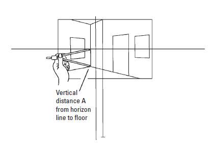
Figure e2.37 (Drawing courtesy of Steven D. Katz.)

Figure e2.38 (Drawing courtesy of Steven D. Katz.)
In Figure e2.38 the vertical distance measured with the dividers is transferred to the horizon line. Use a straightedge to line up this new point and the station point. Mark where the straightedge crosses the ground line as indicated by the arrow.
In Figure e2.39 both points have been located. The black dot is the height point located in Figure e2.38. The broken line represents the ruler line located earlier in Figure e2.35. To make the next step clearer, a detail drawing shows an enlarged view. The drawing shows a 90-degree triangle lined up so that it crosses the ground line at the height point (black dot). The intersection of the triangle’s horizontal edge and the dotted width line (circled point) is the location of the corner of the room on the plan.

Figure e2.39 (Drawing courtesy of Steven D. Katz.)
Use the vanishing point shortcut to locate the walls of the room (Figure e2.40). The shortcut works because the lines connecting the station point to the vanishing points (broken lines A and B) are parallel to the walls of the room. Therefore, by placing a 90-degree triangle on the corner point just plotted and positioning it until the edges of the triangle are parallel to lines A and B, the walls of the room are properly oriented in the plan.

Figure e2.40 (Drawing courtesy of Steven D. Katz.)
Next locate the doors and windows in the plan, as shown in Figure e2.41. Using a straightedge, draw lines from the station point to the sides of the windows and doors where they intersect the horizon line. The point where these broken lines cross the walls of the room on the projected plan locates them in correct proportion. Because certain architectural features such as doors have predictable dimensions, it’s not difficult to estimate the size and placements of objects in the room. Most doors are approximately 30 inches wide, so measuring a doorway with a scale ruler will reveal the scale of the plan. With that information it’s easy to determine the width of windows, the size of furniture, or any other width and depth dimensions.

Figure e2.41 (Drawing courtesy of Steven D. Katz.)
That’s all there is to it. The finished plan is a relatively accurate orthographic plan of the photographed space. Figure e2.42 shows lines drawn from the station point to the edge of the photograph at the horizon line. This is the camera angle for width. Measuring that angle with a protractor shows that it is 40 degrees. Dividing the width dimension of the photo by the height dimension yields an aspect ratio of 1.444. This is not equivalent to any motion picture format, but it can be cropped vertically to a 1:85 aspect ratio or any other. It is the horizontal camera angle of 40 degrees that defines the focal length camera lens needed to cover this space with the same perspective. The table for lens angles in the 1:85 ratio shows that a 30mm lens has a width angle of 39.5 degrees. That’s close enough. It’s now evident that this photo could be duplicated in this space using a 30mm lens.

Figure e2.42 (Drawing courtesy of Steven D. Katz.)
Camera Angle Templates
While it is possible to project a perspective drawing using any camera angle, a few basic lens choices are used most of the time. The five most commonly used focal lengths are listed below for two film aspect ratios. Using a protractor, these angles can be drawn on white paper (or in a CAD program) and turned into 8½ × 11 transparencies on an inkjet printer. These lens angle transparencies make short work of creating tracing paper overlays for traditional drafting.
1.85 Flat Wide Screen |
|
| 25mm – Width angle = 48 degrees | Height angle = 26 degrees |
| 30mm – Width angle = 39.5 degrees | Height angle = 21 degrees |
| 35mm – Width angle = 34 degrees | Height angle = 18 degrees |
| 50mm – Width angle = 24 degrees | Height angle = 13 degrees |
| 75mm – Width angle = 16 degrees | Height angle = 8.6 degrees |
2.35 Anamorphic Wide Screen (35mm Panavision) |
|
| 25mm – Width angle = 82.8 degrees | Height angle = 41 degrees |
| 30mm – Width angle = 72.6 degrees | Height angle = 34.6 degrees |
| 35mm – Width angle = 64.5 degrees | Height angle = 29.8 degrees |
| 50mm – Width angle = 47.6 degrees | Height angle = 21.1 degrees |
| 75mm – Width angle = 32.8 degrees | Height angle = 14.2 degrees |
1 Reprinted from Film Directing Shot by Shot, © 1991 Steven D. Katz. Published by Michael Wiese Productions, www.mwp.com