
PERFORMANCE AND MOTION CAPTURE
WHAT IS MOTION CAPTURE?
John Root
Motion capture is the process of encoding motion from the real world into the digital medium in three dimensions. More simply, motion capture is a technique for measuring things. Used cleverly, it can be used to measure the motions of the human body. Once recorded, that motion can be used to drive a digital character or breathe life into inanimate objects. Performance Capture is a term that usually refers to a subcategory of Motion Capture where an actor’s face and body performance are recorded simultaneously.
Motion capture has become a widely used technique in visual effects for its ability to deliver high-fidelity character animation in a time frame not practically achieved through other methods. While many technologies fall under the umbrella of motion capture, including piezoelectric, magnetic, inertial, radio-frequency, resistance, and a wide range of computer vision techniques, the most prevalent is a form of computer vision called passive optical, discrete point capture, or just optical for short.
The term passive optical refers to the white spheres that are being captured by high-speed digital cameras. These balls, called markers, are passive in that they do not emit light or any other information. Discrete point capture refers to the fact that the system is returning three-axis, positional information for each marker on each captured frame. The practical upshot being that a motion capture system can record the position in space of the markers on the motion capture stage.
This chapter delivers a broad spectrum of information regarding motion capture technology, techniques, and process.
The number of different technologies available to capture motion makes it almost impossible to meaningfully cover all of them in a single chapter. This chapter, therefore, focuses primarily on the most prevalent form of motion capture, optical. Where possible it will cover alternate and variant technologies.
OTHER TYPES OF MOTION CAPTURE
John Root, Demian Gordon
Motion capture is simply a tool for measuring real-world motion and encoding it into a digital medium. Therefore, a very patient man with a ruler could be said to be a form of motion capture. Optical motion capture may not be appropriate for all productions. This section serves to inform readers about alternate technologies that might be worth exploring given their unique project needs.
Resistance-Based Technologies
• Potentiometer: Analog potentiometers measure conductivity and convert it to a digital signal. By using a variety of potentiometers, it’s possible to create a wearable exoskeleton that can record its own movement.
Examples:
Gypsy-6 from Animazoo
Cyberglove from Immersion
• Light: Light is shone down fiber-optic cables, and the amount of light that hits the far end and comes back to the emitter is measured and converted into data that relates to how bent the cable is.
Examples:
Shape Tape from Measure and
5DT Data Glove from 5DT
• Piezoelectric: Piezoelectric motion capture systems work by measuring the electrical charge given off by a piece of piezoelectric material. The more the piezoelectric strip is bent, the more electricity it gives off.
Electromechanical-Based Technologies
• Gyroscopic: Gyroscopic motion capture systems use an array of gyroscopes to detect movement. Usually multiple gyroscopes are used per rigid object being tracked, to determine orientation. Examples:
Playstation 3 6DOF controller from Sony
IGS-190 from Animazoo
• Accelerometer: Accelerometers measure motion relative to a known starting position or velocity. An accelerometer can be as simple as a spring, fulcrum, and counterweight. To increase fidelity, accuracy, and repeatability, an accelerometer is often augmented with additional technology. For instance, by reading the conductivity of the spring as it expands and contracts, more information can be gleaned from the mechanism.
Examples:
Wiimote from Nintendo
iPhone from Apple
• Magnetic: A magnetic field is generated from an emitter. Sensors are then introduced into the field that cause magnetic disturbances. The position and orientation of the disturbance can be measured. By placing sensors all over an object and placing the object inside the magnetic field, the movement of the object can then be tracked over time.
Example:
Flock of Birds from Ascension
Computer Vision
• Dense stereo: Cameras are arranged in stereo pairs, which is to say they are placed about the same distance apart as the human eyes are from one another. The overlapping views from the cameras are analyzed and each matching pixel in the resulting camera images can be reconstructed into a 3D point cloud. Examples:
Di3D from Dimensional Imaging
Contour from Mova
• Structured light: A structured pattern of light is projected onto an object. Several cameras record images of the structured light pattern as it is deformed on the surface on which it is projected. The details that make up the structured pattern are triangulated by comparing the various images that were recorded. This data is then reconstructed into 3D geometry.
Example:
MaMoCa from MaMoCa
• Light stage: The subject being measured is placed into a light-controlled environment where the timing and direction of light, as it strikes the object being captured, can be measured. The light stage then emits light from the top, bottom, left, right, front, and back of the object. The resulting images are analyzed to determine the normal amount of displacement at each pixel. This information is used to create a normal map that can be used as a displacement map to increase the resolution of the basic 3D shape that was generated by the structured light scan.
Example:
ICT from Aguru Images
Time-of-Flight Technologies
• Light: The time that it takes light to be sent out and return to an emitter is measured and turned into a distance calculation that can be triangulated. A single time-of-flight measurement system generates 3D depth and 2D shape measurements. Multiple emitters are required to generate 3D shape and depth. Example:
Swiss Ranger from Mesa Imaging
• Sound: Ultrasonic emitters and detectors are utilized. The emitters send out an ultrasonic chirp that is detected by the detectors. The amount of time it takes for the chirp from an emitter to reach the detector array can be measured. The amount of time it takes for the sound to reach each detector can be equated to the distance away from the emitter that each detector is.
Example:
IS-900 virtual camera from Intersense
IS MOTION CAPTURE RIGHT FOR A PROJECT?
John Root, Scott Gagain
Motion capture is still a relatively new tool in the world of entertainment and already it has opened up a treasure trove of creative capabilities. During the past 15 years or so, motion capture has risen to become ubiquitous as a de facto content creation tool for the visual effects community. So is motion capture right for a project? To figure that out, it’s important to first recognize the role that motion capture can play in a production.
The most common use for motion capture is to capture human motion and apply it to a digital double. In this manner, high-fidelity character animation can be delivered at a price point and in a time frame not practically achievable by other methods. Using motion capture, virtual actors or fantastic characters can be convincingly integrated into live-action backplates or into digital environments where they previously did not exist such as in The Curious Case of Benjamin Button (2008). Actors can be made to play non-human characters such as Andy Serkis playing the starring role in King Kong (2005). The scope to which this technique can be extrapolated and executed is near limitless, such as in the marauding waves of Orcs in Lord of the Rings: The Return of the King (2003). Entire films can be made with motion capture such as Disney’s 2009 A Christmas Carol. Motion capture can even be used to replace actors who are no longer available or even alive!
However and perhaps most importantly, even though a production may benefit from motion capture, that does not mean it is ideally suited to accommodate it. The following points should be considered:
• What are the basic production requirements?
• What is the proper entry point?
• Which technology best suits the production needs?
• Does the production have the right resources available to meet expectations?
What Are the Basic Production Requirements?
Most successful projects go through a substantial amount of preplanning before the actual production wheels can get moving. This is true for all types of media whether it be commercials, feature films, music videos, television shows, or video games. Once the storyline has been accepted, it may be storyboarded or previsualized, at which point decisions must be made as to how the vision will be realized. If something can’t be done in the live-action arena, a number of options are available to help bring an effect to life. This is typically where the “Is motion capture right for the project?” question comes into play. The biggest factor to weigh is whether the desired animation outcome is a lifelike look or something more stylized. Motion capture or hybrid MoCap keyframed approaches are ideal for scenarios where more lifelike performances are desired.
What Is the Proper Entry Point?
Once the decision to use motion capture has been made, additional questions need to be addressed: What type of budget is available? Should a system be purchased, or should the motion capture be done by a third-party service provider? Perhaps a stock motion library is appropriate? Finding the right entry point is important. The size of the project, what the company is looking to accomplish, and the company’s future MoCap needs are all deciding factors.
What Are the Budgetary Constraints?
If price is not an issue, the company may look into building out a facility and purchasing its own system. If the company doesn’t have extremely deep pockets and a long-term production forecast, it may be better to outsource the project to one of the many MoCap service providers. A range of cost-effective options is available that can help provide a good starting point in the world of motion capture.
Motion capture equipment, especially optical, is expensive. Not only are there significant up-front costs, but motion capture equipment needs a stage area and people to run it. Properly managed, however, it’s worth its weight in gold. A top of the line system will last 6 or 8 years or more before it becomes obsolete. If the company plans on using motion capture heavily during the next 6 to 8 years, purchasing a system will definitely pay off.
Some hardware vendors will entertain leasing a system, but this is not common.
Should the Work Be Outsourced?
A number of companies offer motion capture services. The benefit to outsourcing is of course to skip all of the up-front costs associated with purchasing a system. If the project is in need of some motion capture, but a long-term investment does not make sense, outsourcing is probably the best choice. MoCap service providers can typically provide anything from raw data capture, which can be processed in house, to complete ready-to-render animation.
Should a Stock Motion Library Be Used?
Many animation libraries are available. These are collections of animated motions pertaining to a specific genre or character type. Motion libraries are typically used for crowd simulations or ambient background characters.
Stock motion libraries suffer from nonexclusivity and are often incomplete for the needs of a professional production.
Which Technology Best Suits the Production Needs?
The technology to choose should be based on what needs to be captured. Optical systems such as Vicon and Motion Analysis are the most widely used in the industry because of their accuracy and flexibility. Optical systems have become a trusted resource for visual effects professionals around the globe during the past decade. They have been battle tested for years and have proven to withstand just about any production scenario. If the production requires extreme attention to detail; multiple character interactions; highly accurate data; high-impact stunts; on-set, real-time, full-performance (face, body, and fingers), dialogue-driven sequences, etc., then the best possible option would be to use a passive optical system either in house or with a third-party vendor.
However, if the project is dependent on real-time performance or being streamed live for network television; has heavily occluded animation (i.e., shot inside a car or under bed sheets, etc.); is capturing facial animation only; or involves animated cloth, it may be better to use an alternative MoCap solution from a vendor like PhaseSpace, Moven, Animazoo, Mova Contour, Image Metrics, Measurand, or Dimensional Imaging.
Are the Resources Available?
Whether data is outsourced or captured internally, a fair amount of post-processing is likely required. Processing motion capture data can run the gamut of skill sets. Some parts of the pipeline are fairly objective, while others are highly subjective. The types of talent required will range from highly specialized animators to trackers and solvers.1 Do not take these people for granted. Ensure that the company has secured the services of skilled artisans. Do not underestimate the ability of someone skilled in working with motion capture—they can, will, and have made the difference between quality data and a useless mess.
PREPARING FOR MOTION CAPTURE
John Root, Demian Gordon
Stage time can be very expensive. Actors, directors, cameramen, grips, props, and all of the expense that comes with a typical production add up really fast. However trackers, solvers, riggers, animators, and all of the expense of the post-shoot team aren’t exactly cheap either. Because the post-shoot team is trying to re-create what happened on stage, they are at the mercy of what happened on the stage. This section explores how to minimize stage time while still providing the post-shoot team with quality data.
Understanding the technology, showing up prepared, and working with skilled motion capture professionals are all essential to quality motion capture.
What Can Be Captured
Motion capture is ideal for real-world timing of objects, people, and things moving in a 3D space. Weight, timing, balance, velocity, and acceleration are just some of the things that can be acquired with motion capture. With motion capture it is possible to record human and animal performances. Body, face, fingers, articulated puppets, and to some extent cloth can all be captured. It is even possible with some technologies to record the shape and texture of the object along with the articulated motions.
What Cannot Be Captured
Each technology has its limitations. Optical motion capture, for example, is vision based and therefore requires line of sight to prevent marker occlusion. It requires controlled lighting conditions, including reflections and refractions. Additionally, passive optical systems are marker based and are therefore limited to capturing things to which a marker can be affixed. This makes eyes difficult to capture. Further, an object’s motion needs to be able to be expressed as a point or several points in space. This makes water and cloth difficult to capture.
There are, however, lots of different capture technologies, each with different limitations. To date, no one technology can do it all without significant limitations. It is common in motion capture to combine technologies into a larger, more complete package. For instance, you could capture face and body separately or employ several types of capture devices: one for body, one for face, and possibly another for hands or eyes. Using various scanning or photogrammetry2 techniques to acquire a mesh that is later driven by motion capture is also common. Knowing the limitations of the technology is the key to success.
Motion Capture People
Motion capture is not a turnkey solution. Talented people are needed to run the hardware and to process the data. At each step in the motion capture pipeline, a different skill set comes in to play. Any production gearing up for a motion capture shoot should be sure to include hardware technicians, trackers, solvers, and animators skilled in working with motion capture data.
Hardware Technicians
Running the stage and operating the motion capture equipment is mostly an objective process. A hardware tech should be comfortable in a stage environment, have a cool demeanor and be an absolute ace when it comes to troubleshooting hardware issues. If the hardware goes down in the middle of a shoot, a lot of money will be wasted as the production sits idle. Hardware techs are responsible for ensuring that the capture technology is running like a well-oiled machine.
Motion capture hardware techs are also responsible for setting up the system. This benefits greatly from a strong knowledge of computer vision, camera technology, networking, general computer technology, and some light programming and scripting.
Trackers and Solvers
Once the data is captured, it needs to be processed. Processing optical data is usually broken into two steps, tracking and solving. Tracking is the process by which data from the stage is made usable for solving. A tracker is typically a person with strong technical skills and a keen eye for animation. Technical or junior animators with a strong ability to learn new things can make good trackers.
Solvers are the people who turn tracked data from the stage into actual character animation. A solver is typically an animator with a strong technical background. Riggers or Character Setup Technical Directors (TDs) with a keen eye for animation can also make good solvers.
MoCap Animators
Once data has been solved, it becomes character animation on a rig. At this point it is typical to want to modify the performance, which requires an animator. Finding an animator who can work with motion capture is important. It is also important to be clear when hiring animators that they will be working with motion capture because some animators prefer not to work with motion capture.
Service Providers
When a long-term investment in motion capture is not an option, it is typical to use a motion capture service provider. A service provider is a company or individual with which motion capture can be outsourced. Most providers offer services ranging from a complete solution to isolated tasks depending on need. Isolated tasks might include consultation, capture, tracking, solving, and integration. A complete solution would mean the delivery of animation to spec in a ready-to-render state. Some service providers are better than others. You are encouraged to shop around and ask lots of questions. Get lots of quotes and request sample data. Don’t be afraid to ask for a test capture session.
Most large VFX houses will offer some level of motion capture capability. Additional studios include, but are not limited to:
| Accel Animation Studios | Animation Vertigo |
| Thiruvananthapuram, India | San Diego, CA, USA |
| www.accelanimation.com | www.animationvertigo.com |
| Black Powder Media | CaptiveMotion LLC |
| Los Angeles, CA, USA | Tempe, AZ, USA |
| www.blackpowdermedia.com | www.captivemotion.com |
| Centroid 3D | Critical Moves USA |
| Buckinghamshire, UK | Detroit, USA |
| www.centroid3d.com | www.criticalmovesusa.com |
| Deakin Motion Lab | EA Motion Capture Studios |
| Melbourne, Australia | Vancouver, Canada |
| www.deakin.edu.au/motionlab | www.mocap.ea.com |
| Elektrashock | Giant Studios |
| Venice, CA, USA | Atlanta / Los Angeles, USA |
| www.elektrashock.com | www.giantstudios.com |
| House of Moves | Imagination Studios |
| Los Angeles, CA, USA | Sweden |
| www.moves.com | www.imaginationstudios.com |
| Just Cause | Metricminds |
| Los Angeles, CA, USA | Frankfurt, Germany |
| www.for-the-cause.com | www.metricminds.com |
| Mobility Art Studios | MoCap Latte |
| Hyderabad, India | Washington, D.C., USA |
| www.mobilityart.com | www.mocaplatte.com |
| MocapLab | Motek Entertainment |
| Paris, France | Amsterdam, Netherlands |
| www.mocaplab.com | www.motekentertainment.com |
| Motion Analysis Studios | Motion Werx / Animazoo USA |
| Hollywood, CA, USA | Emeryville, CA, USA |
| www.mastudios.com | www.motionwerx.com |
| Motus Digital | Parallax 360 |
| Dallas, TX, USA | Southfield, MI, USA |
| www.motusdigital.com | www.parallax360.com |
| Perspective Studios | Rainmaker Entertainment Inc. |
| New York / Santa Monica, USA | Vancouver, BC, Canada |
| www.perspectivestudios.com | www.rainmaker.com |
| Red Eye Studio | Sony Computer Entertainment of America |
| Hoffman Estates, IL, USA | San Diego, CA, USA |
| www.redeye-studio.com | |
| Xtrackrz | |
| Culver City, CA, USA | |
| www.xtrackrz.com |
Rigging for Motion Capture
Character rigging can mean many things, but for the purpose of this chapter it means the adding of controls to a digital character such that a mesh is made to be easily animated. To drive a digital character with motion capture, it will need to be rigged first. The rig is typically a simple hierarchical collection of forward kinematic pivots represented as joints or bones on which the captured data is solved. Rigging and solving are closely intertwined. Each must take the other into consideration for optimal results.
Motion capture rigs should be lightweight and straightforward. More complicated deformation and animation rigs are typically kept separate for compatibility and flexibility and then driven by the motion capture rig via constraints or remapping of the data. Compatibility is important when it is common in motion capture to involve many different software packages, each with its own limitations.
If real-time previsualization will be used during the motion capture shoot, the rigs must be sorted out beforehand. Otherwise, the rigging process can happen after and, in fact, be informed by the captured data.
Joint Placement
Creating a digital skeleton that closely matches the proportions of the actor is important to generating quality animation. However, a human skeleton is not rigid. Its pivots are speculative and often involve compound motions. Further, short of an X-ray the joint positions of the capture subject cannot easily be known because they are covered by muscle, skin, and the motion capture suit. For these reasons the range of motion is used. A range of motion, commonly referred to as a ROM, is a motion capture exercise whereby an actor is asked to move each of his or her limbs to their extremes such that the motion capture software can learn the physical limits of each limb. Some software uses the ROM to generate a skeleton automatically. If no such software is available, a skeleton is typically generated manually by visually analyzing the ROM.
Degrees of Freedom
Degrees of freedom (DOFs) are the prescribed axis by which a joint is allowed to move. Motion capture is commonly solved to six basic degrees of freedom: translation in x, y, and z and rotation in x, y, and z. It is typically not desirable to allow a joint complete freedom on all axes. For instance, knees and elbows are often solved as hinge joints. Different solving methods work better with different, degrees of freedom.
Mesh Deformations
While it is best to keep complex deformations separate from the motion capture rig, it is usually desirable to have a visual representation of the character beyond the skeleton. The mesh the skeleton is driving should be segmented, parented, or a simple smooth bound skin. This is because the various motion capture software packages do not support more complicated deformation techniques.
Shotlist
A shotlist is a document that is prepared before the motion capture shoot. The purpose of the shotlist is to predetermine everything that is going to be captured for the sake of minimizing stage time into a focused shoot. A good shotlist will list those performances in an order that plays into the technology and the stage requirements. A great shotlist will be flexible and expandable because quite often most of the information contained within a shotlist is actually filled in on stage. It is typically the job of the script supervisor, assistant director, or director to extract a shotlist from the script. Shotlists generally contain file names, brief descriptions, and important technical information.
Technology Considerations
For the most part, motion capture is liberating to the shooting process. Camera, lighting, and exacting specifics can be figured out post-shoot. There are, however, a few things to consider.
Time
There is commonly an upper limit to the length of a take when dealing with motion capture. Find out what this length is and be sure to take it into account when breaking out a shotlist.
Wardrobe
If actors are expected to be getting in and out of stunt gear or similar such wardrobe changes, it would be a good idea to group those takes together because the marker positions on the actor will likely change as the wardrobe changes.
Set
Tearing down and building up a set on the motion capture stage can be time consuming, complicated, and in some cases dangerous. If possible, shoot everything in that set before moving on.
Scene, Setup, Pass, Take
The filename is generally concatenated from the relevant information. In a feature film environment, this might follow the scene, setup, pass, take nomenclature, where each bit is separated by an underscore or dash. It is ideal to pad the individual parts such that they sort properly in a list.
002_B01_001
In this example, scene 2 is ready to be recorded using stage setup B01 (Bravo 1). This will be take 1. It might not have been known at the time the shotlist is created that a setup B was even required. However, because of the concatenation this filename is flexible and expandable.
Tiles
When breaking a script into a shotlist it is important to consider the limitations of the technology. The size of the volume3 will be limited, as well the number of actors and perhaps even the types of motion. For these reasons scenes may need to be broken up into multiple tiles. A tile is an action that is intended to be composited with other actions. For instance, technology may limit a shoot to 10 actors in the volume. Therefore, shooting a large-scale battle scene might seem impossible. In this case several tiles are invoked where the actors are playing different characters in each tile. Then, in post, all of these tiles are composited together in 3D to create the desired masses. In another example, an actor might have to run a distance that is farther than the capture volume permits. In this case, tiles are invoked, and the resulting animations are stitched together in post such that the actor is playing the same character only in a different time and space.
Actors
When casting for motion capture talent, it is helpful to cast for individuals who have excellent body control and a highly developed sense of physical awareness. The technology can be very demanding. Cast actors who will be comfortable in very tight suits surrounded by technology. And above all, look for actors who can remove their mind from the motion capture set and bring it to the story world because the motion capture set is limited in its props and set decoration.
Ideally, actors should be of the same size and shape of the character they will be playing. Following these simple rules will reduce time in post and save money. However, unlike traditional filmmaking, this is not required. The magic of motion capture is that it is possible for actors to play characters of completely different proportions to their own, at different ages, and in different times, scales, and states.
In traditional optical motion capture, some types of actors are more difficult to capture than others. Overweight actors, for instance, can be difficult to record as the markers tend to jiggle on the soft tissue rather than measure the bones and joints directly. Also, very small people can be difficult because they can present challenges to marker placement.
Briefing the Actor
It’s sometimes challenging to prepare actors for the experience of motion capture. The technology involved can be overbearing to them or it may take them a little while to acclimate to the difference between normal filmmaking and motion capture. Primarily they need to be made aware of the technology and processes surrounding them. Explain what things are, how they work, and what they do. Explain the limitations of the technology. For instance, explain that the markers should not move; explain that the cameras are extremely delicate and should not be touched; explain that a proper T pose4 is important and to respect the boundaries of the capture volume. Typically it is the job of the assistant director to brief the actors on such things but this might also fall on to the motion capture supervisor or stage lead.
Often, several technical actions must be captured that are not related to the performance but are required for the technology. These actions, such as the ROM or FACS,5 should be explained ahead of time such that they are rehearsed and taken seriously. Let the actors know that a proper ROM and FACS session is essential to good data on the back end.
Animals
It goes without saying that an animal’s natural habitat is not that of the sterile, high-tech motion capture studio. They hate having things glued to them, they hate wearing tight suits, and they are not very good at performing rigidly perfect moves such as the T pose of a FACS session. For these reasons and countless others, animals make poor motion capture subjects. That said, they can be captured like anything else. Their articulate joints can be measured with strategically placed markers just like those of the human.
A human can be instructed to not touch the markers. They can be made aware that the markers are meticulously placed and should not be moved. Animals don’t listen so well in this regard. For this reason, it is best to have a motion capture suit custom made for them with the markers sewn into the suit such that they cannot be easily removed ... or eaten. This suit should be tight, such that the suit itself doesn’t move and the markers stay true to the joints they are measuring. Of course, the suit should not be so tight that it disturbs the animal.
If custom making a tight suit is not an option, affixing the marker directly to the animal is the next best option. This is best done with a medical-grade, hypoallergenic adhesive. If applicable, and possible, shave the animal’s fur/hair such that the marker can be glued directly to the skin. If shaving the animal is not an option, fur/hair can be matted down with soluble glue and the marker then glued to the matted fur.
Animals are animals, and as such cannot be counted on to respect the technology. It goes without saying that the less obtrusive a technology, the better for animal capture. Nothing can be farther from an animal’s happy place than a motion capture studio. When shooting with animals, the set should be locked down and distractions minimized.
Suits
A motion capture suit is a tight-fitting suit to which markers are attached. They can be made from any material, but a black material with a stretchy, loop Velcro property is common. A suit should be as tight as the actor can stand it. This will keep the markers true to the joints they are measuring. However, a suit should not be so tight that it restricts the actor’s movements. Suits are typically black to reduce light reflection and prevent camera blowouts. A black suit is not necessarily required, nor is it ideal. A shiny black material can reflect light just as unfortunately as a white surface. A material that diffuses light serves the same technical requirements and is much easier to see in reference video. A video image of a bunch of actors in pitch-black suits can be difficult to discern. A good suit is worth the money because the resulting data is more usable.
Suit Slide
Even the best fitting suits are going to slide across the outside of the actor as they contort. Because the markers are affixed to the suit and not drilled into the actor’s bones directly, suit slide can make it difficult to accurately solve for joint rotations. A well-made suit will minimize the slide, but not eliminate it. When fitting an actor for a motion capture suit, it is ideal to have him or her perform a variety of motions and stretches to get an idea of where the suit is falling short. Different swatches of material can be sewn in to minimize the sliding affect. Commonly, high-quality suits have an altogether different material around the bendy parts such as the elbows, shoulders, and groin.
Marker Placement
Optical markers are placed to measure translations. Given that, markers should be placed such that when the thing they are measuring moves, the marker moves with it. Markers are primarily placed for the benefit of solving, but also need to consider tracking. Additionally, they should be placed such that they don’t endanger or hinder the performer. Markers should be placed with respect to safety and comfort over the course of the performance. The quantity of markers that can be used is limited as is the size, so it’s important to maximize these factors.

Figure 4.1 A medium-resolution, 57-marker body placement. (Image courtesy of John Root.)
Stay Rigid
Markers should be mounted rigidly to the objects they are measuring. When measuring the motions of the human body, markers should be mounted on or near bone such that they pick up the least possible muscle bulge or skin slide. When placing markers on humans, it’s important to get a good sense of the actor and suit he or she is wearing. Place markers with consideration of all the possible ways in which the actor might move and the suit might deform.
Distance
A marker defines a point in space. Any three points in space will define a triangle. A triangle defines a plane, and from a plane an orientation can be derived. Even the best marker data, however, contains errors. This error can manifest as jitter, spikes, or slip. Because of this error, the wider and larger the triangle that is created by the markers, the better the resulting rotation will be. This is because a sharp, narrow triangle will have one poorly defined axis. Any marker error on this axis will manifest as gross error in the resulting rotation. For this reason, always place markers as far from the joints they are measuring as possible and also as far from each other as possible.
Redundancy
Redundancy helps in re-creating missing or occluded markers. Through rigid body math missing markers can be gap filled during times of occlusion by placing them at their last known offset to still present markers. For this to work properly four markers per rigid segment is ideal. While gap filling with three markers or less is possible, it usually involves some kinematic or statistical knowledge of upstream and downstream hierarchical connections. Because rigidity can be speculative, the more markers placed on a rigid object, the better the gap fill will be.
Marker Placement on Faces
Not only is the human face incredibly detailed in its motion and subtleties, but the human eye is very adept at sensing its slightest movement. Capturing these motions with optical discrete point capture is difficult. This is because packing enough markers onto the face to capture every little motion presents problems for the technology, the performance, and the process. While there is no clear winning strategy, there are two common marker placement methods.
Muscle-Based Marker Placement Method
All faces are different, but under all that skin and fat, a common muscle structure can be found. One common face marker placement strategy is to lay out markers that measure the contractions of the underlying face muscles. By placing markers along the length of these muscles, the amount any given muscle is engaged can be approximated by measuring the markers’ relative distance to one another or a common point. Some muscles always flex along with other muscles and can be skipped entirely because they can be inferred from other muscles. Having captured the amount a muscle or collection of muscles is capable of flexing is only a small part of a much larger problem. Building a rig capable of using the captured muscle information is then required. Additionally, muscle bulge, fat, skin, and physics must then be modeled and rigged to build a final, photoreal face.
Advantages
• Provides a universal marker set across all actors.
Disadvantages
• Muscles can be hard to locate and capture on some actors.
• Requires complex tools to infer muscle information from point data.
• Requires complex rigs to make use of muscle information.
Peak Motion Based Marker Placement Method
Not quite as objective as a muscle-based approach would be to find independent peak motions. This means motions not easily inferred from other motions, motions whose lines of action differ from those around them. If, for instance, an actor raised an eyebrow and five folds appeared on his forehead, each fold would get some number of markers along its length. A different actor might only have three folds and therefore receive only three rows of markers. Peak motions are quite often perpendicular to the muscle motion or the result of a muscle’s motion. This is because as a muscle contracts it bulges the skin. Marker data collected in this manner is immediately usable in a direct drive or wrap deform fashion.
Advantages
• Data is more easily usable.
• Measures physics, gravity, etc.
Disadvantages
• Every actor has a different marker set.
• Time required to locate peak motions can be significant.
Hybrid Approach
A hybrid approach would be to be measure both the muscles and the peak motions. Together, information can be known that is not easily derived from either. In this method markers are placed at both the points required to measure the muscles and any motions that are caused by the muscle, gravity, or external physics. A hybrid approach that measures everything often requires more markers than can be practically captured with traditional optical markers.
• Data for all common types of solving is acquired.
Disadvantages
• Requires a lot of markers!
Marker Masks
In large-scale productions where many actors are captured across many days, it is common to create a markering template mask. This template is a clear plastic mask made from the actor’s face. Once the actor’s face has been markered for the first time, the mask goes on and is marked so as to project the markers from the face to the mask. Then these marks are drilled and holes created. Each subsequent capture day, the mask template goes on and the marker locations are projected back down. In this manner the markers’ locations do not need to be reidentified every capture day. This ensures consistency and affords efficiency.
HARDWARE
John Root, Andrew Smith
An optical motion capture system is image based and as such its primary component is digital cameras. The motion capture camera is designed for a very specific purpose: to capture a narrow spectrum of high-intensity light at very fast speeds. This light is emitted from the strobe, reflected back by the marker, and focused by the lens through the filter onto the image sensor. Then the captured image is sent by the charge-coupled device (CCD) to the CPU where it is processed, compressed, and finally offloaded to the data collection station for reconstruction. This is done typically between 60 and 240 times per second.

Figure 4.2 A high-level overview of the motion capture hardware pipeline. (Image courtesy of John Root.)
The entire motion capture process hinges on collecting quality 2D images. Bad 2D images will generate bad 3D reconstructions, so when considering hardware, collecting quality 2D images should be a primary concern. This section is intended to give a better understanding of the camera and its various elements and how to leverage them to give the best 2D data for a given application. Primarily the information contained in this section refers to Vicon and Motion Analysis hardware, but much of this information is also applicable to other systems as well, such as Phase Space and Standard Deviation.
The Strobe
Sometimes called ring lights, the strobes are the typically red, infrared, or near-infrared light-emitting diodes (LEDs) that are mounted on the front of the camera. The term strobe comes from the fact that the LEDs are flashing in unison with the camera taking pictures. This is, in most cases, happening faster than the human eye can perceive and thus they appear to be always on when in fact they are strobing. The strobes send light out that is reflected back by the marker and captured by the CCD image sensor. Picking the right strobe for the camera and lenses is important because they come in multiple varieties and can make a significant difference in volume setup.
Field of View
Field of view (FOV) is the angular extent of a scene that is illuminated by the strobe. FOV is determined by the type of LED and the orientation at which the LED is mounted on the board. Assuming all LEDs are facing forward, the only factor to consider is the FOV of the LED itself. If the LEDs are splayed outward to gain FOV, intensity will be lost because fewer LEDs will be pointed in any one direction.
The amount of light a strobe can emit will vary in both intensity and FOV. For this reason a proper lens/strobe pairing is important. This is because precious light would be wasted in the case where the strobe’s FOV exceeded that of the lens. Concurrently, if the FOV of the strobe were narrower than that of the lens, the resulting image would appear to be poorly lit around the edges. This artifact is sometimes referred to as vignetting.
Strobe Intensity
The intensity of a strobe refers to its brightness level. A strobe’s intensity is defined by the power and focus of the LEDs contained within it. The filtered strobe light has to travel to the marker and reflect with enough intensity to register on the camera sensor. Since light intensity follows the inverse square law (two times the distance equals 1/4 the light) these strobes need to be extremely bright. The intensity required for capture depends primarily on the size and distance of the fiducials (markers). Smaller volumes (capture area) generally do not require as much light as larger volumes. Strobes typically allow for brightness control and as such the brightest strobes permitted should be used.
Markers
A marker is a capture fiducial, meaning that it is a point within a captured image that can be easily identified and tracked. Sometimes referred to as jewels or ping-pong balls, markers should technically not be called sensors because there is no sensing going on in the optical marker—all of the action is at the observer.
Off-the-shelf solutions use one of three styles: passive, passive retroreflectors, and active. Though there are different styles of markers, the main goal of each is to provide something easy to identify and consistently track in the camera image. Markers are usually circular or spherical, which provides an easy-to-find center from all angles. The following types of markers all accomplish these goals by slightly different methods, and each has its niche, as dictated by application and the economics of scale.
Passive Markers
A passive marker is a fiducial that offers little to no optical advantage. Passive markers are commonly used to aid in matchmoving or live-action film shoots. In recent years passive marker motion capture has been made popular for its ability to digitally record animation simultaneously with live-action footage. A passive marker is typically of high contrast compared to its surroundings. Examples of passive markers are ink dots on an actor’s face or cross-hairs on their clothing. As such, passive markers are most difficult to track and are rarely used in conventional motion capture.
Retroreflective Markers
When people think motion capture, this is the type of marker that most likely comes to mind. Typically these markers are small rubber spheres wrapped in Scotchlite tape. The nature of a retroreflective surface is that it reflects light straight back at the source with a minimal degree of scattering. This creates tiny hot spots of light in the collected images that can be easily distinguished from background information. In this manner, markers are easily separated from the rest of the image and therefore more easily tracked.
Typical sizes include 10 to 18mm spherical markers for the body and 2 to 5mm spherical or hemispherical markers for the face. A marker’s size is primarily determined by the distance and resolution of the camera but is also affected by strobe intensity, f-stop, and the subtlety of the performance being captured. Prices range around $6 per marker, and given that a single actor may wear 60 or more just for body capture, markers are not a trivial cost that shouldn’t be overlooked. The life span of a given marker depends on what it is used for, but they can lose effectiveness over time by mishandling (particularly if you just ate some greasy pizza), scuffing, rips in the tape, and general capture. Expect to replace markers fairly frequently if stunts or if lots of action are involved.
Active Markers
The less common active marker is a tiny solid-state LED that emits the same spectrum of light the cameras are looking for. Active markers require power so are typically tethered to a battery worn by the actor. Because active markers do not bounce light, they are brighter and more clearly visible to the cameras. Active markers, however, typically emit light in a particular direction and, hence, are most visible from the direction they are facing. Light from an active marker can be diffused to cover a wider FOV but in doing so becomes less bright and can lose some of its advantages. This cone of effectiveness can induce noise in the data as cameras come in and out of view. Some hardware can detect the frequency at which active markers are strobing and automatically identify the marker’s label. This advantage makes active markers ideal for real time but with the disadvantage of an upper marker limit. It is possible, albeit impractical, to mix retroreflective and active markers in the same capture volume.
Lenses
A camera’s lens is its window into the capture volume. Motion capture requires an intricate understanding of exactly how any given lens gathers light from the volume and focuses it onto the camera’s image sensor. This understanding is known as calibration and is required so that any given 2D pixel can be traced back out into 3D space. Calibration is so delicate that a mathematically perfect lens is required for mathematically perfect data. However, such lenses do not exist. A good motion capture lens will be a lens with nearperfect radial symmetry, no filter coating in the spectrum in which the capture occurs, high speed, and as close to diffraction limited as possible. Hardware providers generally recommend and resell a variety of lenses for various volume configurations.
Focal Length
The focal length is the distance from the lens to the image sensor when the lens is focused on an object at infinity. That is, it is the number used to define the FOV of a camera’s lens. Because the size of the image’s sensor will be fixed and the parameters of the lens may vary, focal length does not directly correlate with FOV. Generally speaking, however, a wide-angle lens will have a smaller focal length number, whereas a narrow-angle lens or long lens will have a high focal length value. Focal lengths typical for a motion capture volume range from 12.5 to 45mm or anywhere in between. However, focal lengths can go as low as 2mm in special cases such as head-mounted cameras.
Generally speaking, and assuming a list of fixed parameters, long lenses are used to capture things very far away, while wide lenses are used to capture things very close. However, distance can be traded for accuracy. A long lens focused on a close object would be more accurate, but have a smaller capture volume than if the same object were being captured by a wide lens. Inversely, a wide lens focused on a far object would be less accurate but have a very large capture volume. Given these trade-offs, balancing distance and focal length against marker size and accuracy is a delicate process.
One additional thing to consider when talking about focal length is camera handoff. Camera handoff occurs when a marker is well inside the capture volume, but leaves the view of a camera. While this marker is still being seen by other cameras, the resulting position of the marker will suffer from its number of contributing cameras having changed. For this reason, simply throwing more cameras with long lenses at a volume does not necessarily make it better.
F-Stop
The f-stop of a lens is focal length divided by the aperture diameter. In practical terms it defines the amount of light that is let in through the lens. This is done by adjusting the aperture, which is a mechanical iris. Closing this iris, referred to as stopping it down, reduces the amount of light captured, while opening this iris allows more light in to be captured.
It is ideal, in the world of motion capture, to be taking pictures that are a frozen instant in time. This means using very fast shutter speeds. Faster shutter speeds capture less light. For this reason it is common to open up the f-stop to let more light in. This, however, has the negative by-product of decreasing the depth of field, meaning objects are out of focus. Balancing f-stop with strobe intensity and shutter speed is a delicate process.
Depth of Field
While not a property of the lens, depth of field (DOF) is closely related to the lens settings. While a lens can only truly be focused on one point in space, the DOF refers to the acceptable distance from that point where an object is still considered to be in focus. Naturally, a deep DOF to increase the range where markers are in focus is preferred. To obtain this, it is typical to stop the aperture down, thereby letting less light in. However, decreasing the amount of light let in to the camera makes for a darker image of the marker. Ideally, markers should be in focus to a camera at the farthest extent of the capture volume while also being fully lit. Finding this sweet spot is a balance between f-stop, strobe intensity, and shutter speed.
Prime versus Zoom
A prime lens is a lens whose focal length is fixed, while a zoom lens is a lens with an adjustable focal length. While the flexibility of a zoom lens is attractive, they should be avoided because they contain many complex elements that decrease the amount of light and increase the amount of difficult-to-calibrate image artifacts. It is possible to find high-quality zoom lenses without such aberrations, but they come at an extremely high price.
Which Lenses Are Ideal?
Which lenses to use is going to depend primarily on the number of cameras present, their resolution, and the size and scope of the markers they are trying to capture. Here are some typical system configurations:
• 20 × 20 × 10 ft, 16 cameras, 16mm focal length, 15mm marker minimum, 2 actors;
• 10 × 10 × 7 ft, 32 cameras, 24mm focal length, 5mm marker minimum, 1 actor;
• 30 × 30 × 7 ft, 32 cameras, 16mm focal length, 15mm marker minimum, 4 actors; and
• 20 × 20 × 7 ft, 64 cameras, 24mm focal length, 5mm marker minimum, 2 actors.
Filter
The purpose of the filter is to eliminate all light except that emitted from the strobe. Sometimes a filter is mounted in front of the lens, sometimes behind it. Given the retroreflective nature of the markers and the position of the strobes, the resulting filtered image should contain only bright white spots of light reflected by the markers.
Charge-Coupled Device
Light emitted from the strobe and reflected back from the marker will land on and be captured by photoelectric image sensors and transferred by the CCD to camera memory for processing. The speed and resolution of a CCD will vary based on the camera model, but it is typically in the neighborhood of 4 megapixels at 120 fps. While quality data can be collected at 1 megapixel, some cameras offer resolutions as high as 16 megapixels. The CCD is arguably the most important piece of the motion capture camera when recognizing that higher resolutions and faster frame rates have the biggest impact on data quality. In addition to the primary factors of resolution and frame rate, the shutter, gray scale, and sensitivity must be considered.
Resolution
The resolution of the camera is determined by the number of photoelectric sensors contained within the image sensor. All things being equal, resolution will have the biggest impact on data quality. This is because the circle fitter will have more pixels to work with when attempting to fit a centroid6 to any “blob” of pixels returned by the CCD. More information on circle fitting is given in the reconstruction section under Software.
A higher resolution CCD would allow a wider angle lens or finer precision with the same lens. Higher resolutions can capture smaller markers or farther distances. Higher resolution could also equate to fewer cameras. The benefits to a higher resolution are so vast that it is the single biggest factor to consider when purchasing a camera.
Frame Rate
Frame rate is the number of images captured per second. Maximum frame rate is determined by how many times per second the CCD can read from the image sensor and offload data to memory for processing by the CPU. Beyond the obvious benefits of being able to capture high-velocity actions such as the swing of a golf club, frame rate will also improve data quality. More temporal samples of a marker’s position in space will average down to a more accurate position when filtered. More on filtering can be found in the tracking section under Software.
Shutter
The image sensor is read by the CCD at the specified frame rate. Without first blanking the sensor, residual light information would be left on the sensor and would manifest itself as a motion trail in the image the next time the CCD went to read. By exposing the sensor to dark it will more quickly “forget” what it saw. This is not literally the case in many cameras. Some cameras use an electronic shutter, which blasts the image sensor with a jolt of electricity to blank the information off the sensors. A sensor outfitted with an electronic shutter is always exposed to light. In the case of an electronic shutter, the image sensor is blanked just before the CCD goes to read.
The amount of time a shutter is open before the sensor is read will affect the brightness of the image. Shutter speed is another factor to consider when trying to get a good solid image of the markers.
Gray Scale
Images taken by the camera are likely either black-and-white or gray scale. White represents the presence of the desired color spectrum, black the absence of color, and grays being the values anywhere between white and black. Black-and-white cameras take images whose pixels are either black or white, whereas grayscale cameras take images whose pixels can be one of up to 256 values between black-and-white. Some less common CCDs are capable of more than 256 shades of gray scale while others are capable of less. A CCD capable of delivering gray scale is ideal because it will unquestionably yield better data over just black or white.
A black-and-white camera has a threshold value. This value determines what brightness a pixel needs to be before it will be captured by the CCD. If a pixel is determined to be bright enough, it will leave a white pixel on the image. If it is not bright enough, no pixel will be created and the image will remain black. Black-and-white cameras are binary in this regard. One possible advantage to black-and-white over gray scale is that it’s faster to transfer and process than gray scale.
A grayscale camera, on the other hand, is capable of capturing pixels whose brightness ranges from nearly black to pure white as long as they are in the spectral range being sampled. Having this information allows the system to more accurately detect edges of markers during circle fitting, resulting in a more accurate centroid.
Sensitivity
There are two kinds of sensitivity. The first is determined by how large the photoelectric sensors are. At equal resolutions a CCD with larger sensors would result in a larger chip, onto which the lens would focus a larger image. The result is that more light will be absorbed by each individual sensor. The second kind of sensitivity is how many different shades of any given color that sensor can register. The image sensor is usually tuned to be more sensitive to a particular wavelength of light, typically red, near infrared, or infrared. By ignoring some colors, the sensor can focus its spectral resolution in the narrow band of light being captured.
Onboard Processor
Most motion capture hardware providers now offer cameras with onboard image-processing capabilities. This means that the images captured can be analyzed and processed before being sent back to the data collection station. The processing power contained within a camera will vary depending on manufacturer and model. Typical image-processing tasks include feature detection, feature identification, and compression.
Feature Detection
The process of analyzing an image in an effort to find some sort of pattern is called feature detection. Features vary based on the particular type of motion capture being deployed. However, in the case of passive optical, discrete point capture the algorithm will be looking for blobs of pixels it determines to be circular. If a blob of pixels is determined to be circular, it is probably the captured image of a marker. When a circle is detected the algorithm can discard those pixels and just retain the centroid information. By only sending a coordinate plus a radius that describes the found circle, the amount of data sent back from the camera can be dramatically reduced, affording much faster frame rates.
Feature Identification
Once a feature has been found, it may be desirable to temporally correlate its existence with similar features found on other frames. This is accomplished by first assigning an arbitrary identification to all of the markers found on a given frame. If a newly found marker on a subsequent frame is similar to a previously found marker, it is assumed to be the same marker and given the same identification. Feature identification is a key component to real-time motion capture.
Compression
Bus speed, network bandwidth, and disk access are limited, so to further enable high frame rates, motion capture cameras typically deploy image compression. Most pixel information is discarded in favor of the centroids; therefore, the majority of the pixels in the images collected are black. The only nonblack pixels would be those to which a centroid could not be fit. These leftover pixels are run-length encoded and sent back for a more complex circle fitting. Run-length encoding expresses the image as long runs of data. For instance, scanning an image from left to right, top to bottom, many thousands of black pixels would be found before encountering a white or gray pixel. Run-length encoding is a type of lossless compression.
Inputs/Outputs
A motion capture camera will have several connections in the back, for both incoming and outgoing purposes. Incoming connections will include power, networking, and sync, while outgoing information will include network and video. In some cameras these are combined into a single cable. In motion capture systems containing hundreds of cameras, cabling can be a complex practical issue as the sheer number of cables becomes difficult to wrangle.
Setup
Cameras should be mounted in a secure fashion and preferably to the foundation of the building in which the studio is housed. A sturdy box truss in a temperature-controlled room is ideal. Motion capture cameras are delicately calibrated instruments so that the slightest nudge or shift in its position can throw the resulting data out of alignment.
Balance
A motion capture volume can be configured in a nearly infinite number of ways. With all of the variables at play, configuring a volume is more of an art than a science. There are a few guidelines, however:
• It is ideal to see at least 5 pixels of resolution for a marker in a captured image.
• Marker images should have a nice full, white center with a crisp gray outline.
• Position cameras and choose lenses such that no marker is smaller than 5 pixels when inside the volume.
• A good maximum marker size for body capture is 16mm. Any larger and they start to impede the actor. Use the smallest marker that still allows for 5 pixels of resolution.
• A good marker size for face capture is 5mm. Any larger and they start to collide with each other on the face and impede the actor. Smaller markers can be captured with very specific camera configurations.
• More resolution is generally better, but that does not mean that more cameras are better.
SOFTWARE
John Root, Demian Gordon
Motion capture software can be broadly divided into two categories, acquisition and post-processing. Acquisition software is typically supplied by the hardware provider for the purpose of setting up and running the system. Post-processing software, which might also be provided by the hardware vendor but can involve off-the-shelf tools, is meant to turn the acquired raw data into usable animation for the project. Some software is capable of both acquisition and post-processing activities. This section describes each of the algorithms at play by translating the complex math into plain English.
Acquisition
Acquisition is the process of triggering the cameras to take pictures. In order for the acquired images to be meaningful, the system must be synchronized and delicately calibrated. Synchronization, or sync, is important to all forms of motion capture. Sync is the process by which all of the optical cameras are made to capture in unison. Taking synchronized pictures of an object from multiple angles and then comparing those captured images against one another is the basis of all optical and most computer vision-based motion capture technologies.
Calibration
Calibration is the process by which the intrinsic and extrinsic parameters of a camera are made known. Properly calibrated cameras are essential for quality data during reconstruction. Camera extrinsic values are the values that define the camera’s position and orientation in space. Camera intrinsic values are values required to map any given pixel of the 2D image out into 3D space. Because it is not possible to know one without knowing the other, calibrating intrinsic and extrinsic values often involves a third parameter, a calibration object. A calibration object is an object whose exact dimensions are known. By placing the calibration object in the capture volume and photographing it from multiple angles, it is possible to reverse engineer the camera parameters by assuming that what is seen is the same as what is known. This is done by performing a bundle adjustment. A bundle adjustment is a mathematical process by which a best fit of the unknown parameters is found through reverse projection and optimization of the known parameters. It is ideal to use a calibration object that defines every point in the field of view of the camera including the depth axis. For this reason, a wand calibration is typical.
Calibration should be performed regularly. It is common practice to calibrate the capture system at the beginning of each capture day and at the end. Additional calibrations should be performed if any of the camera’s intrinsic or extrinsic values might have changed, for example, if a camera is bumped or moved. Most capture systems allow arbitrary assignment of calibration files to capture files. This allows users to back apply an end-of-day calibration to some earlier capture data to account for degradation in data quality due to, for example, a slip in calibration.
Camera Extrinsic Parameters
The extrinsic parameters of a camera are the x,y,z position and x,y,z orientation of the camera in space, relative to the zero point and world scale of the capture volume. The camera extrinsic parameters can be static or dynamic. In the case of a dynamic extrinsic parameter (where the cameras are moving), calibration is recomputed per frame by either re-projecting reconstructions from static cameras back to dynamic cameras or assuming a known calibration object in the scene to be “true.”
Camera Intrinsic Parameters
The intrinsic parameters of a camera are the values needed to re-project any 2D pixel out into 3D space. These values typically include a lens distortion model, focal length, and principle point, but can contain additional parameters. If it is known exactly how a camera bends light and captures it onto its image sensor, the system can reverse project any pixel back out into 3D space and assume the point to exist somewhere along that ray.
Dynamic Calibration
Dynamic calibration is the process of capturing a moving object of known measurements, most commonly a wand. Wands come in many shapes and sizes. Typically, a calibration wand is a rigid stick with some number of markers attached to it. The exact distance of each of these markers to one another is measured and known to a high degree of accuracy. By photographing these markers from many angles, and assuming the known measurements to be true in all images, a 3D representation of the capture volume can be built and the camera intrinsic and extrinsic parameters can be calculated.

Figure 4.3 ImageMovers Digital main capture volume during a wand calibration. (Image courtesy of ImageMovers Digital.)
When performing a wand calibration, the wand is waved about the volume so as to completely cover each camera’s field of view, including the depth axis. It is also ideal, at any captured instant, for the wand to be seen in at least three cameras. Not doing so will result in poorly calibrated areas of the capture volume. These captured images of the wand are then digested by the software and an accurate model of the camera’s intrinsic and extrinsic parameters is established.
Static Calibration
While the most common form of calibration is wand calibration, some systems use static calibration. Static calibration does the same thing as a wand calibration except in a single instant. Static calibrations are performed by placing a single known object in the capture volume and capturing it from all cameras simultaneously and in a single instant. The advantage of this is that the calibration is less subject to error induced by the person performing the wand wave. The disadvantage of an object calibration is that the capture volume is limited to the size and shape of the calibration object.
Checkerboard Calibration
Some less common machine vision-based systems use a checkerboard calibration. A checkerboard calibration is similar to a wand or object calibration in that an image of a known checkerboard is put before the camera and photographed from multiple angles.
Post-Processing
Once data is acquired it must be processed in order to be made usable. With optical data this usually involves reconstruction, labeling, cleaning, and solving. Each of these steps generates data that is usable in the next step.
Some systems can acquire and process data simultaneously, thereby giving the user data in real time. Real-time data often involves shortcuts or approximations that result in lesser quality data than data derived from more complex post-processing techniques. Depending on the production requirements, real-time quality data may be sufficient.
Reconstruction
The term reconstruction as it applies to optical motion capture is the process of creating 3D data from 2D images. The software first finds all of the places in each camera’s 2D image where it detects a marker. During the marker detection phase, often referred to as circle fitting, the software is typically looking for a round blob of pixels to which it will fit a circle. Because blobs of pixels are not perfect circles the 2D position of the resulting circle’s centroid is somewhat inaccurate. Once all the circles are found across all cameras, the process of turning these centroids into 3D trajectories can begin.
Once the cameras are calibrated, the system knows how light is bent and captured on the image sensor. By reversing this path the system can shoot (calculate) an imaginary ray back out into the volume somewhere along which the marker is known to exist. By shooting many of these imaginary rays from all cameras and then looking for intersections among them, the system can begin to reconstruct 3D data in the form of discrete marker positions.
While a point can be reconstructed with a mere two intersections, more intersections are better. This is because each of these rays is somewhat inaccurate and more rays will amortize the error down to yield more accurate information. Additionally, a ray’s contribution to a marker reconstruction will be intermittent as it is occluded or leaves the camera’s view frustum. So while a marker’s position is derived from the average of its contributing rays, the number of rays contributing to this average is constantly changing, thereby inducing spikes in the trajectory.
Once marker positions are reconstructed they need to be temporally correlated such that the software can determine that a given trajectory is the same marker through time. This process, called trajectory fitting, is usually the final step of reconstruction or the first step of labeling depending on the company view of the pipeline. Trajectory fitting most commonly utilizes 3D velocity predictions but can also involve more complex 2D information from the cameras.
Labeling
Labeling is the step after reconstruction where the yielded marker trajectories are assigned names. Marker trajectories will be some number of frames long depending on the quality of the trajectory fit and the accuracy of the reconstruction. The process of assigning labels is actually correlating fragmented animation curves rather than naming individual marker points. Having labeled data is essential for the solver to know what any given trajectory is measuring. Unlabeled data, often called raw or uncorrelated, is not useful because it exists sporadically in time, blipping in and out of existence.
By incorporating some biomechanical information into the labeling process, the software can make an informed guess as to where a marker should exist. For instance, it could be said that markers on the head are always a given distance away from one another or that a marker on the wrist can be found within some rigid distance of markers on the elbow. With these sorts of rules at play, should a marker on the head or wrist disappear it’s possible to look for an unlabeled marker in a prescribed location. In this manner the more markers that can be identified, the easier it is to identify the entire set.
Gap Filling
Sometimes no marker was reconstructed. This is usually because it was occluded (no camera could see it). When this happens, the same biomechanical rules involved in labeling can be used to create a marker at the location the missing marker is thought to be. This process is called gap filling. Gap filling usually involves rigid body reconstruction but can also involve more complex biomechanical assumptions. An example of such an assumption might be informing a missing marker’s location by assuming the knee to be a hinge. In this case, there might be information about a thigh and a foot, which could be used with this assumption to reconstruct a missing marker at the knee.

Figure 4.4 The image on the left is a marker trajectory that contains a gap. In the image on the right, the gap was filled using a rigid body transform. (Image courtesy of ImageMovers Digital.)
Rigid Bodies
A rigid body is a transform derived from three or more markers thought to be rigid with one another. Imagine that any three points in space would define a triangle and that from a triangle it is possible to extract a rotation. That rotation, plus the average position of the markers would give a rigid body transform.

Figure 4.5 Any three nonlinear points in space define a triangle. From a triangle, a rotation and translation can be extracted. (Image courtesy of John Root.)
Cleaning
Optical data is unfortunately noisy. This is primarily due to inaccurate calibration, poor circle fitting, and occlusion. Whatever the cause, these errors manifest as trajectory spikes and high-frequency jitter that must be removed. This process is often referred to as cleaning. If the data is not cleaned, the spikes and noise will come through in the resulting animation.
Cleaning typically involves some amount of identification and removal of large data spikes, followed by application of a light filter, where the filter is a mathematical algorithm in which the animation is smoothed to remove noise. Many types of filters are available, but all should be used with caution because they can be destructive to the animation. Overfiltered data can look mushy and lack the subtlety and nuance that makes motion capture so realistic. Most filters benefit from high frame rates. This is because the more data they have to average or analyze, the more accurately they can distinguish between noise and performance.
Solving Motion Capture
Solving is the process of turning processed data into usable animation. Most commonly this involves manually fitting a skeleton into marker data, defining a relationship between the markers and the skeleton, and then having the solver attempt to hold that relationship over the course of the animation. Because the physical relationship between a marker and a joint can vary due to a variety of factors including joint type, suit slide, muscle bulge, and skin stretch, holding the corresponding digital relationship can be a tricky process.
Rigid Body Solvers
A rigid body solver takes groups of three or more markers that are assumed to be rigid to one another and extracts a 6 degree-of-freedom transform. Extracted transforms, in the form of joints, can be parented relatively to one another such that they describe a skeleton. Although a skeleton derived from rigid bodies might visually look correct, it typically contains transforms on undesirable axes that need to be rectified in a second step often involving constraints. Motionbuilder’s Actor solver is an example of a rigid body solver.
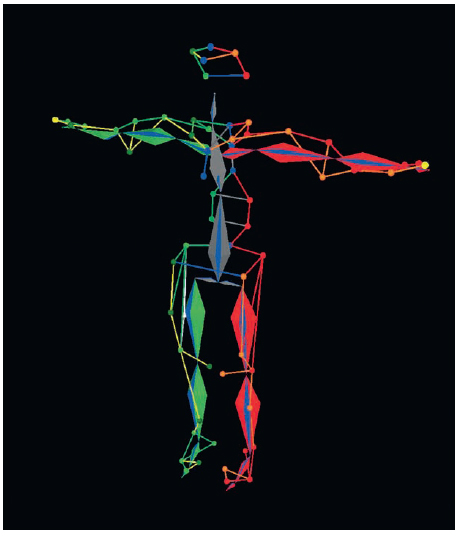
Figure 4.6 A skeleton fit into its markers using Vicon’s Blade. (Image courtesy of ImageMovers Digital.)
Constraint-Based Solvers
A constraint solver is very similar to and often used in conjunction with a rigid body solver. With a constraint solver, the markers themselves are used to directly drive the skeleton’s rigging controls, which in turn drive the skeleton. Using a motion capture marker as an IK7 handle would be an example of a constraint-based solving method. Motionbuilder’s Actor solver is an example of a constraint-based solver.
Global Optimization Solvers
A global optimization solver attempts to find a best fit for a skeleton into its marker data. The best fit is considered to be the solution with the least amount of error. Error can be described in a number of ways, but is most commonly described as variations in distance. Distance is the user-defined initial offset between a marker and a joint in the target skeleton. In this case a global optimization would attempt to animate the skeleton such that all of the distances between markers and joints are offset the same throughout time as they were in the initial user fitting. Vicon’s Blade, Motion Analysis’s Calcium, and the Peel Solver are all examples of globally optimized solvers.
Physics Solvers
A physics solver uses the marker data to actuate the skeleton in a number of ways. Once a marker is assigned to a bone, the bone might be asked to take on the velocity of that marker or to gravitate toward the marker. Endorphin is an example of a physics-based solver.
Behavioral Solvers
A behavioral solver reinterprets the marker data into a common language spoken by the rig. To accomplish this, data is analyzed and statistically strong patterns are extracted—be it FACS8 values, phonemes, emotions, intentions, or some other meaningful animation data. A behavioral solver has the advantage of being able to solve and retarget simultaneously. Behavioral solvers are typically used for the face or other nonrigid deformable surfaces where joints are inappropriate. The ImageMetrics solver is an example of a behavior solver.
FACIAL CAPTURE
John Root, Nick Apostoloff, Oleg Alexander
Facial motion capture is the younger and less developed sibling of body motion capture. Where body motion capture aims to capture and reconstruct the joint angles of an articulated skeleton, facial motion capture measures the subtler deformation of facial tissue. Perceptual motion plays a more important role in facial motion capture because it is the actor’s emotion as well as facial articulation that is required rather than well-defined skeletal motion. The importance of perceptual motion makes facial motion capture in some ways harder and in other ways easier than body motion capture. Small facial motions such as the slight squinting of the eyes when somebody smiles to a trembling upper lip offer immediate insight into the character’s emotions and are hence crucial to capture accurately. Alternatively, because the character’s face is often very different from the actor’s, the global deformation, though still important, can be represented less accurately. This leads to different requirements and techniques for capturing and solving facial motion as opposed to body motion, where perhaps the desire is to represent a skeletal motion as accurately as possible. Capture techniques can estimate a dense reconstruction of the actor’s face or compute the location of a sparse set of markers, as discussed first in this section. In both cases, complex solving techniques must be employed to translate this geometry into character animation and this is the focus of the later part of this section.
Capture Techniques
Methods for facial motion capture can be broadly divided into two categories: marker based and markerless. Marker-based methods use markers applied to the actor’s face so that a capture system can measure their motion. These markers may be in the form of optical retroreflective markers, makeup markers, or noise pattern makeup. Markerless methods simply use the actor’s facial structure as tracking features.
Marker-Based Motion Capture
By adding markers to the face, a performance can be easily and accurately captured because the markers offer a clearly delineated fiducial that can be tracked and differentiated in multiple views. A unique surface texture like this is crucial in any system where 3D geometry is created from images of an object. Given the position of a fiducial in two or more cameras, its 3D location can be computed using techniques of multiple-view geometry such as triangulation (Hartley & Zisserman, 2000). The downside of a marker-based approach is that the markers themselves can hinder a performance and impose limitations on the actors, capture volume, and the production itself.
Optical Markers
Optical retroreflective markers commonly used in combination with filtered lens cameras create easily detected features in each camera. In a similar fashion to optical body motion capture systems, the 3D accuracy is directly correlated to the number of cameras used and the size of the volume they cover. Facial motion capture is slightly more susceptible to inaccuracies because smaller markers must be used on the face than the body. To counter the inaccuracies introduced by smaller markers more cameras must be used in a smaller volume (i.e., closer to the face), which inherently restricts the performance that can be made.

Figure 4.7 Marker-based facial capture. (Image courtesy of ImageMovers Digital.)
A significant advantage of these systems is that the software used to compute the marker positions is automatic and only requires supervision by a human operator. With enough cameras in a small enough volume, very accurate results can be achieved. However, in the past these volumes have been too restrictive. Large volumes that allow simultaneous body and facial capture have usually produced poor facial data. Conversely, small volumes produce good 3D but require the facial performance to be conducted separately from the body performance.
From a robustness standpoint, a disadvantage of optical systems is that the markers look the same in each camera; therefore, it is difficult to find the same marker across multiple cameras. Remember that an object must be seen in two or more cameras to reconstruct its 3D location. In general, the more cameras that see a marker, the more accurate the 3D data will be. For this reason, calibration of the cameras in these systems is as essential as a high camera count. The calibration is important because if the positions of the cameras are known (as well as their internal calibration), it is possible to restrict where a 2D point in one camera might appear in another camera (see epipolar geometry9 in Chapter 8 of Hartley & Zisserman, 2000).
A high camera count is important for two reasons. First, there is always error in the location of a 2D point in an image (e.g., image quantization, motion blur, inaccurate marker segmentation, etc.). Though these 2D errors produce errors in the 3D location, this error can be reduced by seeing the marker in many cameras. Second, as in body motion capture, occlusion is a problem in facial motion capture. Occlusion errors manifest themselves as pops in the data, sometimes because a marker is suddenly seen by fewer cameras or because the system has mislabeled the marker across the cameras. As mentioned previously, and repeated here because it is important for reducing these inaccuracies, the number of cameras required is related to the size of the capture volume—the larger the volume, the more cameras required.
Another disadvantage of optical marker systems is the markers themselves. First, they are expensive. Second, they are difficult to apply to the skin and often fall off. Furthermore, the data captured is limited to locations where markers are present. If, after capture, it is decided that more markers around the eyes are required, it would be necessary to recapture the performance with more markers.10 For this reason, careful planning of marker locations and count is extremely important. Typically, regions of the face that deform considerably require more markers. It is also important to consider both the actor and the character when it comes to marker placement. For example, if the character does not have a nose, then there is no point having markers on the nose of the actor. If the actor has deep wrinkles around the mouth, then it would be wise to avoid placing markers on those wrinkles as they will be occluded when the wrinkles engage.
Makeup Markers
Some of the shortcomings of an optical marker solution can be overcome by using makeup markers, usually in the form of solid circles drawn on the face. Makeup markers are generally more comfortable for actors, and they do not fall off and do not hinder the performance. Makeup markers can be tracked and reconstructed just like optical retroreflective markers. However, unlike retroreflective markers, makeup markers typically require the capture of standard noninterlaced video footage. Unfortunately this can equate to lower frame rates and lower resolution because the storage of the image data can be prohibitively expensive. However, the switch to video opens up new hardware options including head-mounted cameras, and the captured video also provides an excellent animator and editorial reference. Most important, a head-mounted solution frees the actor from the restrictions of a small performance volume.
Makeup markers are most commonly used in conjunction with head-mounted cameras and these systems must be kept lightweight. The reduction in weight is usually at the expense of high-end features including on-board feature detection, high frame rates, and image compression. Some design specifications that may be important in these portable capture systems include the following:
• How many cameras to use: With special statistical models it is possible to reconstruct 3D given only one camera, but in general two or more are required.
• Frame rate for capture: Higher frame rates (48+ fps) make marker tracking easier and allow temporal filtering to be used to smooth the data, at the cost of having to store more images.
• Compression of captured images: From the perspective of marker detection, uncompressed images are the best, but this is not always practical given the storage requirements.
• Use of color versus monochrome cameras: Color can add additional texture that can be useful for marker tracking and labeling (i.e., different colored markers) but requires more data be stored.
In both the case of optical markers and makeup markers, the daily shooting schedule has to factor in the application of the markers, which can take considerable time depending on the number of markers used.
Noise Pattern Capture
An all-together different capture method employed by some in the industry to create high-resolution facial geometry is noise pattern capture. In this method, some form of noise pattern is applied to the face to create many unique features that can be tracked across multiple cameras. The noise pattern may be in the form of makeup applied in random patterns over the face or through structured light projected onto the face. Even the skin itself can be used as the noise pattern as long as the skin has enough high-contrast texture.
Some Motion Capture studios employ normal makeup while others, such as Mova Contour, use phosphorescent makeup and synchronize their cameras and lights such that every second frame is captured in the dark and the cameras see only the phosphorescent makeup. This is incredibly useful because it removes noise artifacts generated by the background in the scene and only the geometry of the face is captured. Noise pattern techniques can produce geometry with 100k+ vertices and pore level detail.
A major problem with noise pattern techniques is temporal coherence. For rigging purposes, each frame of mesh data usually has the exact same topology. While noise pattern techniques can usually produce excellent high-resolution meshes, the meshes tend to drift over time in such a way as to make them difficult to use for motion capture purposes. In addition to this, these techniques usually require complicated hardware setups that have a small operating volume. The lighting often had to be very bright, or consist of many flash units, which can be uncomfortable for the actors. Sometimes the actors may also have to remain still over a number of seconds during the capture process.
Markerless Motion Capture
The advantage of marker-based techniques lies in the method in which the markers are captured. The markers form unique signatures in the image data that can be easily detected. In the case of markerless capture, these signatures are no longer available and similar information must be derived from features inherent to the actor’s face, and more advanced techniques must be employed for their capture.
Active Appearance Models
One prominent method in the vision community for marker-less facial motion capture is active appearance models, or AAMs (Cootes, Edwards, & Taylor, 1998; Matthews & Baker, 2004). An AAM is a statistical technique that learns the appearance of salient facial features and builds a deformation model of those features so that tracking can proceed automatically. Typical features that are tracked include the eyebrows, corners of the lips, and the nose.
Once the AAM has been trained, it can then automatically capture the locations of these facial features in 2D or 3D from one or more cameras. A crucial point here is that these models must be trained. This training requires the salient facial features in many images of the actor to be hand labeled, which is a timeconsuming process. These methods are often limited to only working with the person they have been trained with and are sensitive to rotations of the person’s head. Another disadvantage of these techniques is that there aren’t many salient features on a person’s face. The eyes, eyebrows, mouth, and nostrils can all be captured, but the deformations of the cheeks and brow and the subtler motion that occurs away from fiducials are often lost (i.e., squinting).
Pictorial Structure Models
In a similar fashion to the AAM work of Matthews and Baker (2004), the pictorial structure model (PSM) work of Felzenszwalb and Huttenlocher (2003) learns a statistical model of the appearance of features and their relative motion. Like AAMs, this requires hand-labeled training data, but this is encapsulated in a robust estimation framework that computes the optimal solution given the image data. What this means is that the PSM can compute the feature locations for each frame of data with no prior knowledge of where they were in the previous frame. The AAM needs an initialization process to get started and may drift away from the correct solution over time.
Dense Stereo Reconstructions
Like the noise pattern techniques discussed previously, there are other methods that focus on computing temporally coherent dense reconstructions from two or more cameras (Furukawa & Ponce, 2009). These techniques work well with even-lit images from many high-resolution (10+ megapixel), low-compression cameras, to create the coarse geometry of the face, but they don’t typically capture the high-frequency pore-level details, are computationally expensive, and can produce temporally noisy results. In addition, it isn’t clear how advantageous it is to have dense reconstructions for rigging purposes, if the character is significantly different from the actor.
Stabilization
Captured facial performance data will be in the form of marker positions relative to the world coordinate system (WCS) of the scene. This means the data contains not only motion caused by facial deformations but also the motion of the actor’s head. In many cases, for solving, the captured data must be relative to a stationary head; that is, the head motion must be removed from the marker data. This results in any given point actually describing a motion of the face. For instance, given a marker placed on the forehead whose motion is relative to world zero, its motion might describe the raising of an eyebrow or a nod of the head. Alone and in the WCS, it cannot be known. If the marker’s motion is known to be relative to the head or skull, the marker can be said to be describing the skin of the forehead sliding over the skull. The process of removing the head motion from the marker data is referred to as stabilization. Stabilization is not unique to facial motion. The technique can be applied to any hierarchical motion. It is, however, common for facial motion to require stabilization because the subtleties of facial deformation cannot be easily seen or measured unless they are separated from the head motion.
One common method for stabilization is to find three or more rigid points on the subject’s head. From these points a rigid body can be derived under which the entire data set is expressed relative to. However, the human head doesn’t have any rigid surfaces that can be practically measured. Even the most rigid-like points will slide as the face deforms and will cause errors to be embedded into the facial motion.
More complicated methods of stabilization include complex statistical models based on manually stabilized datasets, complicated physical devices attached to the head for reference, or machine learning techniques that automatically separate the facial motion from head motion (Torresani, Hertzmann, & Bregler, 2008).
The Face Model
In recent years it has become popular to capture the face model or models with one form of motion capture and then drive those models with a different form of motion capture. However, to date, many of the capture technologies that yield high-resolution polygonal meshes suitable for facial rigging do not correlate the resulting surfaces temporally. This means that while each captured mesh may appear as a highly detailed representation of the capture subject, each frame is in fact a completely different mesh that only appears similar. This dissimilarity makes working with the resulting meshes very difficult. For this reason it is common to require resurfacing of the resulting meshes to a universal topology. Whether meshes are captured or individually modeled, in an ideal world all of the meshes in the data set would contain a universal topology.
Universal Topology
Universal topology refers to a static number of vertices and edges with prescribed locations that describe any given shape in a dataset. For example, vertex number 256 might describe the tip of the nose and will be located at the tip of the nose in any given facial expression or point in time. For this reason any given facial pose can be described as a vertex position delta to a base pose (commonly a neutral pose). In this way a facial dataset with universal topology enforced across all frames makes easily available the process of facial rigging with blend shapes.
When choosing a universal topology for a mesh, all permutations of the mesh need to be considered. What poses can the character achieve and what is the desired look of those poses? If, for instance, a character is expected to have fine wrinkles when it smiles, sufficient resolution in the mesh will need to be present even in poses where it is not required. Further, the edge direction of the mesh should follow the flow lines of the character’s wrinkles and possible actions. Edge directions that contradict the flow of a character’s face can result in a poor quality result or the need to subdivide the mesh to the point of impracticality.
Facial Rigging
Facial rigging is the process by which a face model becomes animatable. Often it is the face rig that is driven with motion capture and not the mesh directly. It is for this reason that the face rig is a critical component of the facial motion capture pipeline. If the rig cannot drive the mesh to achieve what the director requires, there is little the animator can do to improve the performance.
Because captured marker data from the face can be sparse, it usually falls on the rig to make up the missing information. Rigs will commonly engage a number of sophisticated techniques to fill in uncaptured details such as fine wrinkles or deep skin folds. The rig should be well understood before stepping foot in a capture volume. Both rigging and capture stand to benefit from finding the right balance between what should be captured and what can be algorithmically re-created.
The facial rig consists of three primary components: the deformers, the user interface, and the model.
Facial Deformers
A deformer is a method by which the model is made to move. Several different types of deformers are used, each with its own advantages and disadvantages. For this reason, it is common for face rigs to contain multiple types of deformers. Some types of motion capture data are better at driving certain kinds of deformers than others. Rarely does captured data directly drive the deformers. Instead, captured data is typically interpreted into a common language spoken by both the data and the rig.
A blend shape deformer, sometimes referred to as a morph target, is a subset of vertices that have moved from their neutral position. A blend shape gets its name from the notion that it can be blended on or off with a multiplier value from 0 to 1. For example, a blink shape can make a character’s eyes go from neutral (0) to sleepy (0.5) to fully closed (1). In this manner, many shapes can be created so as to give the face rig a complete range of facial motion.
Note, however, that blend shapes are prone to crashing. This is a peculiar artifact that manifests when certain combinations of blend shapes don’t work well together and the resulting mesh is “off-model,” or not character achievable. To counter this effect, corrective shapes are often added that automatically trigger when bad combinations are encountered. For this reason a high-end facial rig built from blend shapes might easily contain hundreds of blend shapes.
Joints
The same joints used in body rigging are often used in face rigging. While typically associated with articulated rotations, a joint is really just a method by which collections of points can be made to move through a single motion’s influence. This influence can be made to drop off over a distance such that when the joint is moved, its effect on the mesh is soft and natural.
Setting up a rig with joints is fairly straightforward and results can be obtained quickly. However, rigs made with joints are typically unconstrained and prone to generating off-model shapes.
Wrap Deformers
A wrap deformer is most commonly a low-resolution model that deforms a high-resolution model. In facial rigging, this allows a much more manageable number of points to control a much higher, unmanageable number of points. One method is to create a wrap deformer from motion capture data and use it to control a high-resolution model. In this manner a hundred or so points captured on an actor’s face can be made to control a high-resolution version of that same actor’s face.
Other Deformers
There are many other different types of deformers, including clusters, lattices, wires, and muscles. New deformers come out of the research labs every day. Some are better for facial rigging than others. As new types of deformers come online, the facial rigging landscape changes as does the facial motion capture pipeline.
Face User Interface
In regard to rigging, the user interface is a set of controls exposed to the user allowing the face to be animated in an intuitive way. With a cleverly designed user interface, it is possible to control many deformers with a single slider, dial, or control. A face rig might have 30 blend shapes, 20 bones, and a heap of special case scripts and algorithms required to simply make a face smile. Engaging all of these elements in the manner required to achieve a smile could be set to a single slider labeled “smile.” However, setting these controls with motion capture data can be a tricky process.
Solving for the Face
Captured marker data manifests as a cloud of translating points that sparsely and speculatively describe the actor’s face. The face rig is a collection of complex deformers that when engaged in very specific ways will yield the desired character mesh. These two things are inherently very different and bringing them together to generate convincing animation is a problem to which other problems step aside and nod with respect.
Direct Drive
A relatively straightforward approach to driving the rig is one called direct drive. In a direct-drive approach, marker data is directly connected to the deformers. This means that the translations of a captured marker are directly applied to a joint, wrap deformer, or similar such deformer such as to animate that deformer exactly as the captured marker is animating. A direct-drive approach is a reasonable method for 1:1 scenarios where the capture subject and target model are the same. However, the marker data is sparse, so information will be missing and fine details lost. To re-create this missing information, additional blend shapes can be added to the rig and triggered to appear when the marker data hits prescribed poses.
One downside to the direct-drive approach is that there are inherent subtle inaccuracies in all forms of captured data. Applying these inaccuracies directly to the face where the most delicate of motions can be perceived as wrong is a risky endeavor.
A second downside to the direct-drive approach is that it offers little to no path to success for characters that are not 1:1 to the actors who play them. This is because direct drive, by its nature, is a literal interpretation of the data on the rig.
Behavioral Model
Another and very much more difficult approach to applying captured marker data to a rig is that of a behavioral model. A behavioral model is a Rosetta stone of sorts that sits between the data and the rig and serves to transcode the data into a format meaningful to the rig. Behavioral algorithms range from simple expressions to complex statistical models.
By translating data into a different format it can be qualified in ways not possible in a more literal direct-drive method. For this reason, resulting animation can be made to stay “on model,” or legal. For instance, in a behavioral model based on muscles, an algorithm might measure the relative distances of a set of markers on an actor’s forehead and infer percentages to which the underlying frontalis muscle is engaged. In doing so a behavioral model can be used to filter out jitter or illegal motions that are unlikely or impossible based on a statistical model of the frontalis. Once the motions of the markers are transcoded into muscle space percentages, any rig with controls capable of achieving a similar pose can be made to work with the resulting animation data, thus affording retargeting.
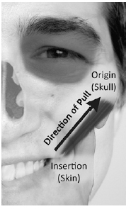
Figure 4.8 Markers placed along the zygomaticus major can measure the amount to which the muscle is flexed. This information can be used in post to drive a rig. (Image courtesy of Oleg Alexander.)
In a behavioral model information is typically lost. It is not only possible, but likely that the recorded performance will contain actions not present in the behavioral model. In the muscle space example, the effects of gravity, friction, or velocity would be lost whereas those elements are retained in a direct-drive method.
There are many different behavioral approaches to converting translations into facial animation. Some of the more common are muscle based and eigenfaces, but the most prevalent is FACS.
Facial Action Coding System
The Facial Action Coding System (FACS) was designed by Dr. Paul Ekman to give psychologists a common language when discussing facial expressions. The FACS process can encode all possible face motions into a set of 32 poses called action units (AUs). This means that, barring external influences, every possible facial expression can be broken down into some combination of these 32 poses. While Ekman accurately described 32 action units, he did not do so with computer animation in mind. It is therefore common to split some of the shapes into left and right. Additionally combination, in-between, and corrective poses are typical to counter artifacts from blend shapes and linear interpolations.
FACS is not limited to human faces. It can fully describe the movement of all kinds of faces, from cartoony to hyperreal. FACS action units and their meaning are so powerful they are studied by criminal psychologists, behavioral scientists, actors, animators, and riggers for their ability to describe human emotion in a quantifiable manner.
Before capturing an actor’s performance, it would be typical to perform a FACS session. A FACS session is a survey of the actor’s facial range of motion. In a FACS session an actor would perform some or all of the FACS poses in as isolated a manner as possible. This means that when performing any given FACS pose, that portion of the actor’s face would ideally be the only thing that moves. Performing a FACS session in this way allows for the pose to be more easily identified against a neutral pose.
Depending on the needs of the character and the production, the pre-capture survey may vary. In addition to neutral, full-open, and full-compressed, some commonly captured poses to inform rigging and animation are shown in Figures 4.9, 4.10, and 4.11.

Figure 4.9 FACS reference images. (Images courtesy of Oleg Alexander.)

Figure 4.10 More FACS reference images—eyes closed not illustrated. (Images courtesy of Oleg Alexander.)

Figure 4.11 Emotional expressions. (Images courtesy of Oleg Alexander.)
Cootes, T. F., Edwards, G. J., & Taylor, C. J. (1998). Active Appearance Models. European Conference on Computer Vision (pp. 484–498). Freiburg: Springer.
Felzenszwalb, P. F., & Huttenlocher, D. P (2003). Pictorial Structures for Object Recognition. International Journal of Computer Vision, 55–79.
Furukawa, Y., & Ponce, J. (2009). Dense 3D Motion Capture for Human Faces. International conference on computer vision and pattern recognition.
Hartley, R., & Zisserman, A. (2000). Multiple View Geometry in computer vision. Cambridge: Cambridge University Press.
Matthews, I., & Baker, S. (2004). Active Appearance Models Revisited. International Journal of Computer Vision, 135–164.
Torresani, L., Hertzmann, A., & Bregler, C. (2008). Nonrigid Structure-from-Motion: Estimating Shape and Motion with Hierarchical Priors. IEEE Transactions on Pattern Analysis and Machine Intelligence, 878–892.
REAL-TIME MOTION CAPTURE
John Root
Real-time motion capture refers to the capture, processing, and visualization of motion capture in a time frame that is, or appears to be, instant. Real-time MoCap is most commonly used as a tool to help actors get accustomed to their characters. Standing before a screen or monitor and being able to see yourself as a completely different person, creature, or thing is invaluable as an actor. Real-time MoCap can also be used for such things as director’s previsualization, camera layout, to animate live performances, or to immerse the person being motion captured into a virtual reality environment. However, because processing motion capture data is time-consuming and requires skilled technicians, real-time MoCap often involves strict limitations and compromises in quality. For this reason, it is common to separate real-time data from actual performance capture data.
Limitations
Real-time motion capture is an emerging field. It gets better every year. To date, however, significant compromises must be made to achieve real time. While some hardware providers are able to achieve remarkable real-time data, passive optical-based motion capture is inherently bad at real time.
Line of Sight
Optical motion capture is computer vision based and therefore the cameras must have an unobstructed view of the markers. In post, it is common for the tracking team to sort out glitches induced by cameras losing line of sight or markers having been occluded. Because real-time MoCap forgoes this post-processing, it is common to reduce the number of actors, limit the props, and govern the performance to maximize marker visibility. It would be a very hard, for instance, to generate real-time data for 13 actors rolling around on the floor.
Markers
Trying to make sense of the markers on the stage in real time is a daunting task. Beyond simply using fewer markers, inducing asymmetry into the marker placement will make them easier to identify. When the labeler is measuring the distance between markers, it is less likely to get confused and swap markers when the markers are placed asymmetrically. An asymmetrical marker placement, however, may be less than ideal for solving.
Solving
Some methods of solving are very processor intensive. As such they might not yet be possible in real time. Solving methods that are currently possible in real time often involve approximations and limitations that will yield a resulting solve that does not look as good as an offline solve. Given this, plus the compromises induced by marker placement modifications and performance alterations, what comes through in the real-time previsualization might not be indicative of the final quality of the animation.
Visualization
Real-time rendering technology is catching up with offline rendering technology at a radical pace. Some of the games on the shelves these days look nearly as good as the movies in the theatres. Using real-time game rendering technology to previs a film is becoming a common practice but one that requires significant investment. Off-the-shelf solutions including Autodesk’s Motion Builder offer a complete turnkey package to visualizing motion capture in real time. Expect that real-time-rendered characters and environments will come with compromises to visual quality, most notably in lighting and lookdev (look development).
Alternate Technologies
If real time is a requirement, passive optical technology might not be the best choice. Passive optical is known for its quality, not for its real-time ability. Some optical systems such as Giant and Motion Analysis are quite good at real time considering the limitations inherent in the technology. At the expense of quality, alternate technologies can deliver more reliable real time.
Active Optical
Active optical is similar to passive optical except that the markers are actually brightly lit LEDs. In an active marker system, the LEDs can be made to flash in a pattern that is recognizable by the cameras, thereby automatically identifying each marker for what it is measuring. In this manner the complex post-production process of labeling can be made obsolete and qualified data made available for the solver instantly.
Active optical systems suffer from significant limitations. They are limited to the number of markers they can track and limited also in that those markers are tethered to a battery pack. While the battery pack is small, light, and can be worn on the actor, this limitation makes capturing props and set decoration difficult.
Mechanical
Mechanical motion capture refers to motion capture that involves the technology itself being worn on the actor. With mechanical capture, a sensor of some sort is directly measuring a joint, limb, or object. Its information is transferred via a wireless or tethered connection and applied directly to a digital character. Often with mechanical capture, several technologies are combined into a more complete package. Potentiometers or bend resistors might be used to measure joint rotations while accelerometers could be used to measure limb velocity. While neither measuring technique is entirely accurate, when combined, they can produce very convincing animation.
Mechanical capture technology also enjoys several other benefits. Depending on the technology, a mechanical solution can be deployed under a costume or in a lighting environment not suitable for optical capture. Mechanical solutions often enjoy a significant range advantage over optical and do not suffer from occlusion.
The downside to mechanical solutions is that they commonly have little or no information about the global position of the capture subject. This means that while they can generate convincing joint rotations, the position of the character within the capture volume can be prone to error. By adding more technology, this limitation can be overcome. Other limitations of mechanical capture are mostly practical. The suits can be cumbersome and the sensors delicate.
1 Trackers and solvers: motion capture specialists who process data off the stage and turn it into useful animation.
2 Photogrammetry: process in which information is derived from a 2D image.
3 Volume: term that describe the motion capture stage. However, unlike “stage,” it implies a 3D space.
4 T pose: an action performed by the actor. It simply consists of standing with one’s feet straight down from one’s hips and arms out to the side, palms facing down. This pose is easy for the motion capture software to identify and label.
5 FACS: short for Facial Action Coding System, which is a method by which almost all possible facial motion can be encoded.
6 A centroid is the geometric center of a blob of pixels that are determined to be circular.
7 IK is short for Inverse Kinematics. It most commonly refers to the solving of a chain of joints to reach a known destination. (Example: Moving the hand on a 3D model moves the rest of the arm and elbow correctly.)
8 Discussed in more detail in the Facial Capture section.
9 The epipolar geometry of two cameras defines the possible locations of a point seen in one camera in the other camera. For an ideal pinhole camera, a point seen in one camera exists along a line in another camera.
10 The chances of this happening can be mitigated somewhat by capturing a reference session of each actor with a higher marker count. A statistical model can then be used to predict the position of the extra markers from the markers captured during the shoot. This is often referred to as gap filling.