
3
ACQUISITION/SHOOTING
WORKING ON SET
Scott Squires
A small group of the visual effects team works on set during the production to make sure that all of the shots that will require visual effects are shot correctly and to obtain the necessary data and references.
The visual effects crew can consist of the following:
• The VFX Supervisor or plate supervisor works with the director and key production departments to make sure visual effects shots are correct creatively and technically.
• An animation supervisor may be on set if there is a lot of complex animation to be added.
• A VFX Producer may be on set to help organize and schedule the visual effects crew and to flag issues that may affect the budget.
• A coordinator takes notes, logs visual effects shots, helps to communicate with the different departments, and can fill in for the VFX Producer.
• Other visual effects production personnel handle the reference items (chrome sphere, monster sticks1, etc.), take reference photos, and handle other miscellaneous reference gathering.
• Data collectors (sometimes called data wranglers or match-movers; the terms vary from company to company) document all camera and lens information and take measurements of the set.
It is not unusual for members of this crew to fill multiple positions, and on a small show this may all be handled by the VFX Supervisor. Additional visual effects personnel may come to the set for short durations, such as modelers to help scan and photograph the actors, sets, and props for later modeling. Shooting can be a single day for small projects or up to 6 months or longer for a large film.
Working on the set is much different from working at a visual effects facility. It tends to alternate between boredom and terror—waiting for the crew to get to the visual effects shot(s) and rushing around to actually film the shot (sometimes under adverse conditions). There can be a lot of pressure on the set due to the time limits of getting everything shot and the costs of shooting. Depending on the show, the visual effects crew may be involved in just one shot that day or may be required to work on every shot. Being on a set and observing are very good experiences for any visual effects artist. It will do a lot to explain why visual effects plates are not always perfect.
Shooting may take place on a sound stage or outside for exterior shots. A live-action shooting day is usually 12 hours long. Locations may require a good deal of climbing or walking, so physical fitness is called for. Exterior shooting will require standing outside from sunrise to sunset in sun, rain (natural or made by the special effects team), cold, or snow. Night scenes require working from sunset to sunrise. Dress appropriately for the given weather—good walking shoes, socks, hat, layered clothing, sunscreen, sunglasses, or full rain gear (including rain pants) for rain and very heavy boots for cold weather. Have a small flashlight. Think of it as camping with 100 to 200 other people.
The visual effects crew will have to work hand in hand with the other departments, so it is important to keep a good relationship with them. (See Chapter 2 for a discussion of the basic departments.)
Typical Process
Call sheets are handed out the night before. These list the scenes to be shot the next day and include the actors and crew members to be on the set and their call times (time to arrive on set). They will also note any special instructions for transportation or shooting that day.
The Director will arrive and meet with the 1st Assistant Director (1st AD) and Director of Photography (DP) to discuss the order of the day and the first shot. The VFX Supervisor should be involved in this to help plan the visual effects needs. Sometimes this is done at the end of a shooting day to prepare for the next day.
The Director works with the actors to block out a scene with the 1st Assistant Director and Director of Photography. If the blocking of the scene has a large impact on the visual effects (e.g., an animated character is to be added), the VFX Supervisor should be involved as well. A stand-in or creature reference may be required to block2 the scene. The VFX Supervisor should have a reduced set of storyboards (to fit in a coat pocket) to refer to. It is best to supply these to the DP and Director as well. A laptop with a DVD or video file of the previs is also useful to play back for the Director and actors to get a sense of the scene. A handheld device (iPod, iPhone, etc.) can also be useful for referencing previs material on set.
The Director of Photography and VFX Supervisor may discuss camera placement as it relates to visual effects. A model or other visual reference may be placed in front of the camera to help determine final framing. If the shot is to be matched to another element already shot, such as a background plate, then that should be referenced with the DP as well so that the lighting and angle can be matched. The DP works with the gaffer (head of the electrical department) to set the lighting and with the camera operator to set up the camera equipment and the camera move required. This may take a few minutes or several hours, depending on the complexity of the scene.
The VFX Supervisor should discuss the shot and requirements with the visual effects crew ahead of time. This will enable them to set up any special equipment (i.e., transit,3 witness cameras,4 etc.) so that they are prepared. Any tracking markers or other visual aids should be set up as soon as possible so that this doesn’t slow down the current setup, the crew, or the progress of the director’s day. Any measurements that won’t change (such as a building or street) should be done as soon as is feasible. The visual effects crew has to work as efficiently as possible as a team to make sure everything gets done. On a large show there may be an office for visual effects near the stages and a trailer for location work. The equipment is usually stored in these areas and moved to the location by modified carts to handle rough terrain. Production should provide the visual effects crew with production walkie-talkies to keep in communication. A channel is usually assigned to each department.
Once the shot is ready, the visual effects references may be shot at the start or end of the sequence of takes. Someone from the visual effects crew holds up the gray sphere, chrome sphere, or other references while the camera rolls. (See On-Set Data Acquisition in this chapter for details.) It is common practice to add a “V” to the slate to indicate it is a visual effects shot. All of this should be discussed with the production department (1st AD, script supervisor, etc.) before production begins because they may require different slating regimens.
An actor may be given an eye-line reference for anything that will be added later (e.g., the window of a building, a CG creature). This will help the actor look at the correct place even if the object will be added later in post-production. A reference take may also be shot of an actor standing in for a CG creature, or a monster stick may also be used for a large creature to be added. This provides the actors with an eye-line and timing reference. It helps the director to visualize the shot, and it helps the operator to know what the action is. It is also useful in post-production for the animators to see the action and timing.
The Director, Director of Photography, and VFX Supervisor usually gather at the video village to watch the shot. Video village is the name given to the sitting area where the video monitor (or multiple monitors) is set up. The video assist operator handles this. The video comes from a video tap (camera) on a film camera or may be from a digital camera. Each take is recorded for referencing by the Director for performance. Normally, directors’ chairs are assigned to all key personnel at the video village. For a show that is heavy with visual effects, this should include the VFX Supervisor to make sure the video is always visible to them.
The VFX Supervisor watches each performance carefully and monitors a number of things, including the eye lines of the actors and extras, any crossing of the matte lines, the locations of the actors, and the timing of the special effects, camera move, and actors. The VFX Supervisor has to keep in mind where the creature or any additional objects will be added and their timing relative to what the actor does. It is also necessary to keep an eye on things that should not be in the shot (microphone, crew member, tattoos on the actor, etc.). If there are issues regarding the actors, the VFX Supervisor should discuss these with the Director, who in turn will discuss them with the actors. The VFX Supervisor should avoid giving direction to the actors to avoid confusion. Other issues may be flagged to the 1st Assistant Director or the DP, depending on the specifics.
The VFX Supervisor has to weigh the cost and time to make an adjustment on the set against fixing the problem or making the change in post-production. In some cases it will be less expensive and faster to make the adjustment in post, but if it is critical, the VFX Supervisors will have to stand their ground to make sure the shot is done correctly. Complaining about it months later in post will not be of any value. Any issues that will have a large cost impact should be flagged to the VFX Producer (or, if unavailable, the film producer).
After each take someone from the visual effects crew records information from the camera assistant with regard to camera settings (lens, tilt angle, f-stop, focus, etc.) for the start and end of the camera move. Multiple cameras may be used that will need to be monitored and recorded. Some camera views may not require visual effects. In some cases a splinter unit will take another camera and shoot a totally separate shot at the same time off to the side. It is necessary to monitor that camera as well if it is being used for visual effects shots.
This process repeats itself throughout the day. Lunch is provided and craft services sets out snacks during shooting. Restrooms on location are at the honeywagon (a truck with built-in restrooms for the crew).
The crew filming the key live action with principal actors is considered the 1st unit (or main unit). On large productions a 2nd unit may be filming different scenes on different sets or locations, such as inserts, scenes with secondary actors, or action scenes that production has determined will be more efficient to shoot with a separate crew. If these scenes require visual effects and are being shot the same day as the 1st unit shooting, then another VFX Supervisor and visual effects crew will be required for this unit.
Guidelines for On-Set Work
• Be professional in actions, with words, and when working with others.
• Be quick and efficient at the tasks you have been assigned. Avoid holding up or slowing down the production any more than is absolutely necessary.
• Be quiet when the camera is rolling.
• Do not enter a stage when the red light outside the door is flashing.
• Avoid being in the shot. There may be a number of cameras shooting, with very large camera moves. Check to see where the cameras are set and how much they will cover during the shot. Ask the supervisor and check the video if necessary.
• Avoid getting in the actor’s eye line. The actor will be focused and looking at another actor or looking off the set at something or someone who is supposed to be off-screen. Any movement where they are looking will be distracting and cause them to lose focus.
• Do not move, touch, or borrow items controlled by other departments (C-stand, light, etc.). Ask someone from the appropriate department for permission to do so.
• If you need to add markers to an actor’s wardrobe, talk to the head of the wardrobe department. Check with the 1st AD first since this may affect other cameras, including non-visual effects shots.
• If you need to add markers to an actor, talk to the makeup person. Check with the 1st AD since this will affect other cameras, including non-visual effects shots.
• Prepare and gather data ahead of time when possible. Measure the sets, gather blueprints, set bluescreen markers, etc. Construct reference objects and transportation carts before production begins.
• Take care of the visual effects equipment. All equipment should be protected from the elements (plastic covers for transits, protective bag for the chrome sphere, etc.). All equipment should be locked up or watched by a crew member or security guard when not in use. Losing or damaging a critical and expensive piece of equipment on set will be a real problem. In cold weather watch for condensation on equipment.
• Always carry a small notebook and pen for notes.
• Monitor the areas you are covering and adjust accordingly (camera move changed, another camera added, etc.).
• Be alert. The shot could be changed significantly between takes, or plans may be changed without much notice. Be ready for a call from the VFX Supervisor.
• If anything is preventing the visual effects task from being completed (obtaining camera data, taking measurements, etc.), it should be flagged to the VFX Supervisor immediately. The VFX Supervisor may need to hold production for a moment to obtain the necessary element or reference data.
• If there is a visual effects question or any confusion regarding the requirements, check with the VFX Supervisor immediately.
• If the only time to take texture photographs or measurements is during lunch, check with the VFX Supervisor or VFX Producer, who will in turn discuss it with the 1st AD and the DP. Lights may have to be left on, and all crew members must be given their full lunchtime.
• If you are leaving the set for any reason, notify the VFX Supervisor before you leave.
• Avoid hanging out at the video village if you do not need to be there.
• Always be on the set on time as per the call sheet.
• If actors need to be scheduled for scanning, check with the VFX Supervisor so they can work with the 1st AD.
• Keep an eye on production. It’s not unusual for them to try to shoot a visual effects shot without supervision (if the VFX Supervisor is unavailable). This is always problematic.
• Be alert to safety issues on the set and location. There can be cables, equipment, and moving vehicles that need to be avoided. The temporary and constantly changing nature of the environment can lead to trouble if a crew member is not paying attention.
COMMON TYPES OF SPECIAL EFFECTS
Gene Rizzardi
What Are Special Effects?
Special effects are the on-set mechanical and in-camera optical effects, which are created in front of the camera—also referred to as SFX. Special effects include, but are not limited to, pyrotechnics, specially rigged props and cars, breakaway doors or walls, on-set models and miniatures, makeup effects, and atmospheric effects such as wind, rain, snow, fire, and smoke.
A Brief History of Special Effects
The quest to suspend reality has been the challenge of special effects since the beginning of film history. Special Effects progressed from simple in-camera tricks at the turn of the century to increasingly complicated works of the ‘60s, ‘70s and ‘80s (when special effects miniatures and optical printers were the norm) to the complex and seamless effects of today (digital cameras, CGI, digital pipelines, and digitally projected films). Special Effects still plays an important role today as a cost-effective means of creating reality and by helping the filmmaker create his vision.
The Special Effects Supervisor
As the digital and physical worlds merge in film and television, the work of the SFX Supervisor and VFX Supervisor must also change to accommodate the demands of the project. Cooperation between these two individuals is of the utmost importance to create seamless and convincing visual effects. Understanding and communicating the components of each visual effects shot is critical for the successful completion of the effect. This begins in pre-production, when the VFX Supervisor and SFX Supervisor determine what techniques and which shots will use a blend of visual and special effects. Storyboards and previs are quite helpful in this process. Some shots may be all visual effects with special effects providing only a separately photographed element to be composited later. Others might be more special effects with visual effects enhancing them or providing rig removal.
Working with the Visual Effects
In many instances the SFX Supervisor’s skills will complement those of the VFX Supervisor to create or complete the action of a shot:
• Elements: The SFX Supervisor can provide flame, smoke, water, pyrotechnics, dust, snow, and other elements as raw material to composite into the shot.
• Greenscreen: The SFX Supervisor can work with the VFX Supervisor and the DP to position and move actors and/or props to provide direct active elements for compositing.
• Interactivity: The SFX Supervisor can provide interactivity during principal photography or 2nd unit shots to complement digital or composited elements.
Visual Effects in Service to SFX
Visual effects can be most useful to the needs of special effects by performing the following:
• Rig removal, such as removing cables, support arms, or safety equipment from the shot.
• Face replacements, which allow stunt performers to stand in for principal actors.
• Effect enhancement, such as adding more flame, rain, water, dust, smoke, or other elements to the shot.
• Compositing, where logistically complicated and expensive shots can be shot as elements by a visual effects, special effects, and stunt unit and composited into plates shot at a principal location.
In the end, seamless, realistic, and cost-effective visual effects are the result of careful planning involving visual effects, special effects, stunts, miniatures, and the art department to ultimately realize the director’s vision.
Special Effects Design and Planning
It all starts with the script. The experienced SFX Supervisor will break down the script by the various effects and elements required. Once a list of atmospheric and physical elements is created, discussions about the budget and schedule can begin. This process may go through many versions before it is completed. It is a valuable period of discovery before the construction begins and the cameras roll.
Storyboards and Previs
Storyboards tell a visual story of the film. They give the key elements in the scene for the Director and Production Designer to plan the film action, construction, and scheduling. This visual reference is also a valuable tool for the SFX Supervisor, who can use it to visualize the plan of action, such as where the atmospheric effects are needed and where the mechanical, pyrotechnic, or physical effects are needed, in order to plan and achieve the desired shot(s). This valuable tool, along with a location and technical scout, will give the SFX Supervisor invaluable information on how to achieve production goals.
The Elements: Rain, Wind, and Snow and Ice
Rain
The ability to make rain indoors or outdoors is part of the movie magic that adds convincing realism to any movie. Rain bars 60 and 100 feet long with specially designed sprinkler heads can cover wide areas, but the most important part of rain making is to place the rain above the actors using the “over-the-camera” effect.
• By adjusting the water pressure, rain can be made to appear as a fine mist (high pressure) or heavy droplets (low pressure).
• Backlighting rain will make it more visible; frontlighting it will make it almost disappear.
• To make rain appear to be falling straight down, one must move the rain bars or rain towers to a higher position to eliminate the effect of crossing rain.
• Rain rigs can be used with traveling cars to extend the effect from the driver’s point of view.
• Rain windows are devices that create reflections for lighting effects to simulate rain.
• Indoor or outdoor sets can be rigged with rain bars to make rain appear to be falling outside a window. Rain mats or hog hair can control the noise made by the rain falling in the drip pans.
Wind Effects
Wind is another effect an SFX Supervisor can use, creating anything from the soft rustling of the leaves on the foliage outside a set window to raging tornadoes. The devices used range from small electric fans to large electric or gas-powered machines that can move air at over 100 mph.
• E-fans are a staple of any special effects kit. Their use varies from the soft blowing of leaves to moving smoke on set to add atmosphere. The E-fan is well suited to this work because its flow is very directional.
• Ritter fans are large electric fans that can be placed on gimbals or platforms and are capable of moving air in excess of 100 mph. They can be fitted with rain bars to make driving rain for raging storms.
• Jet-powered fans are used for tornado effects, large dust clouds, and destructive winds. They also emit a lot of heat, so great care must be used when they are working.
Snow and Ice
Snow and ice can be made from real ice for the foreground areas or where actors may want to interact with it and get a wet effect. Snow is usually made from paper products since this does not melt, and if applied properly, it is easy to clean up. Paper snow is also good for extended snow scenes because ice would melt after the first day and make everything wet and muddy.
• Effective snow scenes must be planned properly. Failure to apply snow in an orderly process will make for an extended and messy cleanup.
• A white underlay will create a good surface that will protect the ground or surface below. The underlay will also give you a white base to apply the snow on. Snow will then be sprayed over this underlay to achieve the desired effect. The snow can be made to appear deeper or undulating by placing sandbags or bales of hay beneath the underlay before the snow is sprayed.
• Falling snow, water dripping from icicles, and frost on windows are routinely created by the SFX Supervisor.
• Frosty breath can be created in a refrigerated set or with cigarette smoke and will be more convincing and cost effective than CGI replacements.
• Frozen pond or lake surfaces can be created with heated paraffin wax that is carefully flowed onto the surface.
The SFX Supervisor will work with the VFX Supervisor, Director, and location manager to get the right snow look for the scene. Permits are required to make snow in state or federal parks, and cleanup procedures must be strictly followed so as to not endanger the local plant and wildlife.
Smoke, Fire, and Pyrotechnics
Pyrotechnics covers a wide and impressive range of effects, from simple sparks and smoke to squibs used for bullet hits to the fiery destruction of whole city blocks.
Pyrotechnic special effects are generally designed to produce a great visual and audio effect without the massive destruction associated with commercial blasting and military explosives. Filming these types of explosions is difficult at best: Safety concerns prevent filming in close proximity, and explosions happen too quickly for effective filming. The special effects pyrotechnic explosions enable more effective filming, allowing stunt players to be relatively close. The film crew can be close enough to shoot it, and the explosion itself is slow enough to be captured on film as a progression of events, with fire and smoke, while anything that may fly off and injure someone is safely tied with cable. Every aspect of the pyrotechnic is designed to create a great and breathtaking visual.
All pyrotechnic effects must be performed with constant consideration for safety, because all pyrotechnic materials can cause harm. These materials, and the pyrotechnic operator as well, are tightly regulated by a host of government agencies, starting with the Bureau of Alcohol, Tobacco, Firearms and Explosives (BATF&E) and extending down to local jurisdictions, usually the local fire department. Each use must be licensed and permitted by these agencies.
A few examples of the wide range of pyrotechnics (and this just scratches the surface) are as follows:
• Pyrotechnic smoke: This includes colored smokes, smoke that can be set off at a distance, or smoke in conjunction with explosions or fire.
• Squibs: Squibs are small electrically detonated explosive devices used for bullet hits on props, buildings, water, and cars. Squibs are used inside special shields in conjunction with small bags of movie blood on actors and stunt performers to create horrifying body hits. There are even tiny 1:32 size squibs for use with makeup effects to attach onto prostheses for close-up effects. Squibs are used to operate quick releases, trunnion guns,5 and glass poppers. Squibs are also used to initiate detonating of primer cord6 and black powder lifters.
• Spark effects: A wide range of spark effects are available, from the tiny Z-16 squib to giant Omnis that can fill a room. In addition, there is an entire range of stage-specialized spark effects that come in colors and have a set duration, spray, or fall.
• Display fireworks: Public display-type fireworks are occasionally used by special effects teams. These include all manner of aerials and set pieces.
• Specialized effects rockets: These will send a rocket down a wire and produce flame and smoke. These devices fit in the mouth of a cannon barrel and mimic the firing of the cannon. Custom pyrotechnics can also be designed for specific gags.
• Explosions: A staple of special effects, these include car explosions, where the car blows up and flies through the air; blowing up of buildings; and huge dust explosions far away to simulate artillery fire. Explosions can be created with or without flame and with stunt performers in or very close to them.
• Car effects: Rollover cannons for stunt-driven picture cars7 are frequently operated by pyrotechnics. Car crashes, explosions, and fires are some of the many car effects that are written into today’s scripts.
• Miniature pyrotechnics: This is an entire specialized art in itself. The pyrotechnics must match the miniature in scale, and the timing is frequently measured in milliseconds due to high-speed photography.
• Fire effects: Burning houses, fireplaces, bonfires, candles, campfires, burning bushes, lightning strikes, and many other fire effects are the responsibility of the SFX Supervisor.
All special effects equipment can cause serious injury when used improperly. Hire a trained professional to use such equipment.
Mechanical Effects
Mechanical effects are an integral part of the special effects department’s responsibility and cover a wide range of rigging, building action props, creating specialized elemental effects, and providing mechanical help for other departments. Examples include the following:
• Action props: props that do something on set, such as mechanical bulls, clock workings, gadgets with blinking lights, retractable knives, trees that fall on cue, or self-growing plants. These may include all manner of working mechanisms, either built from scratch or existing items modified to work on set in a film-friendly manner.
• Breakaways: balsa furniture, windows, walls, door panels, hand props, floors, glass of all sorts, concrete, or handrails.
• Crashing cars: roll cages to protect stunt performers, rollover cannons, cars with self-contained traveling flames and other effects, cables pulling cars in stunts too dangerous for even stunt drivers to perform, on-cue tire blowouts, special picture cars, cars ratcheted or launched by pneumatic cannon through the air. Other requirements may include wheels that come off, cars breaking in half, or cars that appear to drive backward at high speed.
• Bullet hits and blood effects: on walls, cars, people, water, plants, concrete, or windows. Bullet hits can be sparks or dust puffs or, for hits on wardrobe, can spew blood. Other blood effects are blood running down the walls, blood sprayed on the walls, or props that bleed—red blood, clear vampire slime, or green goo—as well as pipes that burst and gush blood, slime, and goo.
• Action set pieces: sets on gimbals, elevator doors and elevators themselves, trapdoors, guillotine doors, tilting floors, water tanks, floods, avalanches, collapsing buildings.
• Set rigging: fireplaces, showers, tubs, stoves, heating swimming pools or any water that crew and actors have to work in, or moving on-stage greenery with monofilament or wire to simulate wind.
• Flying effects: flying and moving people and objects on cable, synthetic rope, wire cranes, parallelogram rigs, hydraulic gimbals and overhead, floor, subfloor, and through-the-wall tracks, or arrows and rockets on wires.
• Greenscreen work: rigging actors, props, and models to fly in front of the green screen. With today’s digital wire removal, this job has become much easier and safer than in days past when actors were flown on fine music wire that was more likely to break than the thicker, safer wires of today.
• Set effects: stoves, kitchen sets, and working faucets, showers, or bathrooms.
Flying Wire Rigs and Stunts
Wire flying is one of the oldest forms of illusion. Several basic systems are used in the creation of flying effects as well as countless variations of them based on the requirements of the job and the SFX Supervisor’s imagination.
Flying rigs are either controlled by overhead track systems or, in certain instances, by cranes used to hold the flying rigs.
• Overhead track system: This system can be set up to fly a person or object in either a two-direction system, where the actor or object moves either left to right or front to back on stage at a fixed height, or a four-direction system, which allows the actor or object to move left to right and up and down at the same time. A third variation involves an overhead cab that contains a special effects technician who operates a device that allows the actor or object to spin.
• Pendulum or Peter Pan rig: This is the most complicated flying device to rig and work because it demands a comprehensive rehearsal and coordination between the actor and the effects person to make the actor fly on stage and land in an exact location.
• Cable overhead flying rigs: These are similar to the overhead track system and can also be used outdoors, with the traveler mounted on an overhead cable system that may span 1000 feet or more. They can have all the same features as the overhead track system. An example of this is the camera systems used in football and soccer that follow the actors down the field, or when the shot involves a character like Spider-Man who travels along the street by leaps and bounds. CGI and greenscreen effects can be used in conjunction with this rig to place an actor or character anywhere the director imagines.
• Levitation: As opposed to flying, this method of flying actors or objects uses lifting mechanisms such as parallelograms or vertical traveling lifts. The device can be as simple as a fork-lift or as complex as a counterweighted lift machine. Although typically stationary, it can be mounted on a track to give a left-to-right motion. It also can be used with miniatures.
• Descenders: These are used to control the fall of a stuntperson who leaps from a tall building or cliff when the terminal velocity can exceed the ability of the airbag safety system or when an actor needs to stop inches from the floor, as in Mission: Impossible (1996).
Flying effects and stunts involving actors are the shared responsibility of the SFX Supervisor and the Stunt Coordinator. They work as a team to provide the proper rigging and equipment to achieve a safe and desired result that is repeatable.
Safety
The most important aspect of special effects is ensuring that all effects and rigs are executed in a manner that maximizes safety and minimizes risk. This is a tall task in that many effects are designed to produce the appearance of great danger, with the cast and crew close enough to film, but must at the same time protect them from harm. The SFX Supervisor must not only operate all effects safely but must also take precautions for the unnoticed hazards of special effects:
• noise,
• tripping and slipping,
• dust,
• smoke,
• moving machinery,
• flammables,
• high-pressure gases and liquids,
• toxic substances, and
• wind effects and flying debris.
Careful planning goes into each effect or gag, including consultation with the stunt coordinator, the 1st AD, the VFX Supervisor, and anyone else concerned. If pyrotechnics or fire is involved, the fire department having jurisdiction must issue a permit. Immediately prior to the filming of the special effect, the 1st AD will call a safety meeting, where it is ensured that everyone knows what to do and all contingencies are addressed.
The VFX Supervisor can frequently help out with safety by providing rig removal for safety devices, by adding or enhancing elements to increase the feeling of jeopardy, and by compositing actors and stunt performers into shots in which their physical presence would expose them to too much risk.
When working on set, it is important to be aware of your surroundings, pay attention, and work safely. Look out for your coworkers and keep your eyes open for anything that could be a potential hazard. If you have a doubt, ask the proper personnel to have a look at the condition you are concerned about. Safety is everyone’s responsibility.
FRONT AND REAR PROJECTION SYSTEMS FOR VISUAL EFFECTS
Bill Mesa and John Coats
In the pre-digital era of visual effects, front projection, rear-screen projection, and “side-screen” projection were processes used for creating large-scale sets and new environments as well as for moving images out the windows of cars and planes. Although the techniques for using these tools have changed a great deal, the mechanics of the tools are basically the same, except for the new digital projection systems. In the past the background plates had to be created prior to on-set shooting, and once the on-set shooting was done, there was no fixing it in post, but it did and still does allow one to shoot many versions of the action with the subjects to give the director a variety of takes from which to choose. Experimentation can be done on the set with lighting and other smoke and debris elements to blend the subjects together. A good example of this is a shot from The Fugitive (1993), in which dust and debris shot from an air cannon landed on top of Harrison Ford just as a train crashed into the hillside. This was done using a front projection system that tied in all of the dust and debris on top of Harrison with the plate for integration of the elements.
Rear Projection
Advantages
Rear projection holds fine edge detail because no mattes are involved, since the background and the object in front of the screen are being shot as one. The object or person in front of the screen acts as an interactive light source because the two objects are together. One obstacle to overcome when backlighting a person or object is to make sure the bounce light from that person doesn’t contaminate the screen and cause a loss of black detail or make the image look low in contrast. Adding black velvet to the back of the person to cut down on the spill light works well for this issue, as long as the person isn’t rotating. The more the ambient light spill can be blocked, the better the results.
Rear projection can be cost effective, especially when there are similar shots that just require a change of backgrounds—allowing many shots to be done at one time or a whole scene to be played out from that angle. Since the shots are finished on stage, no post-production costs are associated with rear projection and results can be seen immediately—thus providing the ability to make eye-line, position, and other corrections in real time.
Disadvantages
Heavy expenses can be involved if large screens are used, which would require a move-in day, a setup and test day for testing background plate colors, plus however many actual shoot days, and then a wrap day. They also require a large space. For a shot out the front window of a car, an 18-foot screen is required—with little to no camera movement. Additionally, 50 to 60 feet of space would be required behind the screen for the projector. That is a lot of space. Getting high-resolution images for backgrounds requires shooting in VistaVision or using a high-resolution digital system. Even then it is difficult to get black detail. It also requires all of the backgrounds to be registered and color-corrected plates to be made prior to filming on stage. In many of today’s big visual effects movies, it is impossible to generate backgrounds with all the necessary elements. Shooting this way can be limiting because the background timings can’t be changed in post.
Front Projection (Blue or Green Screens and Picture Imagery)
Advantages
There are still good reasons to use blue or green screens. The Poseidon Adventure (2006) had an all-stainless steel kitchen. Some tests were shot using traditional blue screens, but the blue contamination was so great that it couldn’t be removed. Using a front projection blue screen eliminated the blue reflection because the screen doesn’t put out any blue light. One light source can light up a 20- by 40-foot screen with an even light field. This can provide much higher light intensity for working at higher f-stops. It is easy to change out blue or green screens for whatever color is needed. The space needed is a lot smaller than with rear projection. Although front projection with picture imagery is not used much anymore due to the quality of the final image, it could be used when a scene has many of the same shots or shots that go on for long periods of time.
Disadvantages
The screen material is quite expensive and must be kept in optimum condition for continued use. It requires a special camera projector or light source setup.
If the alignment of the camera projector is not 100% correct, fringing may appear around the actors. This requires setup time to get the projector and camera lined up, depending on how close or far away the actor is from the camera. There are also issues with haloing, depending on how dark the projected image is and how much light is on the actor or foreground object. Again, haloing can be reduced by putting black velvet on the actor’s backside, as long as the actor doesn’t rotate during the shot.
Rear Projection Equipment
Digital DLP and LCD Projectors
Considerations in using digital projectors are the limitation of resolution, contrast ratio, and the light output of the projectors. The size of the projected image needs to be known before determining the required projector light output. Also, different screens react differently to the camera being off center. There are 50/50 screens that allow camera moves of up to 50% off center. These screens need higher light output from the projectors. There are also synchronization issues, depending on what type of projector is used—especially when shooting with 24-frame cameras. This must be tested prior to shooting. Sometimes flickering will occur. It is always good practice to start with the best quality image possible and then diffuse or soften on the set. Special equipment might be needed for soundproofing the projector system.
Film Projectors
These can give greater light output but require registered film plates.
Front Projection Equipment
Characteristics of the Retroreflective Material
The material needs to be mounted in a pattern that will not show up when an image is projected on it. Hexagonal and diamond patterns have been used successfully. On small screens, the straight 3-foot widths with back-beveled cut edges to allow seamless overlap have been used successfully. This needs to be done in completely clean conditions, with white gloves and no oil.
Set Lighting Conditions
Although small projection systems on cranes have been used, they need to stay parallel to the screen axis or the image will start to fade. In the lighting setup of the actors or objects, all lights need to be blocked from hitting the screen or they will gray the image.
Camera-Mounted Light Source
Various light sources, including LED (light-emitting diode) rings, can be placed around the camera lens to light up (with a blue or green source of light) a screen. If using a projector source, this requires a beamsplitter, generally 50/50 in transparency, with antireflection coatings. If there is any camera movement, the projector and beamsplitters must all move together and stay parallel to the screen.
Large-Area Emissive Displays (LCD, Plasma, and Jumbotron Screens)
These types of screens are often used just to reflect imagery on windows or reflective objects, but they can also be used as backgrounds in place of rear projection. As these screens continue to get better due to their great light output, they will take over the projection systems for smaller backgrounds. Because of their high output and low contamination threshold, the Jumbotron and others can provide some great flexibility for various uses. Have fun trying all the new technology.
GREENSCREEN AND BLUESCREEN PHOTOGRAPHY
Bill Taylor, ASC
Overview
Greenscreen and bluescreen composites begin with foreground action photographed against a plain backing of a single primary color. In a digital post-production process, the foreground action is combined with a new background. The new background can be live action, digital or traditional models, artwork or animation, or any combination.
For the sake of simplicity, we’ll refer to “greenscreen” shots, with the understanding that the screen or backing can instead be blue or even red.
These composites (and others using related technology) are also called traveling matte shots because they depend on creating an alpha-channel silhouette “mask” or matte image of the foreground action that changes and travels within the frame.
The final composite is usually created in post-production, although real-time, full-resolution on-set compositing8 is possible in HD video.
Function of the Backing—Green, Blue, or Red
The purpose of the blue or green backing is to provide an unambiguous means by which software can distinguish between the color hues and values in the foreground and the monochromatic backing. White and black backgrounds are used in special circumstances to create luminance masks or “luma keys,” but since it is likely that similar luminance values will be found in the foreground, these backings have limited use.
The degree to which the compositing software “sees” the backing determines the degree of transparency of the foreground in the final composite. Where the backing value is zero, the foreground is completely opaque; where the backing value is 50%, the foreground will be partly transparent, and so forth for all values to 100%, the areas of the frame where the foreground image is either not present or completely transparent. The goal is to retain the foreground subjects’ edge transitions (including motion blur), color, and transparency in the final composite.
Fabric and Paint
The best materials currently available are the result of years of research to optimize lamp phosphors, fabric dyes, and paint for film purposes.
Fabrics
When using fabric backings, minimize the seams and avoid folds. Stretch the fabric to minimize wrinkles.
Even an indifferent backing can give good results if it is lit evenly with narrowband tubes to the proper level (within plus-or-minus 1/3 f-stop). Spill from set lighting remains a concern.
Composite Components Co.9 offers a fabric that is highly efficient, very light, stretchy, and easy to hang. It must be backed by opaque material when there is light behind it. The green fabric is fluorescent, so it is even more efficient under UV-rich sources like skylight. CCC also makes a darker material for use in direct sunlight.
Following Composite Components’ lead, many suppliers now provide “digital-type” backings of similar colors. Although similar in appearance, some of these materials are substantially less efficient, which can have a great cost impact when lighting large screens. Dazian Tempo fabric, a fuzzy, stretchy material, has a low green or blue saturation when lit with white light, so it isn’t recommended for that application. Dazian’s Lakota Green Matte material is a better choice for white-light applications like floor coverings; it is resistant to fading and creasing and can be laundered.
Paint
Composite Components’ Digital Green or Digital Blue paint is the preferred choice for large painted backings. As with fabrics, there are other paint brands with similar names that may not have the same efficiency. Paints intended for video use, such as Ultimatte Chroma Key paints, can also be used with good illuminators (lights). A test of a small swatch is worthwhile for materials whose performance is unknown.
Backing Uniformity and Screen Correction
Since the luminance level and saturation of the backing determine the level of the background scene, it is important to light the backing as uniformly as is practical, ideally within plus-or-minus 1/3 f-stop.
Although a perfectly uniform backing is desirable, it may not be achievable in the real world. (Please refer to the Illuminators section in this chapter.) If the backing itself is blotchy, the background image will become equally blotchy in the composite.
It is possible to clean up the alpha channel by increasing the contrast (gamma) in the blotchy areas until all the nonuniform values are pushed (clipped) to 1.0. Although clipping the alpha values eliminates the nonuniformity in the backing, the same values on the subject’s silhouette are clipped too, resulting in the subject’s edges becoming hard and shadows and transparencies starting to disappear.

Figure 3.1 Alpha clipping. (Image courtesy of Ultimatte Corporation.)
In Figure 3.1, frame A shows the actor shot against an uneven blue screen. Frame B shows the alpha “cleaned up” by boosting the contrast. Note that fine detail in the transparent shawl and the hair has been lost in the alpha and in the composite, frame C.
Virtual shooting sets are even more troublesome. They often contain green set pieces that correspond to objects in the final background so that the actor can climb stairs, lean against a doorway, and so forth. The props all cast shadows on themselves and the green floor, and the actor casts shadows on everything. With lighting alone it’s impossible to eliminate set piece shadows without washing out the actor’s shadow.
Several software packages have features to cope with nonuniform backings. Ultimatte Screen Correction software can compensate for backing luminance variations as great as two stops.
Screen correction is easy to use: After lighting the set, shoot a few seconds before the actors enter. This footage is called the clean plate or reference plate. All the backing and lighting imperfections are recorded on those few frames. Now shoot the actors as usual.
In the composite, the artist selects a well-lit reference point near the subject. Software derives a correction value by comparison with the clean plate and corrects the rest of the backing to the measured level. Software compares the clean frames pixel by pixel with the action frames and inhibits the correction process in the subject area (the actor) and proportionately inhibits the correction in transparencies. In the example shown in Figure 3.2, frame D shows the clean plate without the actor. The backing has a wide variation in color and brightness, simulating a virtual set. Frame E shows the alpha with screen correction. Note that the fine hair detail and the full range of transparencies in the shawl have been retained in the alpha and in the composite, frame F. This demonstration frame is an extreme example; very dark and desaturated backing colors such as those at the right and top right should be avoided in the real world!

Figure 3.2 Screen correction before and after. (Image courtesy of Ultimatte Corporation.)
Backing defects, scuffed floors, set piece shadows, uneven illumination, and color variations in the backing and lens vignetting all disappear. The actors’ shadows reproduce normally, even where they cross shadows already on the backing.
There is a significant limitation: If the camera moves during the shot, the identical camera move must be photographed on the empty set for the length of the scene. Although it is reasonably quick and simple to repeat pan-tilt-focus camera moves with small, portable motion control equipment, skilled matchmovers can bring a “wild” clean pass into useful conformance around the actor and remove discrepancies with rotoscoping. Some match-movers prefer the clean footage to be shot at a slower tempo to improve the chances that more wild frames will closely match the takes with the actors.
Ultimatte AdvantEdge software can semiautomatically generate synthetic clean frames. The software can detect the edges of the foreground image, interpolate screen values inward to cover the foreground, and then create an alpha using that synthetic clean frame. Ultimatte Roto Screen Correction, which predated AdvantEdge, uses a loosely drawn outline to assist software in distinguishing foreground subject matter. There are some limitations; it’s always best to shoot a clean plate if possible.
Illuminators
The best screen illuminators are banks of narrowband green or blue fluorescent tubes driven by high-frequency flickerless electronic ballasts.10 These tubes can be filmed at any camera speed. The tube phosphors are formulated to produce sharply cut wavelengths that will expose only the desired negative layer while not exposing the other two layers to a harmful degree. These nearly perfect sources allow the use of the lowest possible matte contrast (gamma) for best results in reproducing smoke, transparencies, blowing hair, reflections, and so forth.
Kino Flo four- and eight-tube units are the most widely used lamps. They are available for rent with Super Green or Super Blue tubes from Kino Flo in Sun Valley, California, and lighting suppliers worldwide. The originators of narrowband tubes, Composite Components, supplies Digital Green and Digital Blue tubes tailored specifically to film response.
All of these lamps have very high output and can be set up quickly. The light from the tubes is almost perfectly monochromatic; there is almost no contamination. Flickerless, high-frequency ballasts power the units. Some high-frequency ballasts can be dimmed, a great convenience in adjusting backing brightness. Fluorescent sources like Kino Flo make it easy to evenly illuminate large backings, and the doors built into most units simplify cutting the colored light off the acting area.
A good scheme for frontlit backings is to place arrays of green fluorescents above and below the backing at a distance in front equal to approximately 1/2 the backing height. The units may be separated by the length of the tubes or brought together as needed to build brightness. The lamps must overlap the outer margins of the screen. Keep the subjects at least 15 feet from the screen. Figure 3.3 shows side and top views of an actor standing on a platform that serves to hide the bottom row of lights. If the actor’s feet and shadow are to be in the shot, the platform may be painted green or covered with green cloth or plastic material.
Note that if a platform is not practical, mirror Plexiglas or Mylar on the floor can bridge the gap from the acting area to the screen, extending the screen downward by reflection.
A backing can be evenly lit entirely from above by placing a second row of lamps about 30% farther away from the screen and below the top row. The advantage of lighting from above is that the floor is clear of green lamps. Lighting from above requires careful adjustment to achieve even illumination. The overhead-only rig requires about 50% more tubes and spills substantial green light onto the foreground in front of the screen. To film 180-degree pan-around shots on Universal’s The Fast and the Furious (2001), the ace rigging crew lit a three-sided backing 30 feet high and more than 180 feet long, entirely from above.
The number of tubes required depends on backing efficiency, the film speed, and the desired f-stop. As an example, six 4-tube green lamps are sufficient to light a 20-by-20-foot Composite Components green backing to a level of f4 with 200-speed film. Eight 4-tube blue lamps yield f4 with a 20-by-20-foot blue backing from the same maker.

Figure 3.3 Diagram of screen lit with six fluorescent banks. (Image courtesy of Bill Taylor, ASC)
Alternative Light Sources
In a pinch, commercial daylight fluorescent tubes or Kino Flo white tubes wrapped with primary green or primary blue filter sheets can produce good results. The downside is great loss of efficiency; it takes about four filtered daylight tubes to equal the output from one special-purpose tube.
Regular 60-Hz ballasts can be used with commercial tubes at the cost of weight and power efficiency. As with any 60-Hz fluorescent lamps, 24-fps filming must be speed-locked (nonlocked cameras are fortunately rare) to avoid pulsating brightness changes, and any high-speed work must be at crystal-controlled multiples of 30 fps. These tubes are somewhat forgiving of off-speed filming because of the “lag” of the phosphors.
Backings can also be frontlit with primary green- or primary blue-filtered HMI lamps. The only advantage is that the equipment is usually already “on the truck” when a shot must be improvised. Getting even illumination over a large area is time consuming, and filters must be carefully watched for fading. Heat shield filter material is helpful. Because of high levels of the two unwanted colors, HMI is not an ideal source.
In an emergency, filtered incandescent lamps can do the job. They are an inefficient source of green light and much worse for blue (less than 10% of the output of fluorescents), so they are a poor choice for lighting large screens. Watch for filter fading as above.
A green or blue surface illuminated with white light is the most challenging, least desirable backing from a compositing standpoint. White light, however, is required for floor shots and virtual sets when the full figure of the actor and the actor’s shadow must appear in the background scene. Advanced software can get good results from white-lit backings with the aid of screen correction and a clean plate as described above. Difficult subjects may require assistance with hand paintwork.
Eye Protection
A word about eye protection is necessary here: Many high-output tubes produce enough ultraviolet light to be uncomfortable and even damaging to the eyes. Crew members should not work around lit banks of these fixtures without UV eye protection. It is good practice to turn the tubes off when they are not in use. The past practice of using commercial blueprint tubes was dangerous because of their sunburn-level UV output.
How to Expose a Greenscreen Shot and Why
Balancing Screen (Backing) Brightness to the Shooting Stop
Let’s assume that the camera choices are optimal, screen materials and lighting are ideal, and the foreground lighting matches the background lighting perfectly.
A common misconception is that backing brightness should be adjusted to match the level of foreground illumination. In fact, the optimum backing brightness depends only on the f-stop at which the scene is shot. Thus, normally lit day scenes and low-key night scenes require the same backing brightness if the appropriate f-stop is the same for both scenes. The goal is to achieve the same blue or green density on the negative, or at the sensor, in the backing area for every shot at any f-stop.
The ideal blue or green density is toward the upper end of the straight-line portion of the H&D curve (in the 90% range in video) but not on the shoulder of this curve, where the values are compressed. Figure 3.4 presents an idealized H&D curve, a graph that shows how the color negative responds to increasing exposure. Each color record has a linear section, where density increases in direct proportion to exposure, and a “toe” and a “shoulder” where shadows and highlights, respectively, can still be distinguished but are compressed. Eight stops of exposure range can comfortably fit on the H&D curve, a range as yet unmatched by digital cameras. The “white point”—the density of a fully exposed white shirt that still has detail—is shown for all three records.

Figure 3.4 Schematic H&D curve. (Image courtesy of Bill Taylor, ASC)
Imagine a plume of black smoke shot against a white background (Figure 3.5). It’s a perfect white: The measured brightness is the same in red, green, and blue records. The density of the smoke in the left-hand image ranges from dead black to just a whisper. What exposure of that white backing will capture the full range of transparencies of that smoke plume?
Obviously, it’s the best compromise exposure that lands the white backing at the white point toward the top of the straight-line portion of the H&D curve in film (a white-shirt white), or a level of 90% in video, and brings most dark values in the smoke up off the toe. If the backing was overexposed, the thin wisps would be pushed onto the shoulder and compressed (or clipped in video) and pinched out by lens flare. If the backing was under-exposed (reproduced as a shade of gray), detail in the darkest areas would fall on the toe to be compressed or lost entirely.
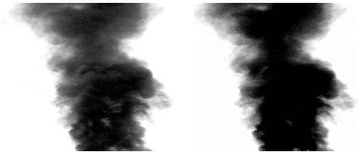
Figure 3.5 Normal and under-exposed smoke plumes. (Image courtesy of Bill Taylor, ASC)
You could make up for underexposure by boosting the image contrast. As the right-hand image in Figure 3.5 shows, this makes the backing white (clear) again, but tonal range is lost (the dark tones block up), the edges of the smoke become harder, and the noise is exaggerated.
Now imagine that instead of a white screen, we’re shooting the smoke plume against a green screen and that the measured green brightness is the same as before. What’s the best exposure for the green screen? Obviously, it’s the same as before. The only difference is that the red- and blue-sensitive layers aren’t exposed.
Just like in the smoke plume, greenscreen foregrounds potentially contain a full range of transparencies, from completely opaque to barely there. Transparent subject matter can include motion blur, smoke, glassware, reflections in glass windows, wispy hair, gauzy cloth, and shadows.
To reproduce the full range of transparency, the green screen should be fully exposed but not overexposed. In other words, its brightness should match the green component of a well-exposed white object like a white shirt, roughly defined as the whitest white in the foreground that still has detail. (It’s not desirable to expose that white shirt as top white, because it’s necessary to leave some headroom for specular reflections, on the shoulder in film, 100% and over in video.)
Setting Screen Brightness
Meter readings of blue and green screens can be misleading. Some exposure meters respond inconsistently to monochrome color, especially blue, and some are affected by the high levels of UV coming from green and blue tubes. The most reliable method for balancing a blue or green screen is still by eye, with the white card method, as discussed next.
White Card Method for Screen Balancing
1. Choose the f-stop at which the scene is to be shot. Let’s say it is f4. Position a 90% reflectance white card in the acting area (Figure 3.6) and light it to an incident light reading11 of f4, keeping the spill light off the backing. The white card is now lit to the brightest tone that still has detail (white-shirt white) even though the actual set lighting may not reach that level.

Figure 3.6 White card in set, lit to shooting stop (incident reading). (Image courtesy of Bill Taylor, ASC)
2. View the white card against the screen through a Wratten No. 99 green filter. (Use a Wratten No. 98 blue filter for a blue backing.) In a pinch, primary green or primary blue lighting gels, folded to several thicknesses, will serve.
3. Adjust the backing brightness so that the white card blends into the backing. The overlay in Figure 3.6 shows the view through the filter. When the edges of the card are invisible or nearly invisible, the green light coming from the screen is now the same brightness as the green light component coming from the f4 white card. (If you were to photograph the white card now, the red, blue, and green components coming from the card would reproduce near the top of the straight-line portion of the curve. Since the green screen matches the brightness of the green component coming from the white card, the green layer will also be exposed near the top of the straight-line portion of the curve, without overexposure.) The backing will now expose properly at f4.
If it is easier to adjust set lighting than backing brightness, the procedure can be reversed. Adjust the white card’s light until the card blends in, and then take an incident reading. Light the set to that f-stop.
Once the backing brightness is set, a spot meter may be calibrated for use with the appropriate color filter to read f-stops directly: Wratten No. 98 (or 47B + 2B) for blue, and Wratten No. 99 + 2B for green. [The UV filters (built into the No. 98) ensure that UV from the tubes does not affect the reading.] Simply adjust the meter’s ISO speed setting until the reading from the screen yields the target f-stop (f4 in the example above).
Just as in the smoke plume example, more exposure is counterproductive; it pinches out fine detail due to image spread and pushes the backing values into the nonlinear range of the film or video sensor. Less exposure is also counterproductive; it would then be necessary to make up matte density by boosting contrast.
Levels for Digital Original Photography
Most of the same considerations apply as in film photography. It’s particularly important that none of the color channels be driven into highlight nonlinearity or “clip,” allowing some headroom for specular highlights. If the screen lighting can be adjusted independently of the set, light the screen to a video level of about 90% in the appropriate channel.
Choosing the Backing Color
The choice of backing color is determined by the costume or subject color. The range of permissible foreground colors is wider when the backing can be lit separately from the actor, rather than when the actor must be photographed in a white-lit green set (a floor shot), for example.
A blue backing is satisfactory for most colors except saturated blue. Pastel blues (blue eyes, faded blue jeans, etc.) reproduce well. The color threshold can be adjusted to allow some colors containing more blue than green (such as magenta/purple) into the foreground. If too much blue is allowed back into the foreground, some of the blue bounce light will return. Therefore, if magenta costumes must be reproduced, it is prudent to take extra care to avoid blue bounce and flare. Keep the actors away from the backing, and mask off as much of the backing as possible with neutral flats or curtains. Saturated yellows may produce a dark outline that requires an additional step in post to eliminate. Pastel yellows cause no problems.
A green backing is satisfactory for most colors except saturated green. Pastel greens are acceptable. Saturated yellow will turn red in the composite unless green is allowed back into the subject, along with some of the green bounce or flare from the original photography. The same precautions as above should be taken to minimize bounce and flare. Pastel yellow is acceptable. Figure 3.7 shows a test of green car paint against a green screen. The hue and saturation of the “hero” swatch was sufficiently distinct from the screen color to pose no difficulties in matting or reproduction, and there is no green spill. Note that none of the colors in the Macbeth chart is affected except for the more saturated green patches.

Figure 3.7 Green and blue paint swatches test against a green screen, before and after. (Image courtesy of Bill Taylor, ASC)
Because bounce is unavoidable where the actor is surrounded by a green floor or virtual set, one should not expect to reproduce saturated magenta or saturated yellow on a green floor without assistance in post.
If the foreground subject contains neither saturated green nor saturated blue, then either backing color may be used. However, the grain noise of the green emulsion layer on color negative and the green sensor in a digital camera is generally much lower than the grain noise of the blue layer. Using a green backing will therefore result in less noise in shadows and in semitransparent subjects. Black smoke in particular reproduces better against a green backing.
Obviously, it is important for the VFX Supervisor to be aware of wardrobe and props to be used in traveling matte scenes. Sometimes a difficult color can be slightly changed without losing visual impact, thus saving much trouble and expense in post. If in doubt, a test is always worthwhile. The Ultimatte previewer (see later section titled On-Set Preview) can be invaluable.
Some visual effects experts prefer blue backings for scenes with Caucasian and Asian actors because it is easier to achieve a pleasing flesh tone without allowing the backing color into the foreground. For dark-skinned actors, either backing color seems to work equally well.
In extreme cases (for example, if the foreground contains both a saturated green and a saturated blue), troublesome foreground colors can be isolated (with rotoscoping if necessary) and color corrected separately.
Backing Types and Lighting
The color and illumination of the backing are crucial to a good result. A perfect green backing would expose only the green-sensitive element of the color negative or digital sensor. Crosscolor sensitivity in the negative or sensor, imperfect illuminators, and spill light from the set all compromise this ideal. It’s no surprise that the best combinations of backing, illuminators, and camera type yield the best-quality composites.
Backlit Backings
Backings can be backlit (translucent) or frontlit. Translucent backings are almost extinct due to their high cost, limited size, and relative fragility. Translucent Stewart blue backings gave nearly ideal results and required no foreground stage space for lighting. Due to lack of demand, Stewart has never made translucent green screens. Frontlit backings are more susceptible to spill light, but with careful flagging they can produce a result every bit as good as backlit screens.
Translucent cloth screens can be backlit effectively, but seams limit the usable size.
Frontlit Backings
If the actor’s feet and/or shadow do not enter the background scene, then a simple vertical green or blue surface is all that is needed. The screen can be either a colored fabric or a painted surface. Any smooth surface that can be painted, including flats, canvas backings, and so forth, can be used. Fabrics are easy to hang, tie to frames, spread over stunt air bags, and so on. Please see the Illuminators section above for spacing and positioning of lamps.
Day-Lit Green and Blue Backings
For big exterior scenes, authentic sunlight makes a very believable composite that can only be approximated with stage lighting.
Daylight is the ultimate challenge, requiring the best quality backings and screen correction compositing for good results. Thanks to those advances, there are no limits to the size of a traveling matte foreground, aside from the size of the backing.

Figure 3.8 Daylight greenscreen composite from Greedy. (Image courtesy © 1994 Universal Studios Licensing, LLLP. All rights reserved.)
Coves as shown in Figure 3.8 (the first daylight greenscreen shot made for a feature film) are to be avoided; there is usually a wide band of glare in the cove. Later experience has shown that a clean, straight line is much easier to deal with in post. A raised platform, painted or covered with backing material, with a separate vertical backing well behind it is ideal. The cinematographer of Journey to the Center of the Earth (2008), Chuck Schuman, recommends a flat 45-degree join between green floors and walls.
Limits of Day-Lit Backings
Because the green backing set must be oriented to achieve the sun direction matching the background plates, one can shoot relatively few setups in a day. At some times of year, the sun on the set may never get high enough to match the background sun, thus requiring a replacement source.
Floor Shots, Virtual Sets
If the actor must be composited head-to-toe into the background scene, as in Figure 3.8, then the floor must also be the color of the backing. (Green is preferred for floor shooting since the shadows will be less noisy.) The same type of white light and lighting fixtures that light the actor are also used to light the floor and backing. A shadow cast on a green-painted wall or floor by the subject can be transferred (when desired) into the background scene together with the subject.
Floors may be painted or covered with fabric. Fabric can be hazardous if loose underfoot. Painted floors scuff easily and quickly show shoe marks and dusty footprints.
Pro-Cyc’s Pro Matte plastic material is a good alternative for floors. The material is a good match to Digital Green and Digital Blue paint and fabric. It is tough, scuff resistant, and washable. It is available in sheets, preformed coves, and vertical corners in several radii. Permanent sets are good candidates for this material, due to cost.
Lighting uniformity problems (within plus-or-minus one f-stop), color contamination of the floor, scuff marks, and green set piece shadows can be dealt with in compositing when screen correction frames are available.
Sheets of 4-by-8-foot mirrored Mylar or mirrored Plexiglas may also be used as a walking surface. (Please see section titled Illumination and Reflections from the Backing below). Of course, no shadow is cast on a mirror surface, and the reflection must be dealt with.
The choice of fabric and paint affects not only the quality of the composite but also the lighting costs. Some screen materials are much more efficient than others, requiring many fewer lamps to light to the correct level. In general, green screens and tubes are more efficient than blue screens and tubes. Savings on lamp rentals can amount to tens of thousands of dollars per week on large backings.
Limitations of Floor Shots and Virtual Sets
Floor shots and virtual sets are both difficult and rewarding, because the actor can walk or sit on objects in the background, climb stairs, and walk through doorways, even when the background scene is a miniature. When the actor’s shadow appears in the background scene, it adds believability to the shot.
Alpha channel (matte) contrast must be high in a floor shot to achieve separation from the contaminated color of the floor. Even the finest green pigment or dye reflects significant quantities of red and green. The problem is often compounded by glare from backlighting. Since the matte is created by the difference between the backing color and the colors in the subject, and since there is inherently less difference because of white light contamination, the alpha values must be multiplied by some factor to yield an opaque matte that will prevent the background from showing through. This multiplication raises the gamma (contrast) of the matte image.
If the real shadow can’t be reproduced, it can be simulated within limits with a distorted copy of the alpha channel. If necessary, the shadow can be hand animated.
Foreground Lighting
Creating the Illusion: Lighting to Match the Background
Inappropriate lighting compromises a shot the instant it appears on screen, whereas an imperfect compositing technique may be noticeable only to experts.
Obviously, the foreground photography must match the background lens and camera positions, but lighting considerations are just as important. This is why it is generally preferable to shoot live-action backgrounds first. (If the background hasn’t been shot yet, the job depends on everything from careful map reading to educated guesswork! Even the best guesses can be defeated by unexpected weather.)
Foreground lighting must match the background in direction, shadow hardness, and key-to-fill ratio. True sunlight has nearly parallel rays coming from a single point at a distance that’s optically equivalent to infinity. To simulate the sun, use the hardest source available, as far away as the shooting space will allow. Multiple sources cast multiple shadows—an instant giveaway. Sometimes folding the light path with a mirror will allow the hard source to be farther away, a better representation of the parallel rays of the sun. Skylight fill and environmental bounce light must be shadowless. Therefore, surrounding the actors with the biggest, broadest sources of light available is preferable. The perfect skylight source would be a dome like the real sky, which can be approximated on stage by tenting the set with big silks or white bounces.
Environmental Bounce Light
Since the software drops out the backing and the backing reflections from the foreground object, the subject is “virtually” surrounded by black. The black surroundings cause no problem if the composite background is an essentially dark night scene.
However, if the eventual background is a light day scene, and if the subject had really been in that day environment, the environmental light would light up the hair and provide the normal edge brightness along arms, sides of the face, and so forth. The cinematographer must light the back and sides of the subject to provide about the same amount and direction of lighting the environment would have provided. Large, white bounces are useful in creating back cross-reflection sources just outside the frame. Otherwise, edges of arms, legs, and faces will go dark, causing the foreground to look like a cutout.
Simulated light from the environment can be added digitally to replace the suppressed screen color with color derived from the background. It’s a slight glow around the edges that can look good when tastefully applied. The real thing is preferred, though.
High levels of fill light in wide day exteriors, although sometimes desirable for aesthetic reasons, hurt the believability of day exterior composites. Movie audiences are accustomed to seeing more fill in close-ups, a common practice in daylight photography.
Local Color
Skylight is intensely blue, so fill light supposedly coming from the sky should be blue relative to the key. Likewise, if actors and buildings in the background are standing on grass, much green light is reflected upward into their shadows. If the actor matted into the shot does not have a similar greenish fill, he will not look like he belongs in the shot. Careful observation is the key. In a greenscreen shot, the bounce light from grass is low in both brightness and saturation compared to the screen color, so that color cast can be allowed in the composite foreground while still suppressing the screen. The same is true of sky bounce in a bluescreen shot.
Shooting Aperture
A day exterior shot will often be shot in the f5.6 to f11 range or with an even deeper f-stop. Fortunately, efficient lighting and high ASA ratings on films and sensors permit matching these deep f-stops on the stage. In a day car shot, for example, holding focus in depth from the front to the rear of the car contributes greatly to the illusion.

Figure 3.9 Green screen lit to f11 with fluorescent lamps. (Image courtesy of Bill Taylor, ASC)
Figure 3.9 shows a 28-foot-wide screen lit with 16 four-tube Kino Flo lamps, plus two HMI helper lamps with green filters on the sides. This combination made it possible to film at f11 with a 200 ASA Vision 2 negative. Curtains at left, right, and top made it easy to mask off unwanted portions of the screen.
Color Bias in Foreground Lighting
In the past, some cinematographers used an overall yellow or magenta color bias in foreground lighting to help the composite, with the intent that the bias be timed out later. This practice is counterproductive, resulting in false color in blurs and transparencies. If an overall bias is desired, it’s easy to achieve in post-production.
Illumination and Reflections from the Backing
Colored illumination and reflections from the backing on the subject must be minimized for top-quality results. Illumination and reflection are separate issues!
Blue illumination from the backing can be made negligible by keeping the actors away from the backing (at least 15 feet, but 25 feet is better) and by masking off all the backing area at the backing that is not actually needed behind the actors. Use black flags and curtains. (The rest of the frame can be filled in with window mattes in compositing.) Any remaining color cast is eliminated by the software.
Reflections are best controlled by reducing the backing size and by tenting the subject with flats or fabric of a color appropriate to the background. In a common worst case, a wet actor in a black wetsuit, the best one can do is to shoot the actor as far from the screen as possible, mask the screen off as tightly as possible, and bring the environmental bounce sources fully around to the actor’s off-camera side, without, of course, blocking the screen. A back cross-light will of course wipe out any screen reflection but will look false if it’s not justified by the background lighting.
Big chrome props and costumes present similar challenges. Since they also present the cinematographer with a huge headache (every light shows, and sometimes the camera crew as well), it is usually not too difficult to arrange modifications to these items. When the visual effects team is brought in early on, problems like these can be headed off in the design stage.
A common reflection challenge is a Plexiglas aircraft canopy, which can show every lamp and bounce source, depending on the lighting angle and camera position. A bounce source for a canopy shot must be uniform and surround the canopy 180 degrees on the camera side. Sometimes the best solution is to shoot without the canopy and track a CG model canopy back in, in the composite. An advantage to a CG canopy is that it can reflect the moving composited background.
Some reflections can be disguised with dulling spray, but sometimes they cannot be eliminated. In the worst case, reflections make holes in the matte that must be filled in digitally in post. Pay particular attention to the faces of perspiring actors, which can be very reflective. Of course, when the actor must stand in the middle of a blue-painted virtual set, some blue contamination is unavoidable; it will be removed by the compositing software.
Sometimes reflections are desirable! Sheets of mirror Mylar or Plexiglas can extend a screen by reflection, even below the stage floor. Actors can walk on mirror Plexiglas to be surrounded by the screen’s reflection. (Of course, their own reflection must be dealt with.)
In a scheme devised by the late Disney effects wizard Art Cruickshank, ASC, an actor on a raft in a water tank was shot against a sodium matte backing. The backing and the actor reflected strongly in the water. This enabled the Disney optical department to matte the actor and his reflection into ocean backgrounds. Cruickshank’s method was revived and used effectively in bluescreen shots in Daylight (1996) (Figure 3.10) and more recently in greenscreen shots in Bruce Almighty (2003), where Jim Carrey and Morgan Freeman seem to be walking on Lake Erie while actually standing in shallow water tanks on the back lot (Figure 3.11).
In Figure 3.10, which shows a diagram of the swimming tank setup for Daylight (1996), the spillway in front of the screen makes a seamless transition from the screen reflection in the water to the screen itself.

Figure 3.10 Water tank diagram. (Image courtesy of Bill Taylor, ASC)

Figure 3.11 Bruce Almighty (2003) water tank composite. (Image courtesy © 2003 Universal Studios Licensing, LLLP All rights reserved.)
Controlling Spill Light
Attentive use of flags and teasers on set lighting and black cloth on light-reflecting surfaces outside the frame will eliminate most spill light on the backing. (Even concrete stage floors reflect a surprising amount of light. To see spill light when the backing is lit, look through a red filter.) A small amount of white spill light from the set inevitably hits the backing. It often comes from the large, almost unflaggable soft sources that simulate skylight. Since the skylight is typically two or three stops down from the key light, the spill has little effect on the backing. Realistic lighting should be the paramount concern.
If white light is contaminating an area of the backing, a higher level of the alpha channel can be applied in post to darken it. Since there is no difference in color between, say, transparent white smoke or mist and white light of the same brightness falling on the backing, it’s clear that the less white light contamination there is to be cleaned up, the better. Otherwise, as the contamination disappears, so do all the transparent foreground pixels of the same color. Screen correction is invaluable in extracting the maximum detail from smoke and spray shot against white-lit backings.
If the foreground must be flat lit to simulate overcast conditions, a good approach is to bring most of the light in from overhead through a large, translucent silk. On stage, much of the overhead soft light may be kept off the backing with a series of horizontal black teasers hung directly beneath the silk, running its entire width parallel to the backing. The teasers are progressively longer top to bottom as they get near the backing, preventing the backing from “seeing” the silk (see Figure 3.11 above).
Lighting Virtual Sets
Inescapably, if one is lighting an actor and the surrounding floor with white light, there is no way to control the floor brightness independently of the actor, other than changing the floor paint or floor fabric. The only control available is the balance between the actor’s shadow and the rest of the floor and backing.
Lighting Procedure for Holding the Shadow (Petro Vlahos Technique)
1. Turn on the key light to cast the desired shadow.
2. Measure the brightness on the floor just outside the shadow (use a spot brightness meter and green filter, assuming that it’s a green floor).
3. Light all the rest of the green floor to this measured brightness while adding as little light as possible to the shadow area.
4. Light the green walls to achieve the same brightness as the floor.
5. Shadow density may be increased by blocking fill light from the shadow area or lightened by adding fill light to the shadow area.
Shadow density is controlled by adjusting the fill light, not by adjusting the key light. Outside the shadow, the entire green set should appear to have equal and uniform intensity as seen from the camera position. Strive to stay within plus-or-minus 1/3 f-stop; screen correction can deal with brightness variations as great as plus or minus one f-stop.
The human eye quickly compensates for small light changes; it is not a good absolute measuring device. (It is, however, superb at comparisons.) It is necessary to use a spot brightness meter and green filter to check for uniform brightness. A digital camera with a computer display is also useful for making a quick check of lighting uniformity in the three-color channels.
In backlight, because of the shallow angle between the camera and floor, the floor will not appear as green as the back wall. A diffused, polarized white-light glare component is reflected by the floor because of the shallow angle. For holding good shadows in backlight, it is essential to use a polarizing filter over the camera lens. The HN38 is recommended. Rotate the filter until the floor glare is canceled. Ideally, the backlights should be polarized too, but it is rarely done. Large sheets of polarizing plastic are available up to about 19 feet wide; they can be protected against heat with heat shield reflecting filter material. Of course, HMIs emit less heat than tungsten lamps to begin with.
Lighting to Eliminate the Shadow (Vlahos Technique)
1. Light the entire green set uniformly with large-area diffused light sources.
2. Check uniformity as noted above.
3. Place the actor in position. If he casts a shadow, add additional low-level lighting to return the light level in the shadow to its original level.
4. Add a modest key light to create the desired modeling, and ignore the shadow it casts. The added key light will cause a shadow to be visible to the eye, but because the key light did not affect the green intensity of the floor in the shadow it has created, the shadow can be made to drop out in compositing.
Tracking Marks on the Screen
When the foreground camera moves, the background must move appropriately. Unless the foreground and/or background can be photographed with a motion control camera, tracking data must be extracted from the foreground image and applied to the background during compositing. This process is called matchmoving.
Tracking marks applied to the otherwise featureless screen give the matchmovers fixed points to track. These marks must obviously show in the photographed scene, but ideally they should clear the foreground actors, or at least avoid their heads, since they must be removed in the composite. Marks are typically laid out in a rectangular pattern, with about 3 to 5 feet between them, depending on the lens used, the action, and the distance to the backing. Black or white tape pieces or crosses will usually suffice, though uniquely identifiable markers are very helpful if there is much tracking to do.
If camera shake or other sudden motion is required in the foreground photography, motion blur can obliterate the tracking marks. The Aerocrane Strobe Tracking System created by Alvah Miller provides target arrays of LED lamps that strobe in sync with the camera shutter, giving well-defined marks on every frame even if they are not in focus. Cylindrical LEDs have uniform brightness even when viewed off-axis.
Sometimes it is desirable to light the tracking LEDs continuously, allowing them to blur in motion. Valuable tracking information can be derived from the length of the blur. Consult the tracking team for their preference.
On-Set Preview
On-set preview composites made with a still camera and calibrated monitor, like the Kodak/Panavision Preview System, or a live composite made with a hardware Ultimatte device will alert the crew to problems before they are committed to film. A few video assist companies provide this specialized service.
Using the digital Ultimatte previewer (hardware device or software on a computer) on the motion picture set eliminates much guesswork and uncertainty. It provides great assistance when photographing actors who must be realistically integrated with people and objects in the background scene. Previewing with Ultimatte also immediately identifies the acceptable limits in lighting irregularities and wardrobe color.
If it’s a digital shoot, an output video stream must be available that’s compatible with the Ultimatte. An outboard processor may be needed. This yields the best preview available with all the foreground-background relationships visible at full quality.
For film shoots, a small, outboard color camera feeds the previewer. (Film camera color taps, even when they can be switched to 100% video, are so starved for light that they usually cannot make good composites, although if their geometry is properly adjusted, they are fine for alignment purposes.) Playback from disk or tape provides the background scene.
Camera for Bluescreen or Greenscreen Photography
Film Photography: Choosing a Camera Negative
Some camera negatives are better suited to composite work than others. Ideally, one would choose the finest grained, sharpest film available. It is also important to have low cross-sensitivity between the color layers. Foreground and background film stocks do not have to match, but of course it’s helpful if they have similar grain and color characteristics.
Kodak Vision 2, 100T and 200T (tungsten balance), films are ideal for green and blue backing work. The dye clouds are very tight and well defined. Vision 3, 500T, the latest in a series of remarkably fine-grain high-speed films, as one would expect, is still grainier than the lower speed films. Although the 500T film is not ideal, a well-exposed 500T negative is much better than a marginally exposed 200T negative!
An interlayer effect in these films produces a dark line around bright foreground objects (such as white shirts) when they are photographed against a green screen. Software can deal with this effect.
Kodak Vision 2, 50-speed daylight film and Fuji 64 daylight film produce superb results in sunlight, with very low shadow noise, but require high light levels on stage.
If these 100T and 200T films cannot be used for aesthetic reasons, one should still pick the finest grain emulsion compatible with lighting requirements. Be aware that additional image processing (and cost) may be required. A few negative emulsions have so much cross-sensitivity between the color layers that they should not be used.
Film emulsions are constantly evolving. As an example, recent improvements in red sensitivity in some emulsions have been accompanied by more sensitivity to infrared reflected from costumes, altering their color noticeably. This effect is easily dealt with by filtration—if you know it’s there! A quick test of actors and costumes is always worthwhile.
Choosing a Digital Camera
Since all three-color channels are used in creating the composite, an ideal camera would have high resolution and uncompressed color (bandwidth).
Three major factors affect color recording:
1. spatial resolution,
2. captured bit depth, and
3. recorded bit depth and compression.
Spatial Resolution
Spatial resolution is broadly related to the number of photosites (light-sensitive elements) available for each color. In the commonly used Bayer array there are half as many blue photosites as there are green photosites. Likewise, there are half as many red photosites as green photosites. The missing values are derived through interpolation from adjacent pixels in the de-Bayering operation. Because human visual acuity is greatest in the green wavelengths, Bayer’s array gives excellent visual results from an optimally small number of photosites. Although they are not ideal for the purpose, Bayer array cameras can yield good composites with care in original photography and in post.
However, the blue and red image is still half the resolution of the green image, which limits the resolution and fine detail of the mask image.12 To address this and other image quality issues, a few high-end cameras like Panavision’s Genesis and Sony’s F35 (same sensor as the Genesis) have full resolution in all three colors. These cameras are ideal for composite work.
Color Bandwidth and Compression
Assuming your camera can produce a full-bandwidth, uncompressed RGB signal, much information can be lost when that signal is compressed and recorded. Many HD VCRs are limited to 4:2:2 recording, which includes rolling off the green channel’s high frequencies and applying half-bandwidth MPEG compression to blue and red.
The designation 4:2:2 does not refer directly to RGB bandwidth but rather to YUV. The Y channel carries the luma or brightness information, while U and V are the channels from which the color information is derived (similar to LAB color space in Photoshop). In a 4:4:4 recording, every channel is recorded at the full color depth. (The designation 4:4:4 is actually a misnomer, carried over from standard definition D1 digital video. Because it’s well understood to mean full bandwidth in all three channels, its use has continued into the high-definition and higher digital cinema world.)
Just as the classic Bayer array has a negligible effect on images intended for viewing but adversely affects composite quality, well-compressed images designed to look good on screen can have serious limitations when composited. Good software engineering can recover some of the lost bandwidth, but edge detail (fine hair and so forth) and shadow noise still suffer from compression artifacts. A laundry list of compression artifacts includes dark or light lines trailing or leading moving objects, banding in dark areas, and so forth. These problems are even more pronounced in “DV” and “SD” format cameras. With new cameras coming on line every day, testing on the actual subject matter is always worthwhile.
Edge Enhancement/Sharpening/Detail Settings
Camera edge enhancement/sharpening should be turned off! The artificial edges that sharpening produces will otherwise carry into the composite. If sharpening is needed, it can be done during compositing.
Recording
Recording in data mode gives maximum flexibility and best quality in post. Data mode records the uncompressed data (as directly off the camera sensor as the camera’s design allows) to a hard disk. This is often called raw mode, but beware: At least one camera’s (Red) raw mode is in fact compressed. Since raw mode data cannot be viewed directly, a separate viewing conversion path is required to feed on-set monitors.
If recording in data mode is not possible, shoot material intended for post-compositing as uncompressed 4:4:4 full-bandwidth HD (or better) video onto a hard drive or use a full-bandwidth VCR, such as Sony’s 4:4:4 SR format machines.
To sum up, resolution numbers are not the whole story, since some cameras trade off resolution for color depth. Test your available camera and recorder choices.
Because this is an imperfect world, you may have no choice but to shoot or record with 4:2:2 equipment. Although 4:2:2 is not ideal, don’t forget that the last two Star Wars films, which included thousands of greenscreen, were shot with 2/3-inch 4:2:2 cameras. Test the camera on the subject matter. Note that 4:2:2 can produce a satisfactory result in green screen (since the green channel has the highest resolution in these cameras), but one should not expect the ultimate in fine edge detail. (Consumer cameras typically record 4:1:1 and are not recommended for pro visual effects use.)
It bears repeating: Whatever the camera, any edge enhancement/sharpening should be turned off!
Filtration
In general, no color or diffusion filters other than color-temperature correction should be used on the camera when shooting green-screen or bluescreen work. Compositing can be called “the struggle to hold edge detail”; obviously low-contrast, soft effects or diffusion filtering that affects the edge or allows screen illumination to leak into the foreground will have an adverse effect.
To ensure that the filter effect you desire will be duplicated in the composite, shoot a short burst of the subject with the chosen filter, making sure it is slated as filter effect reference.
Negative Scanning and Digital Conversion
The film frames, data recording, or video recording must be converted into frame-based digital files the software can use. It’s important not to lose information at this step.
The three layers of the color negative are sensitive exclusively to the red, green, and blue portions of the color spectrum. When the negative is scanned, the RGB densities of each pixel in the image are translated into red, green, and blue numerical levels in a digital memory. The three color records of each frame are referred to as the red, green, and blue channels. They are usually recorded as Cineon or DPX frames, which are uncompressed formats.
Video and data must be similarly converted into frames. This step is sometimes called digitization, which is really a misnomer since the source is already digital. These frames are usually recorded in the DPX format.
Color Correction
Color correction at the scanning/conversion stage can be a major source of data loss. It should not be built in to image files intended for compositing. On the other hand, a few frames recorded with the desired color and filtration will be an invaluable reference during the composite step.
Software Functions
The software uses the difference between the backing color and the colors found in the foreground to accomplish four tasks:
1. Optimally, it will correct nonuniformity in the backing (the screen correction function, not available in all software packages).
2. It must create a silhouette matte (the alpha channel) of the foreground action (Figure 3.12, center frame).
3. It must create a processed foreground in which all traces of the backing color are suppressed (turned black or neutralized), while the foreground color is carried through unchanged (Figure 3.12, right frame).
4. Finally, it must bring all the elements together into a believable composite with the background (Figures 3.13 and 3.14). In the example shown, the greenscreen foreground was shot on an outdoor set, freely following the action with a Steadicam. Motion tracking information derived from the Steadicam foreground was applied to the panoramic combined background plate. (In the process of making the background, the Horseshoe Falls and the American Falls were moved one-half mile closer together.)
Figure 3.12 Original photography, silhouette (alpha) matte, and processed foreground from Bruce Almighty (2003). (Image courtesy © 2003 Universal Studios Licensing, LLLP. All rights reserved.)

Figure 3.13 Background seamed together from three VistaVision images. (Image courtesy of Bill Taylor, ASC)

Figure 3.14 Three frames from Bruce Almighty (2003) Steadicam shot. (Image courtesy of Bill Taylor, ASC. © 2003 Universal Studios Licensing, LLLP All rights reserved.)
The Processed Foreground
The original image contains the green backing and the foreground subject. The green backing is automatically reduced to a black backing by a logic operation, and subtracting a proportion of the alpha (matte) signal in each channel. Green is limited so that it cannot exceed red or blue. As a result, all of the green color seen though transparent and translucent subjects likewise disappears.
If the foreground subject (actor) is close to the backing or standing on a green floor, the subject will have a green color cast due to reflected (bounce) light from the floor and from lens flare. (This reflected light from the screen is sometimes called spill, but it should not be confused with the spill light from the subject’s lighting falling on the screen.) No attempt should be made to remove this color with filters on the lights or camera, or with color correction in transfer. All backing contamination is removed from the subject by the software’s white, gray, and black balance controls.
Blue bounce is much harder to see on the set than green but is just as visible in the composite. There is no difference between green screens and blue screens of the same brightness as far as bounce is concerned. A dark blue or green will bounce less, but dark colors have too little color saturation to make a high-quality matte.
Once the backing has been reduced to black, and color contamination of the subject has been eliminated, the subject appears to have been photographed against a perfectly black backing. No evidence of the backing color remains. This is the processed foreground image.
The order in which the foreground is processed is important. Noise reduction on the foreground should happen when the processed foreground is made, before the alpha is created, whereas color correction should wait until the final composite.
Underwater Photography
In addition to underwater diving or swimming shots, underwater greenscreen photography creates a zero-g environment for space-suited actors who have freedom of motion that is impossible to achieve on wire rigs.
The biggest challenge is keeping the water clear of sediment and particulates. Underwater diffusion causes the screen to flare into the foreground and vice versa; it’s ruinous to the matte edges. High-capacity pumps, good water circulation, and a multistage filter are necessary to keep the water clear. It’s also important that all personnel have clean feet when they enter the tank.
Composite Components’ green material stretched on a frame works well under water in a swimming pool or a tank. Tip the screen back to catch light from above, with diffusion material floating on the water surface to kill caustic patterns on the screen. Build up the screen lighting level with green fluorescent units above the water. Underwater Kino Flo lamps are also available.
The high chlorine levels common in swimming pools bleach out the screen quickly; pull the screen out of the tank daily and rinse it off with tap water.
Working with the Cinematographer
The cinematographer is the visual effects creator’s most important ally on the set. So much depends on the quality of the original photography! Befriend the Cinematographer early in the game, and keep him or her in the loop!
Invariably, the Cinematographer is eager to help achieve the best final result. Be sure he or she understands and believes that you can duplicate any final look required, if (for example) you need to shoot without diffusion on the lens. Be sure to shoot properly slated reference with the desired diffusion, filtration, and so forth, so that it can be matched in the composite.
Please refer to the ASC manual, which has a similar chapter on blue screens and green screens.
The Alpha Channel
The alpha or matte channel (the channel that carries transparency information) is a grayscale image in which the foreground image is a silhouette. The silhouette may be imagined as black against clear (and all the values in between) or, with its values inverted, clear against black.
The alpha channel represents the difference in color (hue, saturation, and brightness) between the backing color and the colors in the foreground subject. The matte’s numerical level at any pixel is proportional to the visibility of the backing.
Compositing Software
Bluescreen and greenscreen compositing software is sometimes lumped into the collective category of keyers. Unfortunately, some early keyers such as Chroma Key were so crude that they harmed the reputation of the whole class by association. The present-day software described next has no relationship to those early keyers.
The software described in the following paragraphs is in wide use. All except IBK are available as plug-ins for most of the leading digital compositing packages, including After Effects, Nuke, Flame/Inferno, and so on. All contain filters to deal with less-than-ideal video like DV.
Each package has individual strong points; all are capable of first-class results with well-shot photography. Sometimes the best results come when two programs are used on a single shot. This list is by no means inclusive.
Keylight
At this writing, Keylight is the most used package, thanks to its bundling with After Effects Professional software. A straightforward user interface makes it very easy to use. Keylight has excellent edge transition controls and plenty of power to deal with off-color backings. The background scene may be used to influence the edges of the composite.
Keylight was developed originally at London’s pioneering Computer Film Company by Wolfgang Lempp and Oliver James. It is marketed worldwide by The Foundry.
Ultimatte
Ultimatte and Ultimatte AdvantEdge are the tools of choice for difficult shots. AdvantEdge borrows from Ultimatte’s Knockout concept by processing the edge transitions separately from the core of the foreground image, blending them seamlessly into the background without loss of detail.
The deep and rich user controls require an experienced operator to get the most from the software. The interface works as a black box within the compositing package, which can complicate workflow. One benefit of this architecture is that the interface is identical in the wide range of supported software packages.
The first-of-its-kind software was derived from the original Color Difference logic created by Petro Vlahos; Richard Patterson (then at Ultimatte) wrote the first digital version. The commercial digital implementation won multiple Academy SciTech Awards. Ultimatte HD and SD video hardware compositing devices are also available from the company.
Primatte
Primatte was originally developed at Imagica Japan by Kaz Mishima. The unique polyhedral color analysis allows fine-tuned color selections between foreground and background. The user interface is intuitive and uncomplicated while offering many options. The background scene may be used to influence the edges of the composite. It is bundled into Nuke.
The IBK (Image-Based Keyer)
The IBK was developed by Paul Lambert at Digital Domain. It is exclusively bundled with Nuke. It employs Ultimatte code carried over from earlier compositing software packages like Cineon and Rays, by agreement with Ultimatte. Like Ultimatte, it can deal with a wide variance in backing color by creating a synthetic clean plate. As in Keylight, the background scene may be used to influence the edges of the composite.
Updated contact information for these suppliers is listed in this book’s companion website (www.VESHandbookofVFX.com).
With Thanks to Petro Vlahos
This document draws heavily on the Traveling Matte chapter that Petro Vlahos and the present author wrote for the last three editions of the ASC manual. Vlahos, a multiple Oscar winner, created the perfected Color Difference bluescreen film system in 1958 and in the following years led the creation of analog and digital hardware and software versions of Ultimatte, the first high-quality electronic compositing systems. At their core, all digital blue-screen and greenscreen compositing software systems employ variants of the original Vlahos algorithms.
ON-SET DATA ACQUISITION
Karen Goulekas
Ensuring that the proper visual effects data is gathered while shooting a film is one of the most important aspects of a VFX Supervisor’s job. Decisions made about what data to get, and how to acquire it, will determine how efficiently the visual effects vendors will be able to create their final shot work in postproduction.
A poorly planned visual effects plate shoot can result in wasting precious post-production time and money solving technical issues, rather than using the time on aesthetic and creative issues that will make the shot better. Examples of things that can make visual effects shot creation less than ideal include missing camera lens data, badly lit or nonexistent chroma screens, no (or too many) tracking markers, and rig removals that could have been better hidden in frame.
However, although it is the job of the visual effects team to gather this data, there are definitely circumstances when it is not feasible. For example, sometimes a plate shot on location that was not intended for visual effects work may very well become a visual effects shot in post as the edit comes together. And although it may not be an ideal plate, the hope is that, at the very least, the camera information can be found in the script supervisor’s and/or camera assistant’s notes—copies of which should always be obtained before the end of the shoot.
Also, due to the high cost of having an entire crew on location each day, it can quite often make more economic sense to choose the “fix it in post” option. The reality is that even if it’s going to take “only an hour” to prepare a chroma screen behind the actors on location, that hour, multiplied by the cost of every crew member on set, can be a far more expensive option than paying extra for one roto artist to manually brute force the way through creating a matte to isolate the actors in the scene. Although this is not an ideal solution, it’s the one that the producer will most likely choose, for the obvious financial reasons. However, although it is important for the VFX Supervisor to be flexible regarding the budget and time issues that are a part of every film shoot, they must consider not only the cost differences but also the potential quality differences, depending on the specifics of the shot. A poorly executed final shot won’t be of any value to the film, regardless of how many dollars were saved.
Additionally, when a scene is taking place during sunrise or sunset (the magic hours), gathering the ideal visual effects elements, such as a clean plate or HDRI stills with all the actors and crew cleared from the set, will simply not take priority over filming all the required shots in similar lighting. Even something as quick as placing tracking markers cannot take priority over shooting the required action in the desired light. The visual effects team should be prepared to take advantage of any downtime during shooting to prepare and place tracking markers ahead of the shoot day so as to minimize slowing down the live-action shoot and missing the opportunity to gather important data on the day.
Camera Report
That being said, it is still important to plan for getting all the ideal data possible. The first and most basic piece of information is the visual effects camera report. Although the script supervisor and camera assists will be taking their own notes, they tend to only take down the basics, such as the slate number, lens, takes, camera roll, focus, and time of shot.
However, for the visual effects camera report, more data is good data! The on-set data wranglers should get as much info as possible, including the following:
• camera lens and serial number;
• camera roll;
• film stock (if using film cameras);
• filters;
• camera body;
• camera height;
• camera distance from subject;
• pan, tilt, and zoom info;
• time of day;
• weather;
• slate number;
• lighting info; and
• location.
Of course, not all of this data is required for every shot. However, if the data wranglers can get this information unobtrusively, then why not? It might be required to shoot an additional visual effects element for a particular plate later in post and, if so, it sure is nice to know the camera settings and where it was positioned relative to the actors and set.
However, it is important to note that a data wrangler should not gather information that is not mandatory to the creation of a shot if it slows down the camera crew or overall production in any way.
It’s important to have a written description of both the camera’s and actors’ actions. For example, while the actors’ action might be about the actors getting into a car and driving away, the camera action might be a crane shot starting on the actors as they get into the car and then craning up, panning, and tilting with the car as it drives away from the camera. The point is to be able to get a visual on what the entire shot is about based on these written descriptions.
Additionally, notes about the type of camera equipment used, such as dolly track, cranes, camera heads, etc., should also be documented. This is particularly important information if there will be additional plates for the shot, such as a miniature, and a need to re-create the motion control data to export to the camera crew shooting the models. It is also helpful to know how the camera equipment was set up to get the shot if there are any issues solving the camera track for the plate.
Another good practice is to list the 2D and 3D tasks and elements required for each plate shot, such as set extension, sky replacement, wire and marker removal, etc. This is a good way to gauge how many potential shots of each type, such as composite only, set extensions, or CG creature shots, there might be in the final shot list.
Many script supervisors will place a “V” for visual effects in front of the scene number on the slate to indicate when a shot will require visual effects work. It is also recommended to place a visual effects number on the slate of each plate shot that will require visual effects work. This is particularly helpful in editorial as a quick way for the editor and visual effects team to identify which shots in the cut will require visual effects work. Although most visual effects work needed is quite obvious, a visual effects numbering scheme is a sure way to remember wire and marker removals that are, otherwise, hard to spot on the editorial screens. It can also serve as a reminder about less obvious things discussed with the director while shooting, such as sky replacements, color corrections, speed ramps, etc.
For most visual effects projects, the anticipated body of work is generally broken down into specific sequences and shots during pre-production as a means of budgeting and bidding the work to award to visual effects vendors. One typical scenario is to use a two-letter code for each visual effects sequence in the script. For example, shots in a Brooklyn Bridge sequence would begin with “BB,” followed by a four-digit number, such as BB0010, BB0020, etc.
Because multiple units are often shooting, one helpful practice is to assign a unique visual effects slate number for each camera setup that will involve visual effects work. Although any numbering scheme can work, one suggested methodology is to indicate the two-letter sequence code, such as the “BB” mentioned above, and then increment sequentially for each camera setup. It can also help to use a different numbering sequence for each unit—for example, starting at 1000 for main unit, 2000 for 2nd unit, 3000 for 3rd unit, etc. This is a quick way to know which unit shot each plate without having to look up the specific camera report. It is also handy for getting a quick count on how many visual effects plates have been shot overall.
The data wranglers simply start the visual effects camera setup as BB1000, BB2000, etc., depending on which unit they are covering, and then increment by one for each camera and setup that is shot for visual effects. If a particular shot is being covered by three cameras—for example, A, B, and C—each camera should get a unique visual effects number and associated camera report, such as BB1000, BB1001, BB1002.
When multiple cameras are being used as described above, it is also helpful to note on each camera report that it was part of a multicamera shot. For example, the camera report for A camera, named BB1000, should note that it was shot with BB1001 and BB1002.
Because camera slates can get quite full with all the information that needs to be documented about each take, there is often no room left to put the visual effects number. Or even if there is, if it is a tiny space, it defeats the purpose of having the number on the slate if it can’t actually be read off the monitors in editorial during post. To address this, it is good practice to ask the camera assistants to write the visual effects slate number on the back of the camera slate—nice and big! When slating the cameras, they just have to flip the slate over for a moment to record the visual effects number.
Figure 3.15 is an example of a simple camera report filled out with sample data.

Figure 3.15 Camera report with sample data. (Image courtesy of Karen Goulekas.)
Tracking Markers
Tracking markers, in conjunction with the camera lens info, are the best way to ensure the ability to digitally re-create the practical camera motion that created the plate. While many programs are available that can calculate the camera motion with just the camera lens, it’s still a best guess. However, with tracking markers in the scene, the tracking software can use a combination of the camera lens and triangulation of the tracking markers to calculate a more accurate match for what was actually shot.
When placing markers on a chroma screen, it is important to use a marker color that is well separated from the chroma screen color. A good rule of thumb for placing markers on a chroma screen is to place them 5 feet apart, which, in most cases, will ensure that markers show up in the shot. If a CU shot reveals too few markers, a data wrangler should always be ready to run in and place another marker or two to get the coverage needed. However, it is good practice to check with the crew members who will be doing the actual tracking as they might have additional requests or specifics to make their job easier.
Note that it is far better to add extra markers when/if needed, rather than place the markers too close together. On the other hand, too many markers means a lot more work for the compositing team, because it requires more paint-out work and/or multiple keys to accommodate the color of the markers versus the color of the chroma screen. Think twice about the work added to be done in post before plastering the screen with unnecessary markers.
It is also quite helpful to use different shapes for adjacent markers because camera tracking software can get confused when they are all the same. For example, if a particular “X” shape that is being tracked and calculated by the tracking software enters or exits frame during the course of the shot, the tracking software might jump to another “X” shape in the scene to track instead. This problem can be alleviated by using different shapes.
When dealing with placing markers on outdoor locations, any size and shape of markers can be used that will best address the terrain and tracking needs. For example, if the terrain to be tracked is relatively bare, use short markers placed on the ground in the areas where visual effects will be added. In Figure 3.16, tracking information was needed about the ground plane as digital vultures were going to be interacting with it.

Figure 3.16 Sample ground plane marker layout for the film 10,000 BC (2008). (10,000 BC © Warner Bros. Entertainment Inc. All rights reserved.)
However, when faced with high foliage, taller markers are required. In this case, it is best to have stakes cut to a predetermined height so there is always a sense of approximately how high each marker is from the ground plane. Additionally, if Velcro is placed on all four sides of the stakes, the tracking markers can be quickly aligned toward the camera, rather than having to physically move the orientation of each stake for each shot.
When dealing with aerial plates, bigger markers are required. In one shot a grid of traffic cones was placed 15 feet apart from one another. The cones showed up perfectly in the aerial plates and it was very helpful to the visual effects artists to know the height of the cones, as well as their distance apart from one another as a guide to the scale of the location.
When dealing with dark sets or night shoots, LEDs placed around the set are the perfect solution. They show up clearly in the plates and are easy to paint out because they are so small. Also, the type of cloth being used for the chroma screens can determine the best materials to use to create the tracking markers. For example, grip tape works fine for Spandex chroma screens, whereas Velcro-backed markers work best on felt screens.
When visual effects elements will be added to actors, small dots placed on their face and body get the best results. Depending on what needs to be done in post, the number of markers can range from two or three to over a hundred placed in a grid across their face.
In general, the on-set visual effects team should always be armed with a variety of tracking markers, such as grip tape in various colors, LEDs, stakes and rods, precut X’s, etc. However, along with the job of getting tracking markers into the scene quickly and without holding up the shoot also comes the responsibility of quickly getting those markers back out of the scene if the next camera setup does not require visual effects. No point in spending the visual effects budget on unnecessary paint-out work in post.
Props for the Actors
Quite often, actors have to perform and interact with “invisible” characters that will be added with visual effects during postproduction. Not only can it be difficult for the actor to perform without being able to see and interact with his counterpart, but it can also be very difficult to add the digital character in the scene if the actor’s eye line and body motion do not fit with the scale and proportions of the digital character. It also makes it very difficult for the camera crew to frame a shot without knowing how much space the digital character will take up in the final shot composition.
In a situation where the actor just needs to know the size and position of the digital character so he can get his eye line and body oriented correctly, a prop representing the size and position of the digital character may be sufficient.
For example, in Figure 3.17, a full-scale model of the in-progress digital tiger was printed out on fabric and stretched across a lightweight frame. This allowed both the camera operators and actors to rehearse a pass while the data wranglers walked the tiger stand in through the set.

Figure 3.17 Full-scale stand-in model used for camera and actor eye lines for the film 10,000 BC (2008). (10,000 BC © Warner Bros. Entertainment Inc. All rights reserved.)
Then, when the scene was shot without the tiger stand-in, the actors and camera crew already knew what marks and eye lines they had to hit. It is also helpful to shoot a take of the rehearsal as a means of indicating how the shot was envisioned with the digital character during shooting.
If the digital creature is really large, a simple height stick indicating where the creature’s eyes will be can be helpful. For example, in the case of the mammoths in 10,000 BC (2008), they were 18 feet tall. To give the actors a correct eye line, an extendable rod was used and raised up to about 16 feet where the mammoth’s eyes would be. This allowed the actor and camera crew to adjust for the framing and action needed when shooting the plate.
When dealing with lots of extras, make sure that they do not move through the areas on the set where the digital creatures will be added. Again, in the case of 10,000 BC (2008) a technique was needed to indicate the total area on the set that the digital mammoths would require in the final shot as a means of preventing the extras from travelling through that area.
To do this, full size and lightweight mammoth shapes were built to indicate their size and position on set (Figure 3.18). And because space for four mammoths pulling up the stone blocks had to be accounted for, a base was built, representing their total required area, which served as a type of fence that kept the extras out during shooting.

Figure 3.18 Mock-up of elephants on set for the film 10,000 BC (2008). (10,000 BC © Warner Bros. Entertainment Inc. All rights reserved.)
When actors need to physically interact with digital characters, one approach is to have the stunt team interact and fight with the actors using life-size props that represent the digital character. For example, the actors needed to fight and kill various 12-foot-tall Terror Birds in 10,000 BC (2008). Because the actors needed to dodge the strikes of the birds, as well as strike at them with their swords, it made sense to have the stunt team perform as the Terror Birds. To do this, life-size Terror Bird heads were built and attached to rods so that the stunt team could raise the Terror Birds to the correct height and interact with the actors.
Any number of props and techniques can be used, but, unfortunately, most of them, as seen in the images above, do increase the amount of paint-out work needed in post. But that is better than shooting plates blind without any guidance as to where the characters will be and what they will be doing in the final shots.
Cyberscanning
For both props and actors that need to be created or enhanced with visual effects, cyberscanning offers the best solution to quickly gathering a 3D volume of their shape.
Because it can be difficult to have access to actors once principal photography has wrapped, most cyberscanning companies offer mobile services so they can come on location and cyberscan the actors during the shoot. Generally, when doing a full-body scan, it is good practice to have the actor wear a Lycra body suit, rather than the costume. This allows for the costume to be added digitally, as a separate model, so that cloth simulations can be added as needed.
The same holds true for hair. If the character will be relatively large on screen and it will be necessary to create digital hair and simulations, it is better to have the actor wear a skull cap for a clean scan of his head shape rather than have to remove all of his cyberscanned hair in post.
However, if the digital characters will be very small in frame and, therefore, not require any hair or cloth simulations, they can be cyberscanned in full costume. Using this technique, digital photos of the actor in costume can be directly projected right onto the cyberscanned model, thus avoiding the step of creating the costume and hair as separate models.
Digital Photos
For any props or actors that are cyberscanned, digital photos are also needed for use as texture maps and/or reference to create shaders.
When photographing props, it is best to take the pictures in neutral light for use as texture maps. However, taking pictures of the props in hard sunlight and shade is also a good means of seeing how the materials the props are made of react to different light situations.
For photos of digital crowds and extras that will be small on frame, about five photos of each extra in costume should suffice. It is best to photograph them against a white backdrop with no harsh lighting. It is also a good idea to put tape marks on the ground to quickly show the extras where they need to stand for their photos, which helps make things move a long a little faster.
When building a digital character that will be large in frame, many, many photos are needed! While the requirements of each digital character will be different, the number and detail of the range of photos should be relative to how close it will be to the camera in the final shot.
In general, it is a good idea to take photo references of all the props and sets during shooting in the event they need to be built as additional visual effects elements.
When there is a need to photograph large areas for a set extension or to create CG buildings, a good technique is to shoot the photos/textures as tiles. Very simply, the edges of each tile should overlap with the edges of its adjacent tiles to ensure there isn’t anything missing in the scene because it accidentally didn’t get photographed.
For example, if it is necessary to capture a city skyline for use in multiple shots, set the camera up on a tripod and pan and tilt to each section of the skyline, until overlapping tiles representing up to 360 degrees of the environment have been captured. Once these tiles are stitched together, they can be projected onto a dome to give a full 360-degree view of the world to use in the composites.
Lidar/Laser Scanning
Lidar/laser scanning of sets and locations is an incredibly useful tool to get a 3D volume of large areas for use in visual effects. Because lidar is based on line of sight in terms of what it can capture from where it’s set up, the length of time to scan a set or location depends entirely on how crowded that area is.
For example, when scanning a natural location, such as a canyon, the scan can go very quickly because the lidar system can view and scan large areas at a time with few obstructions from any given location. However, when scanning buildings in a dense city, every building is obstructed to some degree by other buildings in the foreground and, therefore, the lidar system requires many more positions to set up and scan from.
To create the digital buildings in The Day after Tomorrow (2004), a lidar team scanned 12 blocks of buildings in New York City in high detail. This took 12 weeks to accomplish due to the many locations required to get full coverage. It also took a lot of time (and money) to get the approvals from the building owners to actually get inside and on top of various buildings from which to scan. During this time, a team of photographers took advantage of the various locations to take thousands of photos for use as textures for the scanned buildings. (Lidar scanning is discussed in more detail in the Lidar Scanning and Acquisition section later in this chapter.)
Lens Distortion Charts
Because camera lenses create varying degrees of lens distortion on the images they capture, shooting lens distortion charts is very helpful in dealing with this issue when creating visual effects.
Since no two camera lenses are the same, a large black-and-white grid should be shot for every lens that was used to shoot the film. So if the main and 2nd unit both used the same range of lenses, it is still necessary to shoot a unique grid for every lens in both kits. By doing so, the unique lens distortion created by each lens will be obvious based on how many the lines of the grid get bowed and distorted toward the edges of the frame.
For best results, the grid should have the same aspect ratio as the film or digital cameras that were used. For example, a grid that is 4 feet by 3 feet can be easily filmed to fill the frame of a full aperture film frame of 2048 × 1556 pixels as it shares a similar aspect ratio. When filming the grid, it should be placed against a flat surface, such as a wall, and the camera should be positioned along a dolly track until the grid fills the camera frame edge to edge.
Then in post, if a plate has a lot of camera distortion, use this data to create a version of the plate with the camera lens distortion removed for camera tracking and 3D element creation. This is done by matching the serial number of the lens used to shoot the plate with the corresponding grid that was shot with that same lens. Using the compositing software tool set, undistort the grid until the grid lines look completely straight and absent of any distortion or bowing.
Now when the CG elements are added into the composite, simply apply the inverse of the numbers used to undistort the plate to actually distort the CG elements by the amount needed to match them back into the original plate. Voilà!
A lens chart can be as simple as a series of grid lines or a checkerboard as seen in Figure 3.19.

Figure 3.19 Lens distortion chart. (Image courtesy of Gradient Effects, LLC.)
HDRI and Chrome Balls
Matching to the practical outdoor and indoor lighting used to shoot the film is one of the more difficult tasks required for the visual effects teams to make their elements photoreal and fit them seamlessly into a shot.
One relatively quick method is to shoot a chrome ball on set for each camera setup. It is a quick way of seeing where the light sources are coming from and how the object reacts to light. It is also a good idea to paint half of the ball with a matte gray to see how dull surfaces react to the same light. When shooting the ball, the data wrangler can simply hold the chrome side of the ball up to the camera for a few seconds and then rotate the ball to reveal the matte gray side for a few seconds.
The advantage of using the chrome ball is that it can be done quickly for each setup without holding anyone up. It can be done any time but most often during the slating of the shot or at the very end as the last take. The disadvantage is that the chrome ball simply provides visual reference of where the lights were on set and how shiny and matte objects respond to that light.
Another technique, which provides a lot more information when re-creating a digital version of the position and intensity of the set or location lighting, is to use HDRI (high dynamic range imaging).
By photographing the same scene with a wide range of exposure settings and then combining those different exposures into one HDR image, an image is created that represents a very high dynamic range from the darkest shadows all the way up to the brightest lights.
Many visual effects houses have created their own proprietary software than can use these HDR images to calculate where the lights need to be placed in a scene and how bright they need to be. This technique has great advantages over the simple chrome ball because it greatly improves the ability to re-create photorealism and accurately light visual effects elements in a scene.
The disadvantage of taking HDR images on set, however, is that it can take a few minutes to set up and take all the bracketed photos needed and crew members should not be walking through the scene during this time.
If shooting on a set in which the lighting does not change, simply take the HDR photos during lunch hour without disrupting anyone. However, if HDR images are shot for an outdoor shoot with a constantly moving sun position, it can be quite difficult to get the set cleared after every camera setup.
So it is a good idea to still use the old-fashioned chrome ball during the slating of each scene as a backup, and grab those HDRs whenever there is a window of opportunity.
LIDAR SCANNING AND ACQUISITION
Alan Lasky
Modern visual effects production relies heavily on computergenerated imagery (CGI) for the creation of synthetic elements that will be combined with live-action photography. This blend of “real-world” cinematography and computer graphics necessitates a tight integration between the set and post-production. To facilitate communication between live-action production and digital post-production, a new discipline has evolved that has come to be known collectively as on-set data acquisition.
Digital visual effects are a relatively new addition to the craft of filmmaking and on-set data acquisition is still fundamentally an embryonic science. Capturing relevant data on set is often a delicate balance between the requirements of visual effects facilities and the practical realities of tight shooting schedules and limited budgets. Additionally, the rapid pace of technological change creates a “moving target” of data requirements that can become a source of frustration for all involved.
One of the most important aspects of on-set data acquisition is the capture of accurate 3D data from real-world sets and locations. Computer-generated characters, set extensions, and props all rely on precise data derived from the real world in order to create seamless visual effects. Many tools and techniques have been adapted from other industries to meet the demands of large-scale 3D capture in visual effects: photogrammetry, surveying, image-based modeling, and most critical for this section, lidar.
Lidar (light detection and ranging) is a term that covers a broad range of technologies used in metrology, atmospheric research and military topographic mapping. However, for visual effects production the most important subset of lidar technology is that used in surveying and known collectively as 3D laser scanning. These tools and techniques are often referred to as high-definition survey. No matter what name is used, lidar represents one of the most powerful tools available for rapid, accurate 3D modeling of large-scale sets, locations, and props.
Lidar scanners work on a relatively simple principle. Because the speed of light is known, the scanner can measure the time light takes from a laser pulse emitter back to a receiver and record an x, y, and z coordinate in space for each reflected point. Through rapid scanning of these reflected samples, robust and descriptive 3D “point clouds” are created, providing extremely accurate coordinate information across millions of points. Using specialized software these point clouds can be stitched together and intelligently filtered to produce deliverables in a number of different formats. These formatted point clouds are then used as the basis for a number of visual effects techniques.
In practice, lidar scanning is not much different from conventional surveying. The scanner is connected to a host computer (usually a field laptop) where the collected laser range measurements (point clouds) are stored in a file. This collection of measured coordinates usually exists as a list of x, y, and z samples formatted as a standard spreadsheet table. Multiple scans are often necessary to fill in the 3D topology of an object from all angles and cover any occlusion that may occur from fixed point scans.
Some lidar scanners cover 360 degrees horizontally and, depending on the power of the laser, their range can be as long as 1000 meters (about 3280 feet). Quite large areas can be scanned, and by stitching together multiple point clouds there is no theoretical limit (exclusive of computer storage and processing) to the size of the area that can be captured. The trade-off in lidar scanning is always measurement range versus eye safety. As the range increases, so too must the power of the laser. Obviously the greater the laser power, the greater the threat to the human eye, so most lidar scanners (apart from those used in military applications) are limited to eye-safe power levels.
Several companies manufacture commercial, off-the-shelf lidar scanners for sale to the general public. Currently Leica, Geosystems, Trimble, Optech, and Riegl all make efficient, powerful, and portable systems useful for visual effects applications. While the costs have come down somewhat in recent years, lidar scanners represent a considerable investment. Large capital expenditure is necessary for the systems, support equipment, and personnel required to operate an efficient lidar capture team. Due to this high economic barrier to entry in the field, lidar scanning is usually subcontracted to professional service bureaus for visual effects production.
Lidar in Visual Effects
The integration of CGI and live-action photography is always a difficult problem, and lidar scanning provides significant advantages to the visual effects pipeline. Lidar can be used in a number of ways to assist the blending of computer-generated elements with live-action cinematography. In fact, use of lidar as early as pre-production can substantially affect the quality and efficiency of visual effects material. Lidar data links the art, camera, and visual effects departments through shared, highly accurate 3D data and visualizations. Lidar scanning has many roles in modern film production, from previsualization to visual effects.
Previsualization
Starting in pre-production, lidar can be used for the previsualization of complex scenes by sending a lidar crew out on a 3D location survey. Much as a location scout takes photographs, the lidar crew scans the location and delivers accurate 3D models to production. These models can be used to plan the logistics of a complex location shoot. Although it may seem extravagant to use lidar for this purpose, significant benefits can be gained from this process. Detailed 3D geometry representing a location can be used to plot camera angles with extreme accuracy. Camera moves can be designed with exact measurements of dolly track and crane clearance. Geographically referenced and aligned models can be used to track sun positions throughout the day to further facilitate production planning.
Art Department
Of course, precise 3D models of sets and locations provide unique benefits to the art department. Lidar scan data can be loaded into CAD software in order to enhance the set design process. A 3D scan gives precise data to construction crews in order to facilitate rapid fabrication of set pieces and props. Lidar scans of existing structures are sometimes called as-built surveys, and these surveys are equally useful to the construction crews and art departments. Certainly lidar data can be used anywhere accurate CAD drawings of existing real-world elements are needed in pre-production.
Set Extension
One of the more common applications of CGI in current filmed entertainment is the use of computer-generated elements to extend sets beyond the scope of what is physically built. These set extensions serve the same purpose as traditional matte paintings, and indeed they have been called 3D matte paintings in certain circumstances. However, the nature of 3D computer-generated imagery allows for much more freedom of camera movement on these set extension elements than was possible with traditional flat matte paintings.
Like all computer-generated elements, it is imperative that set extensions be precisely locked to the live-action photography in order to be convincing. To successfully blend a computer-generated set extension with a live-action set, some form of 3D model representing the physical set or location is necessary. Limited measurements can be taken on set, or blueprints from the art department can be acquired, but these are often imperfect solutions. What is needed is an as-built survey of the set or location to facilitate the creation of elements that register perfectly with their real-world counterparts. Lidar provides an effective method of gathering this on-set data for the creation of 3D set extensions. A point cloud version of the set provides all the measurement data essential for an accurate lock between the real world and the virtual world. A polygonal or surfaced version of the model can be used along with 3D camera projection techniques to further enhance the realism of the shot.
3D CG Characters
The use of 3D characters in live-action photography can greatly benefit from lidar scanning. If a 3D character is to convincingly inhabit a live-action scene, the visual effects artist must obtain an exact duplicate of the set or location where the action takes place. Lidar provides a quick and accurate method for deriving a 3D representation of these photographed areas. Lidar scan data can be used to lock 3D characters into a complex topology and to limit their action to the physical constraints of the photographed space. Models created from lidar data can also be used both to cast accurate shadows on 3D characters and to receive accurate shadows of 3D characters for projection on to real-world geometry.
Matchmoving
An important and time-consuming task for today’s visual effects professionals is the art of matchmoving and camera tracking—literally matching the movement of the 3D virtual camera to that of its live-action counterpart. Although software exists to perform camera tracking, it is by no means an automated task. A great deal of manual input is required to successfully track a shot in 3D. Most current matchmoving software packages have the capability of incorporating measurement data into their mathematical camera solvers. Indeed, most matchmoving tools recommend the use of these “constrained points” to assist the algorithms in more accurately deriving a result.
Lidar scans are by definition measurement data. This measurement data can easily be incorporated into the matchmoving/camera-tracking pipeline. Sets and locations often contain many elements useful for feature tracking. Window corners, edges, architectural elements, and other features can be used as track points to better resolve 3D camera motion. Lidar can significantly enhance the use of these features by providing extremely accurate distance constraints between these tracked points. This measurement data is extremely valuable when tracking complex camera moves. Any point in the lidar scan can provide an accurate measurement reference; therefore, any tracked feature in the live-action photography can be referenced and measured in the scan data. Scanning sets and locations requiring matchmoving can save several weeks and thousands of dollars by eliminating guesswork and hand tracking.
Collision Geometry
One of the more interesting uses of lidar scan data is collision geometry for particle systems. A particle system is a computer graphics technique generally used to simulate natural phenomena such as fire, smoke, or rushing water. Particle systems are usually implemented in 3D space and can be programmed to appear subject to external physical forces such as gravity, wind, friction, and collision with other objects. Lidar data can be used as collision geometry to guide dynamic particle system simulations to the topology of real-world sets and locations. This is particularly useful for effects involving fire, water, and smoke where the particle systems must convincingly interact with live-action photography.
Lidar: Practical Realities
Like many new technologies, lidar scanning is not a panacea and must be used with caution. Anyone interested in utilizing lidar for visual effects should learn as much about the technology and process as possible before embarking on a large-scale scanning job—or hire a professional and ask a lot of questions. Planning and communication are essential when utilizing lidar in visual effects production. The live-action crew, especially the assistant director and camera department, must be aware of the capabilities and procedures of the lidar crew well in advance. Although the 1st AD is rarely happy about any on-set intrusion, a well-informed camera crew will often welcome lidar as an adjunct to their photography. Indeed lidar scans are often referred to as 3D plates that will be used to enhance visual effects photography.
One of the main pitfalls of lidar scanning comes when hiring a 3D scanning service bureau that is not entertainment-industry savvy. Professional survey providers own most lidar scanning systems and the corporate cultures of these companies are often at odds with those of the entertainment industry. Fundamental misunderstandings over deliverables, on-set etiquette, schedules, and other factors are a constant cause of frustration when hiring outside scanning contractors.
Unfortunately, there are very few service providers dedicated solely to film production so it is inevitable that visual effects professionals will have to deal with nonindustry hires for scanning. Proper planning and communication with the service provider coupled with reasonable management of expectations will go a long way toward ensuring a smooth lidar scanning job. Do not assume the service provider knows anything about 3D, visual effects, matchmoving, or even where to find craft service on a film set. Economic constraints will often dictate a local hire so it is vital for the service provider to be thoroughly briefed by a member of the visual effects department on every aspect of the job. It will usually also be necessary for a visual effects department member to accompany a lidar crew on set in order to avoid friction.
Once the scanning is done another area that can cause problems is the management of deliverables. Lidar data is typically used by the survey industry, and their deliverable requirements are very different from those of a visual effects facility. Raw lidar scanning data is almost completely useless in a standard visual effects pipeline, so some form of processing and formatting will be required to create suitable deliverables. Again, communication is critical and a full test of the lidar pipeline is essential before production begins. Make sure the 3D deliverables are compatible with all facets of the production pipeline. Matchmovers may need a vastly different dataset than animators and all of those requirements should be worked out prior to production.
None of this is rocket science, however, and it usually only requires a meeting and some formal documentation to put everyone on the same page. After all of the issues of geometry, coordinate systems, and scheduling are worked out, lidar scanning can provide significant advantages for visual effects production.
ON-SET 3D SCANNING SYSTEMS
Nick Tesi
On-set scanning, in this section, refers primarily to the scanning of people; however, it could also refer to scanning animals, props, vehicles, and other items no larger than a car. This is different from lidar scanning, which is used to scan larger items such as buildings and environments.
On-Set Data Acquisition
How to Get the Most out of Your 3D Scanning Time on Set
An earlier decision has led to the need to do 3D scanning on set. To get the most out of the scanning crew the timing and scheduling of events should be well planned. Things to consider are:
1. Will the talent to be scanned all be available in a single trip of the scanning crew?
2. Will any facial expressions or facial performances need to be used with the scanned model?
3. Will other props and objects need to be scanned on site?
4. As a precaution, should other actors and objects be scanned now in the event those assets might be advantageous to have in digital form later?
5. Will the scanning charge be any more if the extra items are scanned but not processed?
6. Will a texture shoot be needed in addition to the scans or does the scanning company provide this service as well?
3D Scanning Systems
The two most popular scanning system services are structured light scanning and laser scanning.
1. Structured light scanning: Typically uses a projecting device to project a grid or light shapes on to the object or talent. To have a full 3D version of the subject, photographs of the subject need to be taken from all angles and applied appropriately.
2. Laser-based systems: Project a laser that follows the contours of the object or person. The output is typically a point cloud that then goes through a process of surfacing and then clean-up of that created surface.
Figure 3.20 Structured light-based system. (Image courtesy of Eyetronics.)

Figure 3.21 Laser-based system in a truck already set up on location as a portable studio. (Image courtesy of Gentle Giant Studios.)
Both systems will provide you with an acceptable final result, but selecting the correct system and company for your scanning needs is paramount.
To help determine the best system the project needs, look first to the project’s visual effects facilities to see if they have a preference or, if there are several facilities involved, if there is a consensus of opinion. The next option would be to contact several vendors to determine prices, availability, and flexibility. This should happen in pre-production as early as possible.
After determining the system that will work best for the project references should be checked to ensure the selected team can achieve what is needed, how it is needed, and when it is needed. Communication is the key to success.
Key Questions to Ask
1. What does the scanning crew need on site to acquire the data? This will help with selection of a location that is suitable for scanning.
2. Will the area selected for the scanning allow for the most work accomplished in the least amount of time? Keep in mind that ADs, talent, and props may demand to have easy and close access to this area so as not to interfere with production filming.
3. How long does it take to scan the primary talent? Remember that the AD will need to schedule the talent for this process. Their involvement is integral to the success of the scans.
4. Is the scanning crew able to show samples of the scans to ensure the data has been captured correctly and in the detail required?
5. What is the data delivery schedule and is the scanning crew aware of it?
6. How much time is needed to set up, calibrate, and test the equipment? Based on the type of scanning choosen, this could take anywhere from one to several hours.
Prepping the Actors for Scanning
To prep the actors for scanning, start by determining what is needed from the actor in the scan. For example: Should the hair be covered up for the scan so that cyberhair may be added more easily later? Should the background characters be scanned with or without their hair showing? A foundation of makeup is also a good idea if the skin is slightly translucent. In most systems the body and head will be shot separately. With the actor in the seated position, expose the neck and upper chest as much as possible so the body can be matched later. The body is typically standing in a “T” pose or a modified “T” pose that will be used later as the neutral position. Check with the scanning operator to make sure that black or shiny pieces will not pose a problem.
Scanning Props or Cars
When it comes to scanning props or cars, always know in advance if you can spray or powder the items if need be. This is especially important for shiny, transparent, or translucent items and black or dark-colored objects. If a spray or powder is needed, have an idea of what material the scanning company will use and know if it can be removed without too much difficulty.
If scanning props or cars in addition to talent is required, plan on scanning them between talent scans if possible. Try to arrange to have a number of props available for the scanning crew to do while they are waiting on talent. Have the car and prep team on standby prepping the car so scanning can begin without delay. Typically this prep involves applying dulling spray, paper, or tape to the vehicle.
Review All That Has Been Scanned
When scanning is completed, but before releasing the scanning crew, it is important to compare the scanning list with what has been scanned. Here is a useful checklist:
1. Has the crew scanned everything required per the master list? If not, has another date been set for the second visit? Sometimes various actors are only needed on set at certain discrete points during principal photography, thus requiring a second visit by the scanning crew.
2. It is always wise to scan additional props, extras, and talent in case they are needed later. It may be very costly to find and bring in the talent for scanning in post-production. Additionally, the props and costumes may have been lost, destroyed, or not available in post. Try to think ahead and anticipate.
3. Check the samples of the scans while the scanning crew is still on site.
4. The scanning crew should send a shot sheet of all that has been scanned so that production is aware of all assets available and the costs involved. Make sure to ask for this list. Generally, they are available within a week after the scan session.
A shot sheet like the one shown in Figure 3.22 allows for the ability to select a blend shape or outfit. Most companies will have these models in storage should additional models or blend shapes be needed later. Shot sheets can also include props, cars, or anything else scanned.

Figure 3.22 Shot sheet with range of facial expressions and poses. (Model: Liisa Evastina. Image courtesy of Eyetronics.)
3D Scanning Post-Production
The scanning company will take all data back to their facility and make a copy for backup. They will then create a shot sheet of all that has been scanned for review and discuss the priorities. The shot sheet also helps eliminate the confusion of selecting the wrong model by the naming convention. The project lead will review the needs for detail in the scan—i.e., whether this is a character that will be close to the camera or far away, displacement maps or normal maps, etc.
Things to Help Speed the Delivery Cycle
1. Can orders to start processing any of the models be given to the scanning crew while they are on site? If not, the sooner the better.
2. Determine the turnaround time for delivering the models to the selected production house.
3. Ask the production house how soon they will need the scans for their shots.
4. The scanning crew will need guidance as to the delivery format for the scans:
a. Raw: Typically means that the production house will need to remesh the model for animation and retexture the model. This can be done by the scanning service bureau or production house.
b. Remeshed and textured: This saves time for the production house if they are busy with other items on the shot.
c. Type of digital format: OBJ, Maya, Max, etc.
d. Maps: Normal, displacement, occlusion, etc.
e. Polygon count and placement: Determine the polygon count and placement that will work with the rigging of the model. Or the rigger may need to provide a sample wireframe to be followed by the scanning facility for delivery on the model.
5. Will the models go straight to the production house or will they be delivered to production?
6. Physical delivery: Will production’s FTP site be used for delivery or will the 3D scanning company provide the FTP site and notify production when to download? Other delivery options include DVD, portable hard drive, or magnetic tape.
In conclusion, 3D scanning can save time, improve quality, and increase productivity overall. It not only delivers your character in its best light as a model but also the opportunity to use it in previs as well as in production. The model should be archived for use in the event a game, commercial, or special trailer is planned. The model may also be set up to make a physical model later as a gift or memento. 3D scanning works and is a viable and practical tool for consideration.
LIGHTING DATA
Charlie Clavadetscher
Gathering Lighting Data
To properly capture lighting data, and to ensure the person capturing the data can intelligently and quickly change his or her capture method when required, someone with CG lighting experience is required to perform the task. Without proper personnel assigned to the task, time and money spent during production are essentially thrown away, potentially slowing production and causing other problems with little benefit.
The key point when choosing a qualified lighting data capture crew member is to choose “someone with CG lighting experience.” They must have actual, hands-on (recent) CG experience for the on-set job.
When selecting personnel for this task, try to avoid people who have only overseen CG lighting, “have a good idea about it,” or other near misses for experience. There is no substitute for knowing what the artists need, knowing the technical details of CG lighting, and having seen a variety of stage lighting data in the past as CG reference.
Beware of False Savings!
Initially, it may seem like a bargain to hire a local or junior individual to perform the lighting reference data capture. The main production itself or other factors, such as local employment laws, may encourage or require you to do this. However, the initial saving will be obliterated when volumes of data, collected by inexperienced personnel, prove useless.
Goals
The main goals of lighting data capture are to acquire lighting information in a manner that has little to no impact on the on-set production process and to collect as much data as possible that will make the visual effects lighting process fast and accurate.
Generally speaking, this means gathering complete environmental references that can accurately measure light sources, their position, and intensity. This also includes other environmental information such as shadows and reflections and the color and characteristics of objects that reflect or otherwise influence the light. This information should provide a full range of lighting information from dark shadows up to and including bright light sources such as a 20K stage light (with filters if any were used), and even capturing the lighting characteristics of the sun.
Four primary methods of capturing lighting data are currently used, as discussed next.
A Lighting Diagram Combined with Photographs and/or Video
This is definitely the quick-and-dirty method for gathering lighting data. A sketch or diagram indicates the position of the camera, identifiable objects in the camera’s field of view, and the locations and types of lights. These provide an overview of the scene’s lighting. Additionally, one or more photographs, properly slated, can help make the diagram easier to understand and also fill in details that a sketch cannot show.
While better than nothing, this system is clearly the most primitive and, therefore, the least desirable.
Using a Scanner or Survey Equipment
Using a scanner or survey equipment can accurately locate the position of lights and lighting equipment in 3D. However, this method does not accomplish all of the basic goals of capturing the actual lighting environment as a whole. While this is also better than nothing and far more accurate and consistent compared to a sketch, it is not an up-to-date methodology and it does not record actual lighting values.
Using Colored and Reflective Spheres to Capture Lighting Information
While using spheres is an older, somewhat outdated method, it is greatly preferable to the two methods cited above.
The process generally uses a sphere painted standard 18% gray, which captures key light and shadow or fill lighting information in the visual form of a picture. A second picture of a reflective (mirrorlike) sphere captures information that can assist in determining light placement and angles within the environment, as well as light source intensity. The reflective sphere may also be used to create a CG lighting sphere to light CG objects in the visual effects process.
Lighting reference spheres can vary in size, from as small as a few inches to 18 inches or more in diameter, usually dependent on the set and the distance from camera to sphere. While some productions have the resources and desire to purchase or custom build extremely clean and sturdy gray and reflective spheres, other productions may choose a more economical route and use lower cost spheres that contain varying degrees of imperfections.
Sources for lower cost and less precise spheres include manufactured plastic or chrome steel spheres that are widely available at garden supply stores and other similar outlets. These are oftentimes called gazing globes or garden globes or similar names. Chrome spheres like this are already mirror like and reflective, or they can be painted the appropriate color. Many of these already have threaded sockets installed to help secure them in a garden, which makes them ideal for visual effects. They can be mounted on a threaded post or pole and carried around without touching or smudging the surface. These predrilled and threaded mounts are generally stronger and preferable to drilling and mounting or gluing an attachment socket to an existing sphere.
Typically the lighting sphere capture process uses both types of spheres: a standard 18% gray sphere and one of reflective chrome. In some situations, a third all-white sphere may also be used to help evaluate the lighting.
Regardless of the source or type, the spheres are photographed by the production camera and/or by a visual effects reference still camera.
The spheres are usually placed in the location where the visual effects will occur, not necessarily where the actors are located. If the visual effects occur at the actors’ location, then it may be easier for the film crew to have someone step in at the end of the last take, place the spheres, and roll the camera on the spheres at that position.
To make this process faster, some facilities have a sphere that is painted 18% gray on one half and chrome on the other half. This reduces the number of spheres needed and speeds the process. The gray side is shot, and the sphere is quickly rotated to photograph the chrome side, combining both types of surfaces in one object.
While it is convenient to have a single sphere with gray and chrome halves, it also limits which part of the sphere can be photographed to that exact half. Unfortunately, the surface may become dented, scratched, or develop other imperfections through travel, accident, and normal usage. In this case, a sphere that is half gray and half chrome can’t be turned to use another area on the sphere as a clean side, which is an advantage when using all-gray and all-reflective spheres.
One or more backup spheres should be readily available in case serious problems occur with the main sphere. It also helps to have extra spheres in case a 2nd unit requires its own separate spheres during production. It is especially important to have backup spheres if the shooting will last for weeks or longer, and if a lot of travel is a possibility, all of which contribute to the chance that the spheres will develop physical problems, scratches, dents, broken sockets, and other imperfections.
The use of spheres has some potentially negative consequences:
• If the production film camera shoots the spheres far from the camera position, the spheres may be small in frame and thus difficult to analyze.
• Although it only takes a few minutes, time is money on set. Taking the time to slate and shoot a gray sphere and a chrome sphere will interrupt the normal flow of work on set and may be objectionable to the production process.
Alternatively, with proper setup and calibration, still cameras can be used in place of the production camera. This approach has a number of advantages:
• The film crew is not required to shoot the spheres and therefore bypasses all the production steps, such as editorial, scanning, and film processing. Also, by using a digital camera, the images are kept in the realm of the visual effects production and team.
• The photographer shooting the spheres can bring the camera much closer to the sphere’s location (as defined by expected location of the CG visual effects). Moving a visual effects still camera is much easier compared to moving the production’s motion picture camera, and usually records an image with much more information compared to a sphere that is small in frame.
• Additionally, while the photographer can shoot the spheres from the camera’s primary point of view, the photographer is also able to choose another direction to shoot the reference images—for instance, shooting the spheres from 90 degrees to each side of the production camera’s point of view or from the complete opposite direction of the camera’s point of view.
Shooting from the camera’s point of view and then reversing 180 degrees to shoot toward the camera often provide a much more complete lighting reference than images shot from only one position. Specifically, the chrome sphere process now contains two sphere shots that mirror each other. This provides, at least in theory, a full reflective mapping of the entire lighting environment.
One problem remains, and that is the photographer and any helpers who might be assisting with the process will be picked up in the reflections of the chrome sphere. Additionally, some software utilizing the chrome sphere as a reflectance map may be more awkward to use and, thus, potentially less accurate. The gray paint and the chrome sphere are subject to dents and scratches and other physical imperfections over time, which can affect the quality of the reference images. Furthermore, all but the most expensive chrome spheres are not truly mirror like, and small imperfections over time can lead to lighting irregularities; plus multiple large spheres can be difficult to transport and keep clean and secure in production situations.
However, even with these potential problems, lighting spheres generally are greatly preferred to methods 1 and 2, a sketch and 3D-only measurements of light positions.
Using Direct Photography of the Entire Environment
Currently, one of the best choices for capturing lighting information is to use direct photography of the environment rather than shooting a reflection of the environment off a chrome sphere. Typically, these direct photographs are used in a computer graphics 3D lighting process to create a virtual sphere or partial sphere of the entire environment. This direct photography process shows all lighting equipment, reflecting surfaces, and every other aspect of the environment that creates light and shadow in the real world as well as the CG world.
Direct photography may also be a better choice for unusual situations such as for specific reflections created on computer graphics reflective objects.
One of the immediate advantages of using a direct photography method, compared to other methods, is that it avoids seeing the recording camera and personnel in the image. Usually, these direct photography images are cleaner, including bypassing any dirt, dents, or other imperfections such as in the surface of a sphere. They are almost always more detailed and complete because the entire frame typically has usable image data instead of only a subsection of a photographed sphere.
Some specialized cameras are made specifically for this process, and they are able to shoot an entire environment in one single image through a type of image scanning or other process. Other similar specialized cameras are able to shoot HDRI (high dynamic range images) directly, capturing anywhere from 5 to 20 or more stops of information in a single image.
Using Conventional Still Cameras
Similar results can be obtained with less sophisticated equipment by using conventional still cameras and a 180-degree (fish-eye) lens to capture two opposing hemispheres of information. These two 180-degree half-sphere images fit together to create a complete photographic sphere of the lighting environment.
To successfully use this process with conventional cameras, it is best to perform tests to ensure the camera and lens work together to create a true 180-degree half-sphere. Some camera and lens combinations may crop the image, leading to an incomplete sphere and resulting in incomplete lighting data.
When using conventional still cameras, usually some determination is made as to the number of stops above and below normal exposure that are required to provide enough information about the lighting to perform CG visual effects lighting. Different facilities most likely have different objectives, procedures, and requirements for this approach. Some might require a great range of values, while others find that anything beyond certain limits to be irrelevant lighting information. For instance plus or minus 5 f-stops may be deemed adequate by some facilities, while others prefer a larger range.
Once the decision has been made for the required range of exposures, the camera is commonly set on a tripod and the range of photographs taken by shooting one direction. Then the camera is turned 180 degrees on the tripod and an identical range of images is shot in the reverse direction. The two sets of images, held steady by the tripod, form the basis for a complete, deep color space HDRI lighting sphere of the environment.
In some cases, facilities are able to calibrate the cameras and the process so that they can skip stops and still get a full range of lighting data with fewer pictures. For instance, when using high-bit-rate pictures, the amount of bracketing (additional exposures above or below normal exposure) can be established so that photographs are taken every two or even every three stops instead of every single stop, yet still give a full range of lighting data.
Skipping stops while shooting a range of images has several advantages. It is faster, and since time is paramount on set, cutting the process time in half by skipping stops can be the difference between being allowed to take the pictures or not.
The benefits to the visual effects process are a reduced number of photographs and, in turn, a reduced amount of data to catalog. In some cases a reduced number of photographs streamlines the lighting CG process itself.
Shooting Considerations
Make sure the lighting matches the production takes. The DP may make changes to the lighting up until the take or even between takes. Any prerecorded data will be less useful in these cases.
Depending on the production, it may be best to shoot the references at the start of the shot, if possible. Waiting until the shot is finished runs the risk the production may move too quickly, turn out the lights, take down a key rig, clutter the set with crew members, and so on. Any of these situations at the end of shooting would cripple or prevent gathering of the desired references.
If the individual capturing the lighting data can only get one-half of the sphere shot before being told to leave the area, that is still 50% done, and perhaps the other half can be accomplished 5 minutes later. It is better to have two half-spheres that don’t match up exactly rather than have no data at all trying to wait for perfect conditions.
Gathering proper lighting data also usually requires the set or location to be clear of crew members, or at least as much as possible, so that lights and environmental information are unobstructed by people and equipment that will not be present during the actual photography. In other words, if something wasn’t present during the production shot, it should not be present during the lighting data capture.
Always bear in mind that the individuals capturing the lighting data must be flexible and ready to move in at a moment’s notice based on the rapid pace of stage operations yet also be attentive and sensitive to what is happening on stage so they know when to get out of the way—preferably before someone grabs them by the collar and yanks them out of the way.
Having the film crew wait for 3 or 4 minutes after every take while lighting reference is gathered will likely become intolerable for production. Therefore, every effort must be made to shorten this process—30 seconds or less is a good target; 15 seconds is better.
Speeding up the process can be accomplished via two different general approaches: streamlining the process itself and choosing other times to shoot the photographs.
Streamlining the Process
Any steps that can be taken to speed up or reduce the amount of time the process takes, such as shooting every three stops instead of every stop (described above), should be implemented whenever possible. Doubling equipment, such as running two cameras simultaneously, can cut the time in half if personnel are properly prepared and rehearsed for this situation.
Similarly, renting or purchasing specialized equipment that can speed up the process should be investigated and pursued whenever possible. The alternative is missing data or incurring the ill will of crew members and production.
Equipment purchases and rentals need to have speed and quality as the top considerations because the alternative may be no data at all.
For instance, if a laptop computer or other device can be programmed to run the camera faster than a human, it should be part of the process. Some cameras have internal programs that can automatically cover the range and options, like skipping stops. Be sure to test and fully evaluate these capabilities before arriving on stage.
Ensure that acquisition personnel know how to operate the cameras or similar devices correctly and can make changes or corrections on the spot as situations change. Also confirm that the equipment and results perform as expected. This should be a fully rehearsed and tested process before production and data collection begin.
Even with the fastest equipment, the key factor for successful capture may be the individual operating the process. He or she needs to be fast, knowledgeable, prepared to step in at the proper time, knows the priorities for making on-the-spot decisions, and is simultaneously able to stay out of the way of production.
Choosing Other Times to Shoot the Photographs
Another approach to increase speed and achieve successful capture is to be prepared to use any on-set delays, unexpected downtime, or other breaks in the shooting process to capture the required data and pictures.
In other words, don’t wait for the end of the shot. Talk to the AD and DP early in the production so they are aware the reference images can be captured at other times to help the production. With this in mind, if an opportunity arises to shoot the images or collect data, be ready to jump in at a moment’s notice. The production crew will appreciate your efforts to save their time and will likely be more cooperative if you show you are sensitive to their need to move fast and not interrupt the flow of production.
Examples of such opportunities may be when the actor’s lighting double is standing in for camera rehearsal or when waiting for the actors to get ready. Other times might be during a video review of a take, or any other time you can find.
In some instances, if you talk to the AD and the gaffer they will be able to leave the lights on for a few minutes after lunch or wrap is called. But be careful this does not put the crew into an overtime situation that will cause problems later.
Remember the Goals
1. Acquire lighting information in a manner that will have little to no impact on the on-set production process.
2. Collect as much good data as possible that will make the visual effects lighting process fast and accurate.
CLEAN PLATES
Scott Squires
A clean plate13 is footage that is identical to the actual shot, but without the actors and possibly other items (props, wires, rigs) in the shot that may need to be removed in the final shot. When an image of something needs to be removed from a shot, then it’s necessary to replace that area with the “clean” background shot with the clean plate. This is the easiest and best solution for replacement.
Examples
Some examples of shots where this can be very useful include the following:
• Actor needs to appear as a see-through ghost or removal of part of the actor (such as missing legs).
• A prop or actor needs to teleport or disappear/appear during the shot.
• Wires are being used to provide a safety line on the actor or stuntperson.
• A device or rig has to be in the scene during the actual shot (car ramp for car stunt, framework to hold wires for stunt-person, a reference needs to be in the scene such as a stand-in for a CG character).
Each of these examples would be shot normally with the actors and props in place for the actual shot and then shot again without the actors and objects to be removed. This actor-less version is the clean plate.
The more accurate the clean plate matches the shot, the more useful it will be. This includes all aspects of the clean plate: position, exposure, focus, color, lighting, and activity in the background. Position implies not only xyz but also tilt, pan, and roll of the camera.

Figure 3.23 Original live-action plate, clean plate, final. (Image courtesy of Scott Squires.)
Shooting the Clean Plate
Shooting of clean plates should be discussed in pre-production with the Director, Director of Photography, and Assistant Director. This is to make sure production understands the need for the clean plates and provides the time during the shoot to film them.
If the visual effects shot is simple, once the takes for the shot are done and the director is happy with the shot, the clean plate is slated and photographed. The visual effects crew and script supervisor would note this take as the clean take. A better and safer method can be to shoot the clean plate first before the action takes.14 Frequently there are changes between takes that will affect the usefulness of the clean plate. The camera angle, exposure, or focus may be changed by someone on the camera crew. Since the clean plate was shot first this ensures a clean plate always exists to match. Once a change is made a new clean plate should be reshot to match this new change. In some cases if there will be a change after every take, it may become necessary to shoot a clean plate for every take. The VFX Supervisor will have to determine the number of changes and balance that against the time issues on the set. If it’s a small change, the time on set is limited, or the mood is frantic, it’s best to deal with it in post. If it’s deemed critical and unlikely to provide satisfactory results in post, then the supervisor will have to request a reshoot of the clean plate.
A simpler and faster alternative in some cases is to shoot the clean footage at the start or end of the actual take. The actors enter the scene after rolling off enough footage or they leave the shot once the take is done and the camera continues to roll. In this way no additional time is required for stopping, starting, and slating. Notes must be made that the clean footage is at the start or end of the take.
The clean plate should be shot to the same length (or longer) as the take whenever possible. If it’s too short then it will be necessary to loop the footage back and forth, which could result in a noticeable change in grain, change in noise, or a repeat of any background activity.
The clean plate should be shot with the same focus setting as the actor. The requirement here is for the background between the actor and actor-less images to match exactly in appearance, not for the background to be sharp.
Locked-Off Camera
The simplest clean plate setup is shooting with a locked-off camera. The camera is ideally on a tripod that has the pan and tilt locked. This way the camera position will be identical for all takes, including the clean plate. If the camera is on a dolly, then everyone needs to step away from the dolly so it doesn’t move. In some cases it may be necessary to have a 2-by-4-inch piece of wood available to brace under the camera head to make sure there’s no shift.
It is critical to discuss the concept of a clean plate with the camera crew and dolly grip before shooting. Left on their own the camera team will tend to make adjustments that invalidate the clean plate. For a good clean plate the DP and the crew have to accept the camera settings and leave them for all the takes and the clean plate (or shoot additional clean plates as noted above).
Moving Camera
Getting a decent clean plate for a moving camera is much more difficult. A locked-off shot is much easier, faster, and cheaper.
For moving camera clean plates, the best solution from a visual effects requirement would be to use a motion control camera system, but this is unrealistic except where an absolute match is very critical. A motion control camera system can shoot multiple takes and the clean plate, exactly matching position and speed. But the extra time and effort on a live-action set is seldom allowed by production unless the supervisor deems it the only reasonable way of achieving the shots. (An example is a complex move with an actor performing as twins, special splits or dissolves between complex moving shots. In these cases the clean plate is actually being used as part or all of the background, not just to clean up an area of the image.)
The next best solution is to use a repeatable camera head. These are now readily available and should be requested for a project with a number of shots that might require repeatable motion. These are simple motion control heads but designed to be used for live action. The camera operator pans and tilts and the system is able to play back the same pan and tilt for other takes, including the clean plate. For a move that includes a dolly motion, the dolly grip will have to try to match the motion as closely as reasonable. Timing or distance marks can be placed on the dolly tracks as a guide.
For cases where the move is nonrepeatable, the idea is to make as close an approximation of the move as possible. These won’t be great clean plates but a skilled compositor and paint person can work wonders, and certainly it’s much better than having to create the clean images from scratch. In these cases the operator, dolly grip, and camera assistant all work in tandem to re-create the move. Sometimes it’s best to do the clean plate a bit slower than the original plate. This can provide more material for the compositor to work with and less motion blur on the frames.
An alternative to a clean plate that mimics the original camera move is to shoot tiles of the area. In this case the camera is locked off and films an area for the duration of the shot. The camera is then panned and/or tilted a bit (overlapping previous tile by 15% to 20%) and another plate is shot. Repeat to cover the image range of the original camera movie. This tiled area can then be merged in software in post-production and a move can be re-created to match the original move or at least the images can be aligned. Note that due to the method of shooting any motion within the image will not continue past the tile edges.
Other Issues
Even if the camera motion matches exactly, a number of problems with the clean plate can arise that should be considered when shooting. Once again, it’s almost always worth shooting a clean plate shot even if it’s not ideal. The VFX Supervisor will have to make the determination balanced with on-set shooting time.
Some of these issues include the following:
• wind blowing the leaves or foliage in the background,
• rain, snow, dust, or fog (real or special effects),
• flickering or flashing lights,
• moving people and cars in the background,
• shadows on the ground moving, and
• time of day during which the lighting changes rapidly (such as end of the day), which might cause a different look and different shadowing.
If the length of the clean plate is long enough, then it may be possible to shift frames around to match flashing lights or to frame average to solve some of the basic issues. It’s also possible in some cases to rotoscope and minimize specific areas that may be problems (i.e., blowing foliage).
Postprocess
In the composite stage the area to be removed (of the rig, wire, or actor) will require a matte. Usually this is done by rotoscoping. The matte areas are replaced by the clean plate in the composite.
Sometimes the area to be removed (such as the rig) is painted green or blue to make generating a matte easier but this usually isn’t recommended. The problem is that if it’s outside you will likely have blue sky or green grass, and for a dimensional object the shadows may make creating a matte more time consuming than rotoscoping. The other potential issue is color bounce from the reflection off the colored surface.
Alternates without Clean Plates
If a clean plate cannot be shot, then alternate shooting methods may be required. In the example of a partial or transparent actor, the actor could be shot on a greenscreen or bluescreen stage and the background could be shot without the actor (which would look just like the clean plate). Note that there is no real savings here. In fact two plates now have to be shot (at different locations) and then have to be lined up and composited in post-production. Matching exactly the lighting and angle on a stage to a background image is difficult; this is a common issue with blue- and greenscreen shots.
Wire removal can be done by advanced software tools but these work by blending from surrounding pixels of the original shot. This doesn’t require a clean plate, but the larger the wire the less satisfactory this method is.
If no clean plate exists, in most cases the team of the compositor, roto artist, and painter will have to create one using whatever materials are available. This might mean cloning or painting areas from other parts of the frame or from different frames. If the wire or actor moved through the frame, then a frame earlier or later in the shot might show that area clear of the wire or actor. This is what would be used as the source. Essentially the matted out areas are patched by bits and pieces by hand so this becomes a timeconsuming process that can still suffer from matching issues.
Other Uses for Clean Plates
Clean plates are shot somewhat frequently even on shots where removal of a foreground actor or items isn’t planned. Post-production may require visual effects changes where a clean plate becomes very useful. The clean plate can also be used as part of the environment (including reflections) or environment lighting for the CG rendering.
• Bluescreen: Some blue- and greenscreen keying software can use a clean plate of the screen without the actor. This is used to compensate for any exposure variations in the original screen so a better matte can be created.
• Difference mattes: A difference matte is created by having the computer compare two images, in this case the foreground and background (clean plate). Any pixel the same color in both images would be made clear and any pixels that were different would be made opaque.
In theory, if an actor is shot against a background and then a clean plate is shot without the actor, the computer could extract the image of the actor since those pixels are different. The problem is that the film grain or video noise tends to lower the quality of the matte and any similarity to the background will make it difficult to create a matte with gradations. An example of this is in the Apple iChat software.
MONSTER STICKS
Scott Squires
Many visual effects shots involve adding CG characters, creatures, or objects in post-production. This can be a challenge for the camera operator and the actors when filming the original scene because they need to react to something that is not there. Without a reference of some sort, every actor is likely to be looking in a different spot and the camera operator could be cropping off the head of the CG character. To help with this, a stand-in or proxy is frequently used on the set to provide a reference for what will be added later in post-production.
For a tall (7- to 20-foot-tall) creature, a monster stick is often used. This is an adjustable pole (such as that used for painting) or an aluminum tube with drilled holes. A cross piece of wood or tubing is attached with a small disk at each end. These represent the eyes of the creature. The assembled device looks like a tall, narrow “T” with a disk on each side. The VFX Supervisor should have a list of the different heights and dimensions of the characters. The eye height is adjusted for the character and the particular pose required in the shot (standing, bending down speaking to the actor, etc.). A member from the visual effects crew holds the monster stick in place for everyone to reference. The Director and Director of Photography (DP) can check the location, and the camera operator can frame the shot accordingly. The actors and extras now know where to look for their eye line.15 Film is usually shot of this reference so in post-production the director and visual effects team can reference the actual setup. In most cases the actors try to find something in the background (tree, cloud, etc.) in that same visual location to reference. Or they may remember the head tilt and eye angle. The monster stick is removed for the actual takes and the actor now acts toward where the monster stick was.

Figure 3.24 Monster profile (center). Monster stick with eyes [right) from Dragonheart (1996). (Image courtesy of Scott Squires.)
If the creature is moving, then the crew member holds the stick and walks with it using the path and speed as worked out by the Director and VFX Supervisor. For complex motions the animation supervisor may aid in the timing and action. The pre-vis is likely to be checked as a reference. The height of the stick is adjusted to compensate for being held. Someone on the set may call out the time in seconds so the camera operator and actors can memorize the timing. This same timing is called out during the actual shooting so everyone knows where to look. It may be necessary to shoot with the stick being moved in the scene if it’s particularly difficult to maintain eye lines and timings. In this case the crew member and stick are painted out using the clean plate in post-production.
A number of additional variations can be used to provide an on-set proxy for a character. For example, artwork or a rendering of the character can be printed out full size and mounted onto a sheet of foam core.16 Printing is likely to be done at a specialty company onto multiple large sheets of paper. A handle of some sort would be attached to the back so this reference can be moved and held in place.
Just the profile or front view of the creature head can be cut out in plywood or foam core. A full-size print of the head could be glued on if desired. This would then be mounted onto a pole of some sort or include brackets for mounting. If it’s on foam core then it could be mounted onto the monster stick to replace the eye reference.
If it’s a large creature then a reference model or maquette17 could be used in front of the camera (a posable model is even better if it exists). The distance to the desired location of the creature is measured. This distance is scaled by the scale size of the model. (Example: A 100-foot distance using a 1/50 model would make the scaled distance 2 feet.) Place the model at this scaled distance in front of the camera. Note that the model can be placed in front of the camera first to achieve the desired composition, and then the reverse calculation is done to determine where to place the actors. This will provide a guide at the camera and at the video monitor. Reference footage is shot of the model in place. The downside is that the actors won’t be able to see the creature in front of them so someone at the video monitor will have to guide the actors about where to look. Shooting of the model in front of the camera may also require a split-diopter18 to show the model and the background in focus.

Figure 3.25 Monster profile (top). Posable model (bottom). Monster sticks with orange bands (sides). (Image courtesy of Scott Squires.)
All of the above techniques were used on the film Dragonheart (1996). An additional technique that may be of value is the use of an ultralight aircraft to represent a large flying creature. This was used for some of the flying scenes in Dragonheart (1996) where a large number of extras had to be watching the same location as the dragon flew over. At the end of Dragonheart (1996) a glowing spirit rises and moves over a crowd. The electrical department constructed a light box, and the special effects crew rigged it on wires to move. This supplied not only the reference for the crowd but also provided the practical light effects.
On the film Van Helsing (2004) an actor was fitted with a helmet that had a short post that held a flat foam core head shape. A printout of the Mr. Hyde artwork was glued to the foam core. This rig allowed two actors to work together. The main actor would use the foam core image of Mr. Hyde as an eye line while responding to the motion and dialog of the other actor. The reference actor was removed in post-production and replaced with a CG Mr. Hyde character.
For human-sized CG characters, actors are usually dressed in a representative costume. This was done for Silver Surfer in the film Fantastic Four: Rise of the Silver Surfer (2007) and for the droids in Star Wars: The Phantom Menace (1999) among others films.
For characters smaller than human size, a foam core cutout can be used or, as in the case of Roger Rabbit (1988), a rubber sculpture casting was used on the set. Stuffed toy animals can be used for small creature films, as they were in Alvin and the Chipmunks (2007).