
STEREOSCOPIC 3D
HOW 3D WORKS
Lenny Lipton
Cinema, since its inception in 1895, has been three dimensional: three dimensional in the sense that there have been depth cues that can be appreciated by a person with only one eye. Movies have been based on a one-eye view of the world as captured by a one-lensed camera. But the medium has depth cues that produce a 3D picture. And filmmakers have learned how to control the 3D effect by means of lens focal length, lighting, additions of fog or mist to the background, a moving camera, and other techniques. But the stereoscopic cinema works only for people with two normally functioning eyes.
It is important to recognize that the cinema has always been three dimensional because the new 3D cinema is not a revolution—rather it is part of an evolutionary process. The technology now exists for practical stereoscopic cinema and in this article an effort will be made to review several things creative people need to know in order to control the appearance of the stereoscopic image.
Accommodation and Convergence
It is important to know something about how the eyes work. When one looks at an object, the optical axes of the left and right eyes are crossed on that object. The eyes rotate inward and outward (vergence) to make this happen. This inward and outward rotation of the eyes allows the principal object in the visual field to be seen singly on the central part of the fovea, but objects at other distances will be more or less seen as doubled. Try an experiment by holding a finger in front of the face. When attention is paid to the finger, with introspection, the background points appear to be doubled. If attention is paid to the background points, the finger will appear to be doubled. It is this doubling of the images that produces retinal disparity, which in turn creates the depth sense of stereopsis (solid seeing), that is, the basis for the stereoscopic cinema.
In addition to the eyes verging on the object, they also focus. The lenses of the eyes are stretched by muscles (accommodation) that pull on them to change their shape so that they can focus. Accommodation and vergence (or convergence) are interlocked by habit but they have separate neurological pathways and separate muscle systems.
The change of the focus and the vergence of the eyes are not important depth cues. Far more important is retinal disparity; and it is this retinal disparity that produces the depth sense of stereopsis. The stereoscopic cinema reproduces retinal disparity when one looks at a stereoscopic movie with 3D glasses. Without them, two images will be seen. The horizontal difference between those two projected images is called parallax. It is the parallax that produces the disparity, and it is the disparity that produces stereopsis.

Figure 5.1 The eyes converge. The eyes rotate so that their lens axes cross on the object of interest. That object, and a locus of points in space, called the horopter, and a region in space in front of and behind the horopter, called Panum’s fusional area, are not seen to be doubled. Everything else in the visual field is seen doubled and produces retinal disparity. (Image courtesy of Lenny Lipton.)
When looking at a 3D movie, the eyes are accommodated at the plane of the screen, but they verge (or converge) at different points depending on the value of the parallax at that point. This phenomenon is called the breakdown of accommodation and convergence (A/C), and it is often cited as a cause for visual fatigue. But when looking at well-prepared motion pictures projected on a large screen, from the usual seating distances, this “breakdown” is of little significance in terms of viewer comfort. Unless sitting in the closest rows, the breakdown of accommodation and convergence for well-shot stereoscopic images does not cause eyestrain, and this is emphasized because it is so frequently cited as a problem. If there are humongous values of parallax (consistently measured in feet) there is a problem. But well-shot stereoscopic movies in which parallax values are measured in inches will not produce discomfort.
This is not true for small screens from close distances. When looking at small screens, such as desktop monitors or television sets, A/C breakdown is a consideration, and the cure is to restrict parallax values to much less than those used for the big screen. This chapter, however, concerns itself with the cinema as projected on big screens.
Interaxial Separation
Compared to planar photography, stereoscopic photography has two additional creative controls: (1) setting the distance between the camera heads or lenses (which controls the strength of the stereoscopic effect); and (2) controlling that which appears in the plane of the screen.

Figure 5.2 Four kinds of screen parallax. (A) Zero parallax. (B) Infinity parallax. (C) Crossed parallax. (D) Divergent parallax. (Image courtesy of Lenny Lipton.)
The term interaxial separation refers to the distance between camera heads’ lens axes. These can be real camera heads, like those in a stereoscopic camera rig, or they can be virtual camera heads in a computer space. Here is an important nomenclature distinction: The distance between the eyes is called the interpupillary (or interocular) separation. (It is given as being between about 2 and 3 inches for adults.) Most on-set stereoscopic photography can usually be better accomplished at some interaxial separation less than the interpupillary. The choice of interaxial separation is to a large extent an artistic decision based on certain constraints. Typically, for shots on a sound stage with the usual kinds of distances of actors from the camera and the usual choice of focal lengths, good cinematography requires an interaxial separation that is less than the interpupillary. If this advice is not followed, parallax values for background points may become so large that they will invite A/C breakdown, and in addition the image can look elongated.
Toe-in versus Horizontal Image Translation
The other means of control in stereoscopic composition is setting that which will appear in the plane of the screen, that is, at zero parallax. That which is perceived to be within the screen has positive parallax, and that which appears to be in the audience space has what is called negative parallax. The screen location, at zero parallax, can be thought of as a boundary between screen and theater space. Camera rotation or “toe-in” is not the best way to achieve the zero parallax setting because it creates asymmetrical trapezoidal distortion (which can be fixed in post), but most of the twin camera stereo rigs use toe-in.

Figure 5.3 Camera head toe-in. Most stereo rigs use toe-in (also called convergence), or the rotation of the heads to cross the lens axes on the object of interest (that which is to appear at the physical plane of the screen). (Image courtesy of Lenny Lipton.)

Figure 5.4 Trapezoidal distortion. Toe-in produces vertical parallax for image points away from the center of the screen. Points A, B, C, and D, compared to points A’, B’, C’, and D’, are either higher or lower than their corresponding points. (Image courtesy of Lenny Lipton.)

Figure 5.5 Horizontal image translation. A better way to place the object of interest at the physical plane of the screen is to horizontally shift the left and right images with respect to each other so the points of interest overlap. This can be accomplished during photography with a properly designed camera or in post. (Image courtesy of Lenny Lipton.)

Figure 5.6 Recipe for a properly designed stereo camera. Distance to the object of interest O is do. The camera lens axes are parallel and induce no trapezoid distortion; t is the distance between lens axes. (Image courtesy of Lenny Lipton.)
A geometrically superior way to achieve the zero parallax condition is through horizontal image translation, which is easy to achieve in a computer-generated universe. By horizontally shifting the left and right image sensors (or lenses) so that upon projection the corresponding points overlap, the geometric distortion that toe-in produces is avoided. Moreover the aforementioned trapezoidal distortion is asymmetrical, producing vertical parallax, especially when using wide-angle lenses or objects close to the camera, and are more easily seen at the edges of the screen. Vertical parallax image points are hard to fuse and can cause discomfort. Vertical parallax is hard to look at because the eyes have to verge in the vertical, which they ought not to do when looking at a 3D movie. However, there is no point in remaining a dogmatic purist in this matter since most of the 3D camera rigs in use do use toe-in and the distortion can be fixed in digital post.
Parallax or Depth Budget
Two related concepts are discussed next: depth range and parallax budget. The depth range concept applies to the visual world during cinematography. There is a certain range of distances in the shot (this is an idea that sounds a lot like depth of field) that should not be exceeded, because parallax values may become too large for easy fusing (seeing the image as a single rather than double image).
Parallax on the screen is a function of image magnification, so using long focal length lenses will produce bigger parallax values. Another factor that is important is the distance that objects are from the zero parallax plane. The farther things are from the plane, the greater the parallax values. If a certain range of parallax values is exceeded, the image can be difficult to look at. This is especially true for background points. If the background parallax points exceed the interpupillary separation by very much, the viewer may experience discomfort. The screen size matters too; the larger the screen, the greater the parallax because the greater the image magnification.
Parallax budget refers to projection. Recall that screen parallax is what creates retinal disparity and thus binocular stereopsis. But too much parallax can lead to viewer discomfort, both for theater space and screen space parallax points. The proportionality here shows that screen parallax, P, is directly proportional to the product of screen magnification (the ratio of the image sensor width to the projection screen width), the focal length of the lens(es) f, and the interaxial distance, t, but inversely proportional to the distance to the zero parallax point. This is the simplified version of the depth range equation:
![]()
Prior to the digital cinema, stereoscopic photography was much more difficult. One of the wonderful things about the digital stereoscopic cinema is that one can see a stereo image during the shoot or, when creating computer-generated (CG) images, can properly adjust the photography so that it is both easy to look at and beautiful. Images can be viewed using one of the many types of off-the-shelf stereo monitors that are available. There is also a lot of information to be gained by viewing the left and right images superimposed and viewed on a planar monitor—the parallax values can be checked. Many people on location screen what they are shooting by projecting images on a theater-size screen when available—it is admittedly difficult to visualize how a stereoscopic image will play on a theater-size screen unless viewed on a theater-size screen.
Positive and Negative Parallax
As noted, images that appear in screen space have positive parallax and images that are in theater space have negative parallax. So there are two kinds of parallax and a boundary condition (the plane of the screen). As a rule of thumb, there are maybe 3 inches of positive (in screen) parallax with which to work. Longer distances may produce discomfort by means of a condition called divergence, in which the eyes (which normally would have their lenses’ axes parallel when looking at distant objects) now have their lenses’ axes splayed outward or diverged in order to fuse background points.
An important concept with regard to parallax is not its absolute measure in terms of inches (or pixels); instead, it should be thought of in terms of angular parallax—because angular parallax directly relates to retinal disparity. If it is known where somebody is sitting in a theater, how big the screen is, and the angular parallax values, retinal disparity can be determined. And retinal disparity is the key to how much the eyes have to verge in order to fuse image points. People can more easily fuse image points when they are sitting in the middle or the back of a big theater than when they are in the closest rows. The people in the close seats need to be considered, but people who sit in the front rows are seeking a special experience and experience may, when all is said and done, guide the audience to their favorite seats. A rough rule of thumb to use when judging projected stereoscopic images is that the less doubled or blurred they look without the glasses, the more comfortable to view they will be with the glasses. Of course, if this idea is taken too far the result is nothing but a planar movie.
Hard and fast limits or formulas are not as much help as one would suppose when it comes to predicting image comfort or image beauty. Stereoscopic composition remains an art. Hard and fast rules may do more harm than good by overtly restricting creative decisions. There is also a temporal issue. Strictures with regard to stereoscopic composition may become obsolete as viewers gain experience. What is a difficult image today may pass without notice in a few years. That is because most people have relatively little experience viewing stereoscopic movies. A collaboration is going on between filmmaker and audience. One can look at the present stereoscopic cinema as a great big learning experience, but the situation is not much different from that which occurred during the introduction of sound, color, or widescreen and scope.1
Floating Windows
Modern stereographers have developed the concept of floating windows. This is going to be a convoluted train of logic, so stay the course. The concept of parallax budget was discussed earlier. Although it is one of several depth cues, the more parallax there is, the deeper (rounder) the image. The cliché “less is more” applies to parallax. The lower the values of parallax required to produce a deep-looking image, the easier the picture is to look at—and the more flexibility there is when playing the image on screens of different sizes. That is because the values of parallax are a function of linear screen magnification. So images that are prepared for one size screen have a better chance of looking good on bigger theatrical screens if parallax is chosen judiciously. (Stereoscopic images created for big screens work fine on smaller screens, but stereoscopic images that are composed for very small screens are often difficult to look at when projected on big screens.)
Floating windows are designed to increase the parallax budget. Here is how it works: People are aware of the rectangular surround when looking at a stereoscopic screen. Most Western art, that is, drawing, painting, photography, and cinematography, is informed by the rectangle. It is the rectangle that determines the composition. IMAX projection gets away from that and here the confines of the rectangle are obviated because the viewer is so close and the screen is so large it is hard to see the surround, or the hard mask that surrounds the edges of the screen. IMAX 3D movies can have large values of parallax because there is no conflict with the screen surround—the vertical edges especially—of the screen.
For the vast majority of theatrical projection situations, unlike the so-called immersive IMAX experience, people looking at a stereoscopic image have the feeling that they are looking through a window. If the stereoscopic image is a theater-space image emerging into the audience, but is cut off, especially by the vertical edges of the surround, there is a conflict of cues. If the image appears to be in front of the surround but is cut off by the surround, the stereoscopic cue is conflicted with a planar cue. The planar cue is called interposition, and it says that if something is cut off by a window, then it must be behind the window; but if the stereoscopic parallax information says it’s in front of the window, then there is a conflict of cues and for most people the perceptual experience is one of confusion. Floating windows cue the problem. They materially extend the parallax budget, allowing for deeper images.
The paradox in stereoscopic cinematography is that, while there are only a few inches of positive parallax to stereo-optical infinity in screen space within which to work, there are a few times (three or four times) in which that value of parallax will work within theater space. Floating windows save the day by eliminating the conflict and allowing more action to play with negative parallax. Black bands at the edges of the frame are added to create a new projected screen surround having off-screen parallax values. In this way objects that might have conflicted cues at the surround are no longer hard to view. The floating or virtual windows can be added in post. In effect this approach redefines the plane of the screen. In a way the floating window (sometimes called the virtual window) becomes the new plane of the screen. The effect of adding a virtual or floating window is identical to that which could be achieved by adding a physical black frame or aperture placed in space between the audience and the screen. In effect, the use of floating windows achieves the same thing and is identical to viewing the screen through such an aperture. Now the image plays behind the aperture and objects that might have produced a cue conflict play at or behind the new virtual surround.
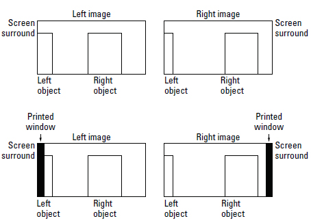
Figure 5.7 Floating or virtual windows. Top stereo pair is without floating windows, the bottom with. The rectangle labeled “right object” is not occluded by the vertical edges of the surround, whereas the left rectangle, which has off-screen negative parallax, is occluded by the left edge of the surround. A conflict of cues is avoided by adding the black bands to produce a new vertical surround with negative parallax to match that of the occluded object. If viewers can free-view stereo they can see the problem and the cure. (Image courtesy of Lenny Lipton.)
The technique of floating windows harmonizes with the esthetic of the current stereoscopic cinema. In reaction to prior practice, modern stereographers, for the most part, use a modulated approach to depth effects and off-screen effects judiciously. Floating windows, by expanding the usable parallax budget into the audience space, tend to reduce off-screen effects. But when needed the windows can be withdrawn or adjusted to allow for off-screened effects. In many shows floating windows are changed from shot to shot, or the values of the effect are different from one side of the screen to the other, or on occasion, the windows tilt, and they can be moved during a shot. Floating windows work if the audience doesn’t notice them.
Fix It in Post
While the phrase “fix it in post” sounds like an old cliché, for stereo 3D it is a daily routine. For more than half a century cinematographers baked in the look on film they were trying to achieve with the camera. With the advent of the digital intermediate (DI) step or shooting with digital, the trend is now to capture raw or neutral data so that corrections and the look of the film to be determined can be created in post. Specifically this takes place in color timing, and the equivalent for 3D, stereo timing, is emerging.
Two major products have been released in the past 2 years, one from Quantel, the Pablo, and one from Avid. The Pablo allows camera errors to be fixed and it also allows the zero parallax setting to be adjusted, most probably as a step after the film is cut. The Avid off-line editor treats stereo the way it treats color. Films are cut before they are color timed but Avid lets the editor see color—albeit untimed. The same thing is true for stereo. The editor will see the untimed stereo effect, probably on a TI DLP RPTV using shuttering eyewear. The Avid uses the above and below (also called the over and under) format to organize the left and right images.
Arguments have arisen about whether raw or neutral digital data should be used for controlling zero parallax in post. When cutting shots together, there is the ability to figure out how the shot should play with respect to the others. Visualizing how a stereo image looks is difficult to do at the time of photography and visualizing how one shot will work with adjacent shots in post is even more daunting. For one thing the monocular cues play a large part in how deep the image will look and it is hard to visualize how they weight the stereo cue.
It would also be a good thing to be able to control, for live action, the interaxial (and, hence, the strength of the stereo depth effect) in post as well as the zero parallax setting. While the technology to do this could be developed, as of early 2010 there was no product on the market that does the job of allowing the depth strength of a shot to be dialed in.
STEREOSCOPIC DESIGN
Sean Phillips
“If people were meant to see 3D movies they would have been born with two eyes.”
—Apocryphal quote attributed to Sam Goldwyn
The Emerging Grammar of 3D
Digital projection has, for the first time, made flawless mass 3D presentations possible, and digital imaging tools now give film-makers sufficient control over the stereo image. The future promises complete control and pixel-perfect stereo accuracy. At this very moment, a grammar for the creative use of 3D in motion pictures is being invented. Each new 3D film is a step forward and a lesson. For 3D to be a meaningful part of the grammar of film, however, it has to contribute to a film’s ability to tell a visual story that engages the emotions of an audience.
Creative Use of Depth
Analogies to Color and Visual Design
An audience doesn’t consciously think about color or space when watching a story told on the screen. Instead, the response to it is immediate and emotional. Conversely, a typical story involves conscious attention by the viewer and is told through actors—human, animal, or virtual—that engage the audience with empathy and stir their emotions through conflict. The visual elements of a film usually overlie this drama. Used well, the visual design of a film can give it a style and, more importantly, a unique emotional feeling that augments the underlying story. Today 3D is a novelty and any form of it looks interesting to audiences, which sells tickets. The same was true when Technicolor first came out, but the industry was quick to put it into service to enhance a film’s visual design. Stereo design will follow a similar pathway but, because it is so new technologically, it doesn’t have as much history as color did in other media like painting and photography. The important creative question to answer is “What does 3D add to a film?”
Stereo adds a new level to a film’s visual design. In its purest form 3D gives the viewer a palpable connection to the images of a film. An actor looks real and alive. It is intimate, sensual, tactile, and immersive. In its raw form 3D is not subtle and it is not ambiguous, but with good design both of these qualities can be introduced as needed and used with great precision. Like the saturation of a color image, a stereo image can be very dimensional or have the stereo cues completely removed by the taking cameras. The stereo effect can also be exaggerated or twisted to defy reality. The control obtained over real and virtual stereo cinematography is such that there are very few aesthetics of a 2D film that cannot be part of a 3D film as well.
A 3D movie expands a filmmaker’s working space in front of and behind the screen. In addition to screen right and screen left, there is now a stereo window, dividing stereo space into theater space and screen space.
The Stereo Window
The stereo window was born out of the need to make a stereo image work within a photographic composition. When an object in a 3D movie appears closer to the viewer than the physical space of the theater screen, there is an inherent visual conflict when that object breaks the edge of frame. This problem can happen on the left or right sides of the screen, but it is not so much of an issue on the top or bottom of the screen. The reason for this is simple: The left and right eyes are separated horizontally, so the left and right sides of the screen are where stereo cues are perceived. The top and bottom of the screen are, by contrast, stereoscopically ambiguous.
To solve this problem, the stereo window was created, which is a construct that stereographers use to minimize depth conflicts at the left and right frame edges. The interocular2 is adjusted so that nothing in the background has a divergent offset on the typical movie screen of more than 2.5 inches as measured on the screen. This keeps the viewer’s eyes from diverging or going “walleyed” when watching the film. Since screen sizes vary from 20 to 40 feet or more, a safe divergent offset value used for widely released 3D films is 1% of the screen width. That means that the positive stereo parallax seen behind the screen plane shouldn’t exceed 1% of the screen width. That would be 20 pixels on a 2k image. There are times when this rule can be exceeded, especially when using soft backgrounds, but care must be taken. (Please refer to the Stereoscopic Window section later in this chapter for a detailed in-depth discussion of the stereo window.)
Theater Space
Things that appear in front of the stereo window are said to be, not surprisingly, in theater space or off-screen. The stereo offsets in front of the screen are called negative parallax, because the distances are getting closer to the viewer. For shots of actors it is usually acceptable to break the bottom of the screen in theater space but not the top. It is good practice to keep the actor’s head from breaking the top of the frame and to keep people and objects in theater space from breaking the left or right side of the frame—unless it happens very quickly. Actors can make quick entrances and exits in theater space, but slow entrances and exits are best avoided. Those are the major don’ts of theater space.
Theater space is an area where the most immersive and palpable forms of 3D can be created, and it is vastly underutilized because of the time and effort required to properly design its use. A traditional dialogue scene with reverses and even over-the-shoulder shots can be played in theater space with the right design—but this requires all departments to work together with a common vision. Playing a scene like this at, or behind, the screen plane is easier, safer for editorial, and in many cases appropriate, but in as many cases it is not using the 3D medium to its fullest.
Screen Space
Screen space is all the remaining stereo space the audience can see behind the screen, or stereo window. This space is often referred to as having positive parallax. Objects in this space can move with no restriction on traditional framing. Actors can enter and exit any time they want as long as they are at, or behind, the point of convergence. Cinematographers may frame traditionally in screen space, and even very high contrast lighting is unlikely to cause ghosting issues.
Less is More
The stereoscopic depth effect is very powerful, but it is very important to use it in moderation. If a scene is played at reduced interoculars, the next scene, if played at wider interoculars, will appear much richer in depth. This is simple contrast, just like light and dark and complementary colors, and it can be just as effective.
Practical Storytelling in 3D: Two Extremes
One director wanted to shoot his 3D film the same way as he would shoot a 2D film, but this approach does not make very good use of the 3D medium’s capabilities. A blanket direction to the 3D team was “Just give it as much depth as possible.” This kind of director is going to produce a very unsatisfying 3D project, thus mitigating the very reason for doing it in 3D in the first place.
At the other extreme, a different director used a camera that had only convergence control. The lenses were fixed at 63mm (2.5 inches) apart. Not being able to reduce the interocular is a severe constraint in 3D, but the director was eager to stage and design the film to work best for 3D. Tests were shot where the stereo was pushed far beyond its limits. This was very important because it allowed the director to see what worked and didn’t work in 3D. By seeing those boundaries a common frame of reference was created, allowing the 3D team to design the film’s 3D to its creative limits. Shots of actors on green screen were layered in order to build up depth of field and work within the stereo budget. Every shot was staged with 3D in mind, and in the end the film was far more effective in stereo than the first film discussed because of its design—despite a much smaller budget and the serious working constraint of a fixed interocular.
The stereo design should be discussed between the director, DP, and stereographer in pre-production because it will become the 3D road map for the film. Which scenes are played heavily in theater space, at the screen plane, or in screen space? Where are unique or complex 3D effects needed? This dialogue also facilitates choosing the best 3D capture systems for the particular film.
Previsualization
Three-dimensional photography can be previsualized in CG with extreme accuracy. This accuracy can be used to predetermine at what interocular and convergence settings a visual effects–laden scene will be shot. Stereoscopic previsualizations are most helpful when doing greenscreen work with actors who will interact with CG characters. When actors are photographed on green screen, the interocular distance is baked in to the scene. So if there is only a vague idea of what’s to happen in the CG portion of the scene, there is good chance that the interocular chosen on set could prove to be wrong. By previsualizing the CG characters’ motion in stereo space, the best interocular setting can be predetermined for the live action greenscreen photography. One important aspect to previsualization in 3D is that the virtual world should use real-world units (feet, inches, meters, etc.) to define that world. This makes everything previsualized completely accessible to the stereography, camera, and art departments in meaningful units, hence enabling successful execution of principal photography. When virtual units are arbitrary, simple errors that can be expensive or impossible to fix later are difficult to spot.
Avoiding Painful 3D
The 3D process can actually cause physical pain if used incorrectly. Because of this there are a lot of noncreative issues that have to be respected before 3D can be used aesthetically.
Painful 3D is caused by an unacceptable difference between the left and right eye images. In a properly aligned 3D image pair, a slight left-right shift in the perspective of the stereo images should only be visible if toggling between them on a workstation or digital intermediate suite. This horizontal shift varies with an object’s distance from camera, but is usually not more than 4% of the image width and often much less.
Vertical misalignment, where one image is set higher or lower in the frame compared to the other eye, is a very disturbing thing to see in 3D. However, this usually can be eliminated in post by shifting the images up and down in relation to each other until they appear aligned.
Color hue, color saturation, image sharpness, contrast, brightness, and image geometry should all be consistent between the image pairs. If not, they need to be carefully balanced in post. Stereo errors in photography can have catastrophic results. For example, shooting with too wide an interocular can bake in a stereo offset that is unwatchable in the theater. It might have looked acceptable on a little 3D screen, but a big theater screen changes everything.
Additionally, improper stereo synchronization of any of the camera functions—frame rates, shutters, focus, iris, and zoom controls—can also doom a shot. And keep in mind that these are just the basics. With all of these potential issues, it is not surprising that stereo cinematography has been a slow, laborious process where most of the effort is directed at avoiding humiliation rather than furthering the creative use of 3D. Digital capture and the digital intermediate process are now typically used on most projects to ensure that the image streams are well aligned and presentable.
The Aesthetic of Scale
In a traditional film the perception of the scale of an object is defined by 2D cues such as texture, aerial perspective, depth of field, and proximity to and occlusion by other objects. In its raw form 3D wants to assign scale to everything. It becomes very specific and unambiguous. On a small screen, or in combination with a wide interocular, it will create the effect of apparent miniaturization. This effect is usually unwanted on people—unless the film is about miniature people.
One of the great charms of going to the movies has been the way the screen makes characters look larger than life—not smaller. This is a design aesthetic that is desired in 3D movies as well. Audiences are very comfortable watching 3D movies when actors appear, in the back row, normal in scale or larger. Audiences feel uncomfortable when people look miniaturized in 3D movies. The acceptance of larger than life appearances of actors in the cinema has made apparent gigantism in 3D movies something that audiences do not perceive. An actor can have an apparent scale of 22 feet in a 3D cinema and it doesn’t look unnatural unless there is a relative error in scale. For example, if a 12-foot actor is standing next to a car whose apparent scale is normal, he will look like a giant relative to the car. The process of creating a stereo window generally tends to increase the apparent scale of the subject because it narrows the interocular to reduce divergence and it pushes the subject away from the camera to put him at or behind the stereo window. It is an open question whether audiences will get very picky about scale as their stereo sophistication grows. However, it is a safe bet that people will still want to see actors who appear larger than life.
Lens Choices
In general, you should shoot with wider lenses in 3D. A wide lens expands space in a way that is pleasing to the eye—especially for architectural interiors. Wider lenses also have more depth of field, which is especially helpful for foreground objects. When moving in for close-ups on actors, it is better to get physically closer and use a wider lens. For example, if an 85mm lens would ordinarily be used for a close single, a 50mm lens would probably work better in 3D. Longer lenses compress space in ways that are more subtle and flattering for close-ups in 2D than 3D. Long telephoto lenses compress space even more, and the effect in 3D is like looking through a pair of binoculars at a series of flat cutouts with exaggerated expanses of space in between them. That might be the right look for some films, but not most. This “cardboard cutout” effect can be compensated for to a degree with wider interoculars and staging that carefully places objects in space—within very strict limits.
Fish-eye lenses have a unique look and can work surprisingly well in 3D, but only for an occasional shot as the vertical alignment drifts at the edges of frame. Many minutes of looking at fish-eye shots will create eyestrain. A side benefit is that because fish-eye lens designs are compact and have an ultra-wide field of view, they can be used in very tight spaces and the fish-eye distortion can be corrected in post. When the distortion is removed, they behave like an ultrawide spherical lens in 3D. Ultra-wide lenses, and especially fish-eye lenses with 180 degree fields of view, translate left-right stereo parallax at the center into z-axis shifts toward the edges of the frame, minimizing the 3D effect.
A good rule of thumb is that 3D needs a lot of depth of field, and that rule is true most of the time—but not all of the time. In many instances a narrow depth of field is highly effective and can be used to make the depth effect ambiguous when creatively desired. Another rule is that if there is something that needs to be looked at in a shot that something should be in focus. They eye always goes to the person or object that is in focus.
Cutting for 3D
The stereo space of a film needs to flow through the edit just like the motions of actors, angles of cameras, and progress of the story. Being able to preview the edit in 3D in the edit bay is essential. It is also imperative to review the full edit on a theatricalsized screen with the filmmakers sitting at the range of seats that resemble a normal cinema. A 3D edit isn’t done until it can play to all of the seats in the house.
It has often been said that 3D films have to be paced more slowly because of the time it takes to accommodate 3D images. It is certainly true that big 3D in-theater effects need to be given sufficient time to read to the audience and then withdrawn before cutting to the next shot. In general, however, a 3D film can work at just about any pace if it has been properly designed. The challenge is creating a flowing continuity of space for the eye to follow. If the stereo depth flows across the edits, it is possible to cut a scene very quickly.
Over the course of a scene, the intercutting of 3D shots creates a spatial relationship between characters. If the space between characters is too great, it will appear unnatural, as will jumps in the space of characters. Most of these issues are solved in photography by keeping the intercut action close to the stereo window. Oftentimes the director will want to move beyond this convention and play action more in theater space, but the scene must be carefully designed and essentially edited in advance if it is to be successful.
When the space of two shots is very different and those shots are juxtaposed, a stereo jump cut is created. The classic example is cutting from a wide scenic vista to a single of an actor well out into theater space. A cut happens instantaneously, but the viewer’s eyes take time to accommodate a stereo image that is on a different plane in space. Eyes are relaxed and nearly parallel when they look at objects far away in space, easily fusing two almost identical images into about the same place on each eye’s retina. The amount of eye cross tells the brain how close things are—the closer things are, the more the eyes have to cross. Cutting from deep space to close space instantly makes the eyes try to cross and takes the audience out of the story. Conversely, it is far easier to cut from something close in space to something far away as the eyes are actually relaxing across the cut.
Floating Windows
The stereo window does not always have to stay at the theater’s screen plane, and that is where floating windows come into play. Imagine if the black masking around the frame had a stereo offset all its own. The floating window itself could then be placed deeper in space than the real screen or, more commonly, closer. Floating windows are part of the domain of editorial because they are almost always used in post to fit a stereo image whose depth budget has exceeded the normal screen plane. It is also a powerful tool for converting films shot in other formats with large depth budgets like IMAX 3D for presentation in RealD theaters. For a more in-depth discussion of these topics, please refer to the previous section, How 3D Works.
Designing for Multiple Release Formats
The technology of 3D is constantly evolving, and it needs to. At present, most 3D camera systems look like science projects. As high-resolution motion picture cameras move toward lower and lower price points, and as integrated electronics become available, the stereo camera systems will become much more “set friendly.” Presentation technology is also evolving quickly. 3D screen sizes are currently limited by projector brightness, but new generations of projectors, and multiple projector tiling based on automated machine vision, are already entering the special venue field and will soon be scalable to a mass audience. Because of constant change one can never be sure where a 3D film will show or under what conditions. A 3D feature film will appear in RealD and Dolby theaters, possibly in IMAX 3D, or on the Internet. And the truth is that 3D cannot be shot in a way that works perfectly for all formats. All that can be done is to shoot and design a film for its primary market. If it is a feature, shoot it for a RealD-sized screen. If it goes to IMAX, it will need to be reconverged to fit into that format.
Immersion-Based versus Convergence-Based Stereo
Traditionally 3D in motion pictures has been called convergence based, meaning it uses convergence to place the scene within a stereo window, as discussed so far. There is another way of designing 3D films that emerges from a construct known as the orthostereo condition. To create this condition, one shoots with a lens that has the same angular field of view that the viewer’s eyes have to the theater screen. The two cameras are also the same distance apart as the viewer’s eyes (about 63mm or 2.5 inches) and the cameras are completely parallel, meaning that their convergence is set to infinity, as are the projectors. What this condition creates is an exact, one-to-one re-creation of reality in the stereo space of the theater.
The problem with using orthostereo has always been that anything in the image closer than the screen that is cut off by the edge of the frame collapses in depth. This is why the convergence-based stereo window was devised in the first place. But there is a way to get around this problem.
3D IMAX and Giant Screen Venues
Something very interesting happens on a movie screen when the audience sits within two-thirds of a screen width away from it: The image becomes completely immersive. In other words, the audience no longer thinks about the edges of the frame, there is no “stereo window,” and the image space can be designed to float anywhere between the eyes and infinity. This is the essence of immersion-based 3D. It demands a huge shift in thinking away from traditional frame-based filmmaking, where convergence has always been used to make 3D fit the traditional 2D compositional window. However, when viewing from two-thirds of a screen width away from a typical movie screen, the image is so magnified that its quality is extremely poor. What has made immersion-based 3D possible is the higher resolution (about 8k) of film formats like IMAX and the giant screens on which they are displayed.3
A convergence-based projection system, whether it is one or two projectors, always strives to align a grid pattern from each eye into a single identical grid pattern on the screen when viewed without 3D glasses. In an immersive system, like IMAX 3D, the grid image from the left and right projected images are offset exactly 63mm, or 2.5 inches, on the screen—the average distance between human eyes. Although 63mm, or 2.5 inches, may not seem like a lot, especially on an 80-foot-wide IMAX 3D screen, that separation is essential because it makes objects appearing at near infinity to the camera appear at near infinity to the viewers in the theater.
An IMAX 3D film is shot in a very different way from a traditional, convergence-based film. Because there is no stereo window, almost everything is staged in theater space. This is a huge break, not just from traditional 3D but also from traditional frame-based filmmaking. Scenes need to be essentially pre-edited when they are shot because a continuity of space needs to be maintained independent of a stereo window.
There is no question that the future of theatrical motion pictures is written on bigger screens. As large HD screens fill homes, the public cinema has to offer something bigger, better, and more immersive. Already theater chains are adding 4k digital screens and larger digital screens are filled as soon as brighter projectors are available. The push for larger theatrical screens is inevitable and will make the possibility of mass distribution of immersive 3D a reality.
VIRTUAL 3D PHOTOGRAPHY
Rob Engle
Virtual 3D Photography Defined
The current renaissance in stereoscopic filmmaking can be closely attributed to the use of digital techniques both for production and exhibition. While digital techniques have revolutionized the acquisition of moving pictures in the physical world, no technology has more profoundly impacted stereoscopic content creation than computer graphics. The use of 3D digital techniques to build a stereoscopic image pair is called virtual 3D photography. CG features are the best example of virtual 3D photography with numerous examples driving the state of the art in 3D filmmaking. These same techniques have been shown to create high-quality 2D-to-3D conversions. This is in contrast to many of the 2D compositing (image-based) techniques that are used for 2D-to-3D conversion of material in which a virtual world, representing a physical world, is never built. By creating a virtual stereoscopic camera and placing it into a scene, one is able to simulate the effect of actually photographing the scene in stereo, producing the highest quality images while gaining a tremendous degree of flexibility in creating the final stereo pair.
Pros and Cons of Virtual 3D Photography
One of the chief advantages of using both image-based digital techniques and virtual 3D photography is the ability to create so-called “perfect” 3D. While the human visual system is very flexible to a wide variety of differences between the images seen by the left and right eye, any differences other than horizontal parallax can lead to fatigue when extreme enough or viewed for an extended period of time. By not being bound by the limitations of physical optical systems, it is relatively straightforward to create stereo pairs with only horizontal parallax. Additionally, by its very nature the post-production process allows the stereographer the flexibility to review the results of his work in the context of the film’s cut, tuning individual shots and cuts to provide the highest quality 3D effect. In many cases this tuning might involve matching the depth of the primary subject matter from shot to shot to minimize the impact on the viewers’ having to adjust their eyes’ vergence. In other cases the stereographer may be making creative choices about the overall depth of a shot or to what extent the subject matter should extend in or out of theater space.
Another benefit of using a virtual camera to render a stereo image is that it is possible to create 3D compositions with very deep focus. In the physical world, assuming the viewer has good vision, everything will be in sharp focus. This means the technique of using a narrow depth of field, which has been commonly practiced in planar cinema, runs counter to creating a truly deep 3D experience. The virtual camera with its idealized “pinhole” properties allows the stereographer complete control over depth of field. While many cinematographers would use a narrow depth of field to direct the viewer’s gaze, the 3D cinema is a different medium and benefits from different techniques. If you are trying to create a truly immersive 3D experience, it is generally better to use lighting, movement, and deliberate 3D staging to direct the viewer rather than to rely on a narrow depth of field.
The single biggest disadvantage of virtual 3D photography is that all objects must be modeled and exist in proper scale and location in the virtual world. Objects that do not adhere to this requirement will require special handling and, in the worst case, may need to be converted from 2D to 3D and then integrated into renders of the virtual world.
Multiple Camera Rigs
A technique that is somewhat unique to virtual 3D photography and has been applied on numerous CG features is that of photographing a virtual scene using multiple stereoscopic camera pairs. By isolating individual objects or characters in a scene and tuning the stereo parameters on a per-object basis, you can achieve a higher degree of control over the use of the parallax budget for a shot.
Oftentimes, many of the same effects of multiple-camera rigs can be achieved by judicious selection of lens focal length and object distances. However, the multiple-camera rig technique enables a significantly greater degree of flexibility and allows one to compress and expand the 3D effect in ways that are very difficult to achieve by any other means. For example, with normal stereoscopic photography, a foreground object will have more internal dimension (roundness) than objects that are farther from the camera. In the case of an over-the-shoulder shot, it may be desirable to compress the roundness of the foreground and minimize the distance to the primary subject while enhancing the roundness of the subject.

Figure 5.8 In this shot the apparent roundness of the main character as well as the other characters was manipulated using the multiple-camera rig technique for Beowulf (2007). (Image courtesy of Paramount Pictures. BEOWULF © Shangri-La Entertainment, LLC and Paramount Pictures Corporation. Licensed By: Warner Bros. Entertainment Inc. All Rights Reserved.)
If a scene has multiple characters, it can be helpful to subtly compress the space between the characters while giving them more roundness to minimize the cardboard effect. Selectively applying roundness to individual objects can also be used to heighten the emotional impact of the film. In Robert Zemeckis’ performance capture epic, Beowulf (2007), individual characters were often isolated and given extra roundness when they were in a position of power while their roundness was minimized when they were in relatively weaker positions. In addition to using this technique as a creative tool, it is also possible to use multiple-camera rigs to correct technical problems such as incorrect eye lines or unusual character scaling that would normally require sending a shot back to animation.
Note that the multiple-camera rig technique will often not work when applied to separate objects whose interface is visible in the shot. For example, it would be difficult to apply two separate stereo settings for a character and the surface on which it is standing because it is important that the character still appear to be on the surface. If the character is standing still or one is using a results-driven camera rig, it may be easier to make this example work, but, in general, these kinds of shots don’t benefit from this technique anyway. Additionally, while this technique can be used for live-action photography with the use of greenscreen matting to isolate elements, it is somewhat impractical to implement on a large scale.

Figure 5.9 In this example from Open Season (2006) the animator used forced perspective to get the righthand character to feel smaller (placing her farther away from the camera). A multiple-camera rig was used to correct the characters’ eye lines without changing their scale. (Image © 2006 Sony Pictures Animation Inc. All rights reserved.)
Creating a finished multiple-camera-rig shot involves rendering each group of objects through their associated camera pairs and compositing the renders, taking into account the depth sorting order. Because it is very easy to create unnatural depth effects and interfere with the viewer’s sense of scale using this technique, it is very important to visualize the final result as early as possible. In many production environments custom viewing software is required in the layout and animation package to allow for live preview of multiple-camera-rig shots since most animation packages do not have native support for this feature.
The 3D Camera Rig
When implementing the virtual 3D camera rig, three primary strategies are used most commonly.
When mixing virtual photography and practical photography, it is very important for the two virtual cameras to match the plate photography as accurately as possible. Since physical cameras rarely are perfectly aligned with matching focal lengths, the matchmoved cameras cannot simply be driven by an interaxial spacing and convergence value. They must be allowed to freely translate and rotate in all dimensions relative to each other. As a consequence, this style of rig imposes the fewest constraints on the left and right cameras, but also gives the stereographer the least intuitive controls.
The “direct” style of rig constrains left and right cameras to each other such that only horizontal offsets can be obtained and are driven by the interaxial spacing and convergence parameters. This rig is probably the simplest to implement and offers the stereographer a set of controls with the closest parallels to real-world stereoscopic cameras.
Layered on top of the direct rig, it is also possible to implement a “results-driven” rig that allows the stereographer to adjust controls such as on-screen parallax, an object’s perceived distance from the viewer, and object roundness. This type of rig would normally have locators or measuring planes that can be placed in the scene at a near and far location along with specifications for the desired apparent distances or expected parallax values. A results-driven rig that allows control based on the viewer’s perceived distances will need to make assumptions about the distance from the screen at which the viewer is sitting as well as the size of the screen.
Implementing Convergence
When building a physical stereoscopic camera it is common practice to implement convergence by rotating the individual cameras (typically only one camera actually rotates) toward each other. On long focal lengths or when the amount of rotation is small, this technique works quite well. In other circumstances, however, it is possible to create a fair amount of vertical keystoning as a result of this rotation. Since the keystone effect is different on each side of the image (the left eye will be taller on the left side than on the right), this technique can cause vertical parallax, making the images difficult to fuse when viewed as a stereo pair.

Figure 5.10 On the left a stereo pair has been converged using toe-in of the cameras. On the right the stereo pair has been converged using horizontal image translation.
In contrast, the virtual stereoscopic camera is typically built such that, rather than rotating the left and right eye cameras, the film planes of each camera are shifted horizontally. By simply shifting the individual eyes, no keystoning occurs and a near “perfect” stereo pair is produced. This is a direct result of keeping the individual eye film planes parallel to each other.
If desired, it is possible to simulate this technique using practical photography. On the stop-motion animated film Coraline (2009), the filmmakers used a single camera on a motion control base that would move the camera left and right, keeping the film backs parallel. By using a large imaging array (wider than the film’s release format), it was possible to converge the cameras as a digital post move. Additionally, it is possible to build a stereo camera with a tilt-shift lens or film back or to embed a wide imaging chip in the camera.
Whatever technique is ultimately used to implement convergence in the virtual camera rig, it is important for the entire camera model (including convergence) to match the physical camera rig in the event of integrating CG elements with real-world photographed plates. This requirement may limit one’s options on a mixed live-action/CG production.
Manipulating the Screen Surround
Floating Windows
When the composition of a shot is such that objects in the foreground intersect the left and right edges of the screen, a phenomenon known as the paradoxical window effect comes into play. Objects that appear in depth to be closer than the edge of the frame they intersect create confusion for the viewer. Suppose a close object intersects the right side of the frame. In this situation, without some form of correction, the viewer is able to see more of the object in the right eye than in the left. This experience runs counter to the normal experience of looking through a window in which the left eye would be able to see more than the right. A very simple solution to this problem was employed by Raymond and Nigel Spottiswoode in the early 1950s. They moved the edge of the frame closer to the viewer by imprinting a black band on the side of the frame in the appropriate eye. The black band effectively hides the portion of the image that wouldn’t be visible if looking through a window.
While use of this technique allows one to avoid the visual paradox created by the edges of the frame, it also can be quite useful as a creative tool and to subtly convey the context of a shot as well. By moving the window closer to the audience than would be needed simply to correct the screen window paradox, one could convey, for example, a given shot as a character’s point of view or make a flat, far-away shot feel deeper. This floating window technique is especially useful for smaller screen presentations in which the screen edges are a distinct part of viewing the film.
It is especially important when using this technique to make sure the theater does not allow the sides of the image to overlap the theatrical masking. If the theater introduces its own masking to the image, the effect of the floating window will be lost. It is now common practice for films using a floating window to include a “guard band” of black on either side of the frame and to include a reference framing chart to aid the projectionist in properly framing the film.

Figure 5.11 An example framing chart from the film G-Force (2009). (Image courtesy © 2009 Disney Enterprises, Inc. All rights reserved.)
Breaking the Mask
The very purpose of the floating window technique is to ensure that objects which cross the edge of the frame do not appear to conflict with the frame itself. Another technique, rather than forcing the objects which cross the edge to appear behind the frame, is to matte them such that they appear to be in front of the masking. A black border can be introduced on any side of the image with select foreground parts of the composition allowed to extend over the border. The resulting effect reinforces the audience’s sense that these objects extend into theater space. On G-Force (2009) this technique was employed heavily to allow objects to appear to be farther into theater space than they really were. By masking objects to appear in theater space but limiting their negative parallax to near screen level, the film was made more dynamic without sacrificing audience visual comfort. One of the dangers of this technique (common to many theater-space effects) is that it can distract the audience from the narrative flow of the film if used at the wrong time. Limiting the use of the effect to action scenes often works best, and subtler uses, such as placing spark and debris elements over the mask, will keep the audience involved in the film.

Figure 5.12 Breaking the mask as illustrated in G-Force (2009). Note that the shards of glass fall both in front of and behind the black masking helping to fix the depth of the mask itself. (Image courtesy © 2009 Disney Enterprises, Inc. All rights reserved.)
Note that neither of the above two techniques for treating the screen surround are truly limited to use in films created with virtual 3D photography. It is relatively straightforward to implement a floating window in any digital release, and post-production tools for their creation continue to be refined. The breaking-the-mask technique is probably easiest to implement when all of the elements are easily isolated (as in a CG film) but wouldn’t be out of the question in films created using other methods. (For a more complete discussion of stereo windows, see the Stereoscopic Window section later in this chapter.)
Special Cases for Virtual 3D Photography
One of the primary rules that cannot be broken when creating virtual stereoscopic photography is that you cannot “cheat” 3D. Artists who are well versed with creation of planar CG features and live-action visual effects films are used to a variety of 2D shortcuts to achieve convincing and high-quality imagery. Many of these shortcuts do not lend themselves well to 3D filmmaking. For example, it is important that renders use proper holdouts and proper shadow casting objects. In 2D filmmaking, it is common practice for simple effects elements (e.g., smoke or sparks) to be rendered without any object holdouts and then composited into the scene. When translated to 3D, however, without proper holdouts, these effects elements will now intersect objects because the depth of the element may be behind something but not held out by the object.
Another common practice is to use compositing techniques (rotoscoped shapes or drop shadows) to enhance a shadow or color correct an element. If the 2D shape being used to correct the effect is not properly mapped onto the surface being manipulated, the shape may appear to float in 3D space.
Reflections and transparency are another special case because they must be rerendered in order to get a convincing effect. If one were to use a 2D technique (offsets or image warping) on an element with obvious reflections or transparency, the effects would appear to stick to the object surface rather than having the expected look. For a fully CG film, it is usually sufficient to simply rerender objects that are highly reflective or transparent. In the case of a 2D-to-3D conversion (whether using 2D techniques or virtual 3D photography), it is important to isolate the surface of the reflective object from the image in the reflection.
Last, note that one of the biggest “cheats” in filmmaking is the use of matte paintings to create entire backgrounds (and sometimes foregrounds) in 2D rather than having to actually model them. Any time a 2D matte painting is used (unless it is in the extreme distance), some 2D-to-3D conversion work is likely to be needed to integrate it into the rest of the scene.
2D TO 3D CONVERSION
Matt DeJohn, Anthony Shafer
The recent resurgence of stereoscopic 3D (stereo) motion pictures means that the visual effects artist of today can be called on to create a new level of visuals, an area of expertise that was previously handled in obscurity. The intimacy with which the audience participates in a stereoscopic picture is an important aspect of the experience and, therefore, for projects not shot in 3D, the conversion. The stereographer4 must understand the director’s overall intent with the film, as well as the contextual composition of each shot, because this information will alter the amount of depth and style used in the conversion process.
The 2D-to-3D conversion process generates alternate perspectives from a 2D image. When these images are appropriately displayed, the viewer fuses5 the two images into one to create a stereoscopic effect. A 2D-to-3D conversion can be done with any type of footage, including live-action footage, or animation. Live-action 2D-to-3D conversion is uniquely different from live-action stereo camera capture in that the entire stereoscopic effect is created in post-production. This allows live-action production to capture footage with typical equipment in a typical time frame. A positive aspect of the post-production conversion is that the depth can be significantly altered to match the edit, the director’s developing artistic desires, or any other reason. The concession for these positive aspects is longer post-production time. Performing conversion simultaneously with other post-production processes can mitigate this, but some additional post-production time should be allowed for.
Depth Creation Preparation
Before creating a stereoscopic pair from a monocular image, the image must be analyzed to identify depth cues to help determine the shape and depth of the original image. The human visual system derives perceived depth using both physiological and psychological cues. Retinal image size, linear perspective, texture gradient, overlapping, motion parallax, aerial perspective, shading, and shadows can all be used to help determine the depth of an image and the shape of an object. Individually, each cue provides an indication to the original depth and shape of an object. Identifying as many cues as possible will provide a more accurate representation of the original image depth.
Visual Analysis of 2D Depth Cues
A 2D depth cue is the visual perception of depth without an alternate perspective. In the 2D-to-3D conversion world they are referred to as implicit depth cues, as they already exist in the original 2D image. Some of the most important implicit depth cues are occlusion,6 relative size, height in visual field, motion perspective, aerial perspective, and depth of field (see Figure 5.13).

Figure 5.13 Implicit 2D depth cues. (Image courtesy of Matthew DeJohn.)
Occlusion indicates general object ordering implied by overlapping objects. Relative size indicates depth based from the size relationship of objects in the scene. Height in the visual field indicates depth because humans see the world from an elevated perspective in relation to the ground. Given this fact, the bases of distant objects appear higher in one’s visual field than nearer objects. (The example in Figure 5.13 specifically shows this relationship with no consideration to the relative size difference that would be present.) Motion perspective indicates depth based on the distance an object travels in one’s visual field during its own movement or the movement of one’s point of view, such as during a crane, dolly, or trucking shot. Aerial perspective indicates depth through a loss of detail and contrast present in distant objects. This is caused by the amount of atmosphere between the viewer and the subject; therefore, in space there would be no aerial perspective depth cue.
One needs to understand these implicit depth cues in order to accurately analyze an image for conversion. The artist’s explicit choices of convergence and binocular disparity must be consistent with, or at least not conflict with, the implicit depth cues. For example, if two men, who in reality are the same height, appear to be different sizes in a 2D image, there needs to be sufficient separation in Z-space7 to justify their size difference in the image. Also, the degree of these implicit depth cues helps indicate the amount of volume and separation necessary to properly convert the image. Take the example of the two men again: The greater the apparent size difference between them on the 2D image, the more separation is needed to support that implicit depth cue.
It is important to note that the more depth that is built into the scene, the more accurate the artist’s analysis of the scene must be because the viewer is more likely to see any disparities between explicit and implicit depth cues. In a sense, the more depth that’s created in a scene, the more definitive the explicit depth choices are.
Main Artistic Stages of 2D-to-3D Conversion
Most successful 2D-to-3D conversion techniques requires three broad artistic phases: element isolation, occluded surface reconstruction, and depth generation. Although some approaches can yield results without these artistic phases, they are not adequate for most shots.
Element Isolation
The goal of element isolation is to define the elements in the image that had substantial physical separation between them in order to offer flexibility when creating the 3D effect. A pen on a desk would not need to be isolated; however, the desk would need to be isolated from the ground. Even if portions of elements connect, such as the desk and the floor, it is often advantageous to isolate them separately. This allows for independent shaping, positioning, and perspective control. It is important to note that this specific approach is more applicable to the pixel displacement workflow (discussed later).
Another way to determine which elements to isolate is by analyzing which elements are not visually connected (see Figure 5.14). This approach is specifically applicable to the re-projection workflow. Consider a medium shot of an actor in a room; even though the audience knows the actor must be standing on the floor, there is not a visible connection with the floor since the framing is on the torso and not revealing the connection. Therefore, the actor can be isolated from the background because he does not exhibit connection to room, specifically the floor, within the frame. Element separation allows more flexibility when creating a realistic 3D effect.

Figure 5.14 Left: Subject visually connected to floor. Right: Subject not visually connected to floor. (Image courtesy of Anthony Shafer.)
Element isolation reveals the necessity for another artistic phase, occluded surface reconstruction. When foreground elements are isolated, that area also indicates the occluded surface that may be revealed by 2D-to-3D conversion. The occluded surface lacks appropriate image data and so may require image reconstruction.
All standard visual effects methods for isolating elements apply to 2D-to-3D conversion. Those methods include rotoscope, manual paint, procedural paint, and procedural keys.
Isolating elements for a 2D-to-3D conversion process can be quite challenging. Artists are required to isolate an element with the same degree of accuracy as would be expected if the shot was properly captured on a green screen. If this level of accuracy is not met, the audience immediately sees the errors. Poor matte creation in 2D-to-3D conversion can actually make a shot look like a bad greenscreen shot even if it never was. Particularly challenging elements to isolate are out-of-focus objects, objects with motion blur, hair, and highly other intricate objects such as trees.
Occluded Surface Reconstruction
A 2D-to-3D conversion creates at least one alternate perspective. This new alternate view commonly reveals new surfaces that were not visible in the original perspective. These revealed surfaces must be filled with accurate image information to complete the 3D effect. This occluded surface reconstruction (OSR) can be achieved by a variety of visual effects methods such as clean plate reconstruction, re-projection, automatic temporal filling, or frame-by-frame paintwork.
The goal when performing any OSR is to maintain consistent textures, motion, grain, color, and luminance between perspectives in order to avoid fusion errors. While that’s easy enough to understand, OSR is generally the least forgiving process. To illustrate this, consider a medium shot of a character shot in front of an ocean. When the additional perspective is created, more ocean is revealed. When reconstructing that surface, the texture of the waves needs to be maintained. This is challenging enough on a single frame, but this texture needs to move in a way consistent with the rest of the ocean. This type of moving texture is difficult to re-create because the human brain is so attuned to how the ripple should progress into the occluded space. Also, in this example, the ever changing color and luminance must be maintained accurately.
Many paint tools (procedural, nonprocedural, and autopaint) can be used for OSR. Autopaint tools generally fall into two categories, temporal-filling8 and pattern matching.9 It is best to attempt to get as far as possible with a temporal-filling algorithm and then move to a pattern-matching algorithm.
Results with automated tools can vary greatly and so manual paint tools (procedural and nonprocedural) are almost always necessary. It is advisable to do as much as possible in a procedural fashion, because paint and/or depth revisions are inevitable. The full range of paint, rig-removal, and matchmoving techniques will need to be used at one point or another during OSR. However, there are a few specific things to keep in mind when painting in stereo. For instance, cloning from a source directly next to the target can cause the viewer to fuse a portion of the background at an unintended position in Z-space. Given this common mistake and others, it is imperative to regularly view one’s work in stereo. In general, all source material should be cloned from the new perspective only. Cloning from the original perspective will potentially neutralize shaping.
Grain management is essential in the OSR process. First and foremost, grain must be consistent in nature between layers regardless of the Z-depth position. Some paint techniques, like matchmoving a single clean plate to fill occluded surfaces, can result in static grain, so grain must be generated to effectively blend this area with areas that have dynamic grain.
A seemingly viable approach would be to de-grain the footage on the front end and then add grain to each perspective after all depth and paintwork is complete. Unfortunately this approach fails because the grain will actually play at screen level like a curtain of grain. In areas of low contrast, the viewer will fuse the grain at screen level and this will likely conflict with the depth of that low-contrast element. Different grain in either eye is not a viable option either. This approach can lead to a discomforting left eye and right eye discrepancy. Grain should map to the surface of the objects in the scene. This will prevent the sheet-of-grain phenomenon and avoid stereo discrepancies.
Depth Generation
The broad artistic depth-generation phase of the process creates one or more additional perspectives, thereby creating a 3D effect. The primary goal when generating depth should be to create a comfortable viewing experience. Even with the inherent benefits of conversion, like perfectly aligned perspectives and perfectly matched exposure, it is possible to cause the viewer discomfort.
Viewers’ interpupillary distance (IPD) needs to be taken into account. Adults have an average IPD of 6.5 cm (2.5 inches) and children ages 6 to 11 have an average IPD of 5.1 cm (2 inches). Along with this knowledge, target screen size should also be considered. If the positive parallax of the image is more than the target audience’s IPD, the viewers’ eyes may diverge or go walleyed. This can cause discomfort, like headaches, especially in children and is likely to take the viewer out of the story because of eyestrain. Since the stereographer will not have control over the final screen widths, with the exception of an IMAX venue, positive parallax values must be averaged. Many digital feature animation studios use a starting positive parallax value of 17 to 20 pixels of separation to represent infinity—based on a 2048 resolution image. Often the final released parallax limit is 11 pixels. These decisions are usually driven by the current average digital 3D screen size. A free application called the Depth Machine can be used to analyze parallax and its implications in terms of perceived depth and screen size. This tool can be found at http://thedimensionalists.com.
Depth continuity is another important factor in creating a comfortable viewing experience. It is essential to be sensitive to how depth transitions from shot to shot in terms of where the focal element is placed in Z-space and what the range of depth is. Range of depth refers to the negative and positive parallax extremes of a shot. In effect, the negative and positive parallax limits built into a shot define the overall depth of the world, commonly known as a pixel parallax budget. If those limits are changed dramatically from one shot to the next, the viewer’s visual system will attempt to accommodate, or reorient itself, to the new visual world, thus potentially missing the film’s intention or performance and may cause eye fatigue. These considerations are not meant to imply that the focal element’s placement in Z-space or that overall depth must be exactly the same from shot to shot. Rather, these decisions should be made consciously in order to provide a comfortable experience that allows the viewer to experience the story.
Continuity of depth is used in 3D feature animation and 3D performance capture to control the volume of the characters throughout the film based on their importance or emotional performance. Depth grading is commonly used to enhance the character performance or the audiences’ participation in the scene. On Meet the Robinsons (2007), the viewing distance to a character equated to the emotional distance of the character, creating an emotional void for the viewer. Likewise, emotionally involved performances were graded closer to the viewer, encroaching on the viewer’s personal space as a way to increase the emotional intensity. Another technique is changing the volume of a character to draw the viewer’s eye. Generally the character volume should be consistent throughout a scene. However, on A Christmas Carol (2009), character volume was occasionally used to determine character importance in the scene. In test screenings, it was revealed that rounder characters were perceived as more important than flatter characters.
A 2D-to-3D conversion has a level of dimensional flexibility challenged only by 3D feature animation and 3D performance capture. This flexibility provides great artistic opportunities. Generally, it is advisable to reinforce the director’s intent. As an example of this, consider two shots, A and B. Shot A is a long-lens shot toward a woman running from a monster that pursues her from behind. Shot B is a medium-lens shot following the woman from behind as she runs down an open trail, with no chance of escape. It is reasonable to infer that the director used a long lens in shot A to “compress,” in a 2D manner, the depth between the woman and the monster. It is also reasonable to infer that shot B was shot with a short lens to make any avenue of escape appear far away. The director’s intent in shot A can be reinforced by creating minimal separation between the woman and the monster, and hence increasing the sense that she will be caught. In shot B the depth of the road can be extended far out into positive parallax, to make her salvation seem impossible to reach.
Another way to capitalize on the flexibility of conversion is to tailor the depth to the edit. If a scene is made of long shots, a viewer has more time to take in the depth. If a scene is made of short cuts, the viewer may have a hard time taking in a shot with a lot of depth. So, for short cuts, it may be advantageous to have a modest depth budget so the viewer can more easily see what is happening. The same theory can be applied to camera motion as well.

Figure 5.15 Perception of scale. (Image courtesy of Matthew DeJohn.)
When choreographing position and volume, it is important to consider the scale these depth choices imply. Think of a wide shot of a 100-foot giant projected where his image is 10 feet tall on the screen. In a 2D environment the viewer is used to seeing this scenario and relies on the implicit 2D depth cues to infer size and distance. Once explicit depth choices are made, it is important to be sensitive to the scale that is implied with the depth choices. Consider a scene where the skyline plays at 2.5 inches positive parallax and the giant plays at the screen level; the giant will likely be perceived as “miniaturized.” The position in Z-space of the giant is definitive and so is his perceived size. Because he is placed at the screen plane and his projected image is only 10 feet tall, he will be perceived as 10 feet tall. If he were placed at about 2.2 inches of positive parallax he would appear to be the correct size. Because the giant’s height on screen is only 10 feet he needs to be positioned beyond the screen, at a point where the 100-foot giant would occupy 10 feet of the viewer’s visual field (Figure 5.15). Generally, issues of accurate scale pertain, to a larger degree, to shots captured with lenses that approximate the human eye (50mm on 35mm film).
Miniaturization tends to be an issue with objects that are larger in reality than they are when projected on the screen. The opposite phenomenon is present with objects that are smaller in reality than they are when projected on the screen, such as a 10-foot-tall projection of a normal person’s face. However, the scale issue present when this person’s face is positioned at the screen level does not seem to be as offensive to viewers.
Another consideration when dealing with the scale position in Z-space is the way it can be used to tell the story. If a director wants to make a person feel more powerful during a dialogue scene made up of neutrally framed medium shots, the director can place the dominant character farther in screen. This will create the sense that this person is larger and perhaps more powerful.
Some other items to consider when generating depth: Is the content a still or a motion clip? A still will require much more detail because it has to be compelling when viewed for long periods, and motion depth cues cannot be leveraged to help sell the 3D effect. A motion clip can more heavily rely on motion depth cues and can have detail commensurate with the length of the clip. The longer the clip, the more detail necessary to sell the effect. What is the effect on occluded surface reconstruction? The amount of depth greatly affects how long occluded surface reconstruction will take. The greater the depth, the more image data that needs to be reconstructed.
Major 2D-to-3D Conversion Workflows
There are as many approaches to extruding an image as there are software packages. The two major approaches to 2D-to-3D conversion are re-projection mapping and pixel displacement. Both of these approaches share the three major artistic phases described earlier: element isolation, occluded surface reconstruction, and depth generation. These two main approaches are distinguished by their depth creation paradigms. Re-projection mapping creates a stereoscopic effect within a virtual 3D environment by projecting images onto geometry from one perspective and rendering from the alternate perspective. Pixel displacement creates a stereoscopic effect by horizontally displacing pixels from a mono image to create one or more alternate perspectives. In both workflows, by using a single perspective as the master view, the alternate view can be synthetically generated and art directed. The choice of methods is determined by software and skill sets. The fundamental result is a pair of image streams that, when presented to the audience, create the sensation of stereoscopic depth.
Special Cases
Reflections, transparencies, motion blur, and deep focus all need special consideration when organizing the depth generation of the image. The approach is rarely easy or straightforward when planning depth extraction of these elements.
Transparencies
Images with transparent surfaces encode two levels of depth, the pixel displacement representing the spatial position of the transparent surface and the pixel displacement of the surfaces behind the transparent surface, both of which are described on a single surface. The complexity of the depth generation depends on the complexity of the surface on the transparent object. If it has intricate details care should be taken to retain the surface integrity. However, the occasion may arise when surfaces may need complete reconstruction. A two-step approach could include a surface reconstruction of both respective surfaces, followed by a traditional visual effects comp to combine the surfaces as originally shot.
Motion blur and deep focus should be handled as a subset of transparent surfaces, where similar depth generation may be applied in the blur boundary overlap between foreground and background surfaces.
Reflections
Mirrored reflections can present an additional challenge, especially if the reflective surface is a narrative or focal point of a shot. Although not initially apparent in a 2D image, a mirrored surface does represent additional depth in the scene and if not taken into account could introduce IPD disparity. Allowances should be made if mirrored surfaces exist while calculating the overall stereo pixel parallax budget. Additionally, all of the depth-generation techniques can be used to shape a reflection or transparency; labor and production costs should be considered because diminishing returns are a potential consequence.
Re-Projection Mapping Method Workflow
The benefit of this approach is that it provides flexibility to manipulate the scene and is a familiar concept for artists to grasp. Organizing elements by volume is essential in this workflow. One method for organizing elements is identifying objects that visibly touch. This is commonly called connective tissue (see Figure 5.14). Objects with connective tissue are tied into the same volumetric space as surrounding objects and cannot be individually graded for depth. Generally the connective tissue is obvious, such as a character embracing another character; obviously both characters are occupying like space and are of similar volume. Any object that interacts with any other object, within the frame, should be considered “touching.” Easily overlooked but equally important are atmospheric effects such as snow, rain, fog, and particulates.
The following represent the basic steps in this process workflow:
1. Matchmove the camera to the plate: The success of the re-projection workflow relies on a proper camera matchmove. Accurate real-world position, rotation, and focal length will allow for properly scaled set geometry and camera interaxial values, which help the stereographer define the depth. If this method is approached like a traditional visual effects shot, it will make the remaining steps less burdensome.
2. Isolate the objects in the plate: A number of industry techniques are used to isolate elements from a plate, the most common of which are rotoscoping, luminance or difference mattes, or a combination of any or all. Use the connective tissue guideline to decide which elements are rotoscoped. It is easy to overthink rotoscoping of articulated mattes. But keep in mind that sometimes loose and rough mattes will suffice; thorough testing should be done prior to investing in articulates. Try to keep objects on similar parallax planes in the same roto spline or at least grouped together. Beware of objects that recede into the distance—they may need additional rotoscoping of overlapping depth, depending on the negative parallax amount.
3. Model low-resolution approximate set and environment geometry: The brain is quite forgiving when presented with a stereo pair, so accurate geometry isn’t always necessary for most depth generation. Simple geometric shapes augmenting depth cues already present will produce a rich and interesting stereoscopic image.
4. Model and rig low-resolution character geometry: Character models can be as rough or as detailed as the scene demands. A small library of generic bipeds is recommended as a base, and higher resolution models can be created when more topological detail is required. Most characters will need simple forward/reverse IK rigs, but keep it simple for the animation team.
5. Match-animate the characters and geometries: Animate characters to the best possible space approximation. Accurate placement of the character in the environment with respect to the camera lens is critical for proper depth generation. Be aware that spatial tricks will be quickly spotted in the stereoscopic medium. It is recommended that the animation team be accurate in the placement of props and characters.
6. Re-project the plate through the left camera: Digital feature animation and most major visual effects houses consider the left camera perspective to be the original plate as shot. By projecting the plate through the left camera and onto the set and character geometries, a virtual set is created that can be rendered by a right camera perspective, thus creating a convincing stereoscopic synthesis of the 2D plate. Additionally, by using an off-axis stereo rig for the right camera, the post-production workload is simplified. It is highly recommended that toe-in camera rigs be avoided for depth generation because they eliminate the flexibility for simple parallax pixel shifting that is afforded by an off-axis pair.
7. Occlusion surface reconstruction:
a. The right eye render will reveal interposition occlusions that are now visible because the right perspective now reveals surfaces that were previously behind foreground objects. To sustain realistic stereo, this missing information must be “painted” back into the plate where the object was moved to create the effect (previously discussed as OSR). A number of paint packages or simple pixel filling algorithms can be used to accomplish this feat, but be forewarned that complex and nonrepeating texture structure such as human faces as well as unique patterns will be difficult, if not impossible, to synthesize via these methods. Laborious frame-by-frame paintwork may be called on to complete a reconstruction effort.
b. Organizing one’s paint will help identify problem areas and alleviate frame management issues. Begin work at the background and work forward, layering each isolated element. Each element will be re-projected onto the geometry and re-rendered as a right eye perspective. Proper organization of layers will help guide a clean composite. Ensure that any object between the camera and the isolated element is painted from the element’s surface; otherwise a “doubling” effect will be experienced when viewed in stereo.
c. If there are multiple objects that interweave or overlap and contain a large distance between them, occlusion reconstruction becomes exponentially more difficult and may require a smaller parallax pixel budget. Proper depth planning at an early stage will result in an easier and possibly less expensive extrusion.
d. Each reconstructed layer should be stored in a fashion that is easy to access by a compositing package. Some complex depth extrusions can generate half a dozen or more layers per eye, so rigid naming conventions are recommended.
8. Rendering the right eye perspective:
a. Render each piece of geometry with its respective clean texture mapped using an off-axis or parallel right eye camera into a new image. This new image should be considered the “stereo pass” for each subsequent isolated element.
b. In a compositing package, read each stereo pass, associated roto, and/or procedural alpha mattes. Cut the stereo pass image with the alpha matte and composite background-to-foreground for each respective element for each eye.
c. The resulting composite should be run for left and right eyes. The left image should closely resemble the original plate; the right should produce a synthetic view that is pixel-parallax-shifted for each level of depth.
Pixel Displacement or Pixel Shifting
Pixel displacement is the other major approach to 2D-to-3D conversion. This process works by displacing a 2D images pixels in order to simulate an alternate perspective, hence creating a 3D effect when viewed by the audience. Through whole-pixel and subpixel moves, distinct separation between elements and fully featured shaping can be achieved. Basic pixel shifting, and even some rudimentary shaping, can be achieved in a 2D composite.
For more accurate shaping, mesh warp tools or depth mattes generated by a variety of methods (match-animation, extraction from a color channel, paint) can be used. This approach can be very flexible if every object has its own depth matte. As with the other major 2D-to-3D conversion approach, this process requires extensive element isolation and OSR. This approach is often attempted with off-the-shelf software, which can be complicated because many applications do not support sufficient stereoscopic display methods and are not able to efficiently handle layer ordering issues that arise during conversion.
Dimensionalization, used by In-Three,10 is a process that employs the pixel displacement concept. This patented process makes use of custom software that allows an artist to quickly match-animate a scene to drive pixel-shifting algorithms. Similar to the re-projection workflow, an artist creates a 3D geometry, but unlike the re-projection workflow, the 3D effect is generated without the use of virtual cameras. This approach allows depth to be controlled very quickly and granularly.
Minor 2D-to-3D Conversion Workflows
Other 2D-to-3D conversion workflows, including automatic conversion, temporal offset, and dynamic temporal offset, are used less frequently because they are limited in applicability and/or quality.
Automatic Conversion
For the purposes of this chapter, automated conversion refers to a process that extracts depth through an algorithm with little to no user input. Optical flow technologies can be used to automatically convert a shot. Camera motion or, less commonly, subject motion, in any direction will yield different perspectives of the scene. Similar to how humans can perceive depth through motion parallax, optical flow technologies, detect motion parallax. Motion vectors, created by optical flow technologies, can be converted to depth maps, which can be used to drive pixel displacement. The amount of displacement will correspond to the intensity of the motion of that pixel, creating an alternate perspective. This approach is very useful for highly complex objects that are static as the camera moves through space.
The benefit of this approach is that it has the potential to yield highly accurate results with little work from the artist. The downside is that the objects within a shot often have their own independent motion, which can make the motion vector unusable. Also, this approach still requires OSR.
Temporal Offset
Temporal offset is another approach that can yield highly accurate results very quickly. In this process a copy of the original 2D image sequence is offset in time and then assigned as the other perspective. This approach only works with a trucking shot11 of static objects. The advantage of this technique over an automated process is that there are no algorithmic inaccuracies and usually no paint is required. Pans while trucking complicate the approach, but are still possible to accommodate. The cons of this process are that the subject must be static, and there is limited control over the depth of the scene. Depth choice is limited to offsetting the images in 1/24th-of-a-second increments.
Dynamic Temporal Offset
Dynamic temporal offset capitalizes on the benefits of the temporal displacement process while allowing for some dynamic objects in the frame. For example, consider a trucking shot of a house with kids playing on the lawn. Without the children this shot would be perfect for temporal displacement. So, if the children are painted out, the shot can be temporally offset to create a stereo pair. Then the children, who could be converted via a major 2D-to-3D conversion method, would be composited into the stereo pair.
Is “Real” Always Right?
In 2D-to-3D conversion, and 3D in general, “real”12 is often not right. Everything about the theater environment is not real. A human face can be projected 10 feet tall, one’s view of the world changes in 1/24th-of-a-second intervals and the eyes always focus on the screen while converging somewhere else in space. Recognizing that 3D film is only an artistic representation of the real world provides the freedom to find the best way to represent it.
While compressing depth for a quickly edited scene may not be a real representation of parallax, it likely is the most comfortable way to present that scene in 3D. While the example of the woman running from the monster does not realistically portray the distance from her to the monster, those views help the viewer better experience the danger she is in. The realization that “real” is not necessarily “right” is why CG 3D employs multiple virtual camera rigs. So in 2D-to-3D conversion it is not necessary to feel constrained by real geometry or other measures of “real.” The goal should be to find what is comfortable, what feels right, and what is most effective to present and tell the story.
3D STEREOSCOPIC VISUAL EFFECTS
Christopher Townsend
The world of visual effects presents an ever-changing landscape. From simple wire removal, to the seamless integration of a digital character in a live-action set, to the compositing of an actor into a complex computer-generated organic environment, every sequence can be a challenge. Creating visual effects for a stereo film increases all of those challenges dramatically. Two versions of every shot have to be created that not only work as individual images in their own right, but also have to coexist as a single version—a single stereo pair—so that every nuance and subtlety created for one eye has to be exactly duplicated in the correct manner to be seen with the other.
During the past 50 years or so, visual effects professionals have developed a big bag of tricks; they have come to rely on certain techniques and assumptions that have allowed them to wow an audience or trick the audience into believing they are seeing something that they are not. Is that crop duster really flying over Cary Grant in North by Northwest (1959)? Is that dinosaur really tossing that Jeep around like a toy in Jurassic Park (1993)? Is Johnny Depp really out at sea in a maelstrom in Pirates of the Caribbean (2007)?
These mono films, as spectacular as they are, lack one entire real-world part of the experience: the second eye. As a consequence, any visible depth cueing doesn’t have to deal with that aspect of reality. If something needs to be pushed farther away, the standard things to do are to make it smaller, reduce its contrast, and put it behind something else, all of which help define its spatial place in the cinematic world. That is in mono. In a stereo presentation, the object’s literal place, as defined by how the left and right images compare, describes exactly where that object lies relative to everything else. This means that not only do those same subjective mono tricks need to be employed, but they also need to work alongside the far more objective science of stereography. If it is wrong, then a tree in the far background is suddenly not so far away. Maybe its scale doesn’t work with its relative spatial placement, implying that the tree must be miniature and creating a scale anomaly; or maybe it is occluded by the person apparently walking in front of it but spatially walking behind, creating a stereo contradiction.
Making a stereo feature film requires using everything already known about visual effects, along with the science of stereography. Currently, there is a renaissance in stereo filmmaking, so consequently some obvious stereo moments with things jumping off the screen are what an audience expects. However, as this part of the industry matures, stereo films will have to do less of that and simply rely on the added dimension to naturally make it a far more immersive experience than a normal mono presentation.
In creating a full-length dramatic feature, rather than a short-format piece, filmmakers have to be incredibly sensitive to an audience’s comfort. For many stereo presentations in the past, eyestrain, headaches, and fatigue have been a very real problem. In a 10-minute stereo ride film, making a viewer perform eye gymnastics is probably acceptable; however, for something long form, particularly one that has a narrative, things will be too painful and viewers will just get up and leave.
Prepping for the Third Dimension
As natural binocular viewers, humans are incredibly sensitive to stereo anomalies. One of the fundamental rules going into a stereo project is that the stereo space can’t be cheated, which means, in terms of production design, that sets can’t be created that rely on forced perspective or use painted backdrops: One eye will tell the audience member that something is far away (for example, a cityscape behind the actors is clearly in the distance, because the buildings are small and there’s a lot of atmospheric haze in the air), but with both eyes they will realize that it is actually only a few feet behind the actors and all on one flat plane (because stereo vision reveals its placement in space).
That working methodology translates directly to everything in visual effects. The virtual sets have to be similarly created; if the environment is supposed to be huge, it has to be created with 3D geometry. When a shot is being planned, it has to be designed so that it uses the depth effectively: rather than putting a wall parallel to the camera, placing it at an angle will lead the eye deeper into the image; when an object smashes into something, having the debris fly off the screen into the audience will take advantage of the stereo fun factor; rather than having a vast open space, placing things in the foreground and midground will help describe the volume better.
Even though 3D films have been around since the 1920s, stereo filmmaking today is in many ways in its infancy; high-definition cameras and projectors have transformed this aspect of filmmaking, where quality and consistency are now paramount. In many ways there are no defined standards yet, so there is not necessarily a right way to do things or a particular way to solve problems. A stereo pair of images should differ from each other only as a horizontal offset, often called the convergence or image separation (this describes where an object is in space), and as a perspective view, which is dependent on the distance between the lenses, often called the interocular or interaxial distance (this describes the stereo volume). However, photographed stereo imagery is likely to have various technical issues. Lenses, however well matched optically, will always have some discrepancies, particularly with their optical centers. Technical adjustments may be needed if the left and right eyes are differently scaled; not vertically aligned; if one is more rotated or skewed; or if any exposure, color, or specular value of one is different from that of the other. Any keystoning may need to be removed to rectify the images. Keystoning occurs when a pair of cameras is toed in, resulting in mismatched trapezoidal images caused by the film planes not being parallel to the view.
Shooting the Third Dimension
There are generally two different types of stereo camera rigs: a side-by-side rig and a beamsplitter. The side-by-side rig is the larger of the two units, with both lenses set parallel to each other and the cameras mounted on a symmetrical motorized rig. Changes in interocular distance result from altering the physical distance between both cameras (the minimum interocular distance is dependent on the lens diameters); changes in convergence result from rotating both cameras. The beamsplitter’s right camera is on a horizontal motorized plate, allowing for rotation (for convergence) and translation (for interocular) and shot through a 45-degree one-way mirror. The left camera is on a vertical fixed plate, pointing down, and shoots the reflection from the mirror.
Though initially it may seem like a side-by-side rig is a far simpler and more robust solution than a beamsplitter, the physical limitations of the cameras and lenses limit how close the lenses can get to each other. If large lenses are used, then it is likely that the interocular is greater than the human stereo viewing interocular (the eyes are only about 2.5 inches apart), so this will immediately cause everything to look smaller. On long-lens shots or big vistas, a larger interocular is often desirable, because it increases the stereo effect. On close-ups or shots using a wide-angle lens, however, often an interocular between 0.5 and 1.5 inches is preferable and more comfortable.
The advantage of the beamsplitter rig is that the interocular can go down to 0 inches. However, along with the inherent geometric differences in the two lenses, the mirror introduces another layer of problems: The left image may be slightly softer and flopped, and there may be color and exposure differences, and more geometric warping will be introduced.
Geometric differences between the left and right images need to be corrected on a take-by-take basis, and when possible should be done during shooting. At the start of every shot, a chart should be placed several feet in front of the rig, perpendicular to it. Convergence should be set on the chart and then the angle of the mirror should be adjusted. The tension on each corner of the mirror may need to be tweaked, and the individual cameras may need to be repositioned. The aim is to line the images up, when viewed as a 50/50 mix. Depending on the tilt angle of the rig, gravity may cause different parts of the rig to sag, thus causing unwanted geometric differences between the lenses. This means that an average setting has to be found for a shot with a big move (particularly a tilt) because, depending on the rig’s position, the geometric differences will change.
Image sharpening can be handled as a post-production process where necessary. Because most people are right-eye dominant, and with two images giving essentially very similar information to the brain, some slight softness in the left eye is possibly acceptable. When using the beamsplitter, the left image should be flopped when it is recorded. However, sometimes due to technical issues, this may not always happen, so it has to be flopped later by the visual effects facility. Along with handling all of this, color and exposure have to be closely monitored and corrected as much as possible during shooting.
The stereo shooting process is complex to say the least, with a lot of time needed to prep and test in pre-production, and then during principal photography, to monitor the quality of the stereo space. A huge effort has to go into making the rigs and lenses as robust and accurate as possible during the pre-production period. The camera crews have to do major recalibrations of the stereo system prior to the start of shooting and tweak the setup throughout the day.
Images can be recorded onto tape, hard drive, or portable memory card. A good argument can still be made for using a tape-based system, because this uses the most familiar current workflow, and testing has shown that there is negligible, if any, quality difference between, for example, Sony HDCAM SR tape and a hard-disk solution. Creating a whole new workflow with extreme data management issues may be required for a harddisk solution, though this will become less of an issue as the industry becomes more familiar with a digital start-to-finish process.
Visual Effects in the Third Dimension
For shooting visual effects shots, a lot of tracking markers and cubes should probably be used to assist in the camera tracking process. Even with metadata (general lens information including focal length, f-stop, convergence, and interocular), which can be supplied with every shot to a visual effects facility, tracking can easily become a nightmare. Having a large quantity of markers and cubes to paint out will be painful for the paint/roto/comp crews, but the shots will fail if they can’t be tracked. Seeing tracking mistakes in stereo is doubly bad!
The no-cheating rule, when it comes to dealing with stereo space, follows into post-production. Layout, environment design, and compositing all have to follow the rules. This means that if something is supposed to be 100 feet away, physically (in the virtual world) it has to be placed that same distance away, with the correct corresponding CG environment to support it. Matte paintings have to exist in 3D space, projected onto CG geometry rather than just being painted on a flat plane or a cyclorama.
Some visual effects techniques, such as adding extreme camera shake, need to be reevaluated in a stereo film, because it is very hard to resolve a fast-moving image that is too different frame to frame. This is the same reason why fast-paced editing can be less comfortable to watch and less effective in stereo. Lens flares also pose an interesting dilemma. They are often added for creative reasons in mono films, but suddenly in stereo they need to be more carefully created, in an artificial way, to work volumetrically, but not necessarily photographically.
Perception of the volume of a space is obviously affected by not only the mono cues, but by the stereo ones too. It is often challenging to determine how the geometry, the camera move, the lenses used, the interocular, the convergence point, and the lighting or the compositing is influencing the scale of an environment relative to the actors in it. More often than not, it is a combination of some of these things. So, if an environment looks flat, what should be changed? If it looks miniature, or multiplaned rather than volumetric, what should be altered? All of these questions have to be asked, and many iterations created, in order to determine the solutions based on perception of stereo, while viewing the results on a big screen.
Flares and lens artifacts often appear only in one eye and sometimes need to be painted out or replicated so that both eyes match. The right eye may look correct, as may the left, but together, while reviewing on a stereo screen, the issues will become apparent. It is often down to a personal judgment call as to whether these need to be fixed; some people’s stereo perception is far more acute than others’.
Photographed Elements
Stereo photographed elements need to be accurately occluded in stereo space; cheating doesn’t work. For example, trying to combine photographed dust or splash elements with CG creatures can be extremely challenging. If incorrectly done, in stereo it will be totally apparent that part of an element, which should be behind a creature, is actually composited in front. Generally, elements (dust, splashes, smoke, etc.) need to be photographed in a shot-specific way, using a totally accurate animated mandrel (a solid form that replicates the volume of the CG creature that will be added later) as a holdout object. Often this is not practical. Broad volumetric elements (rain, etc.) need to be very carefully placed in stereo space in order not to intersect another object. A mono photographed element projected onto a plane often does not work. If an element would be volumetric, it generally should be volumetric (dust, smoke, fog, etc.), so in most cases it is easier to work exclusively in CG rather than try to incorporate photographed elements.
Accuracy and Attention to Detail
Subpixel accuracy is required for correctly placing elements in stereo space, whether it is to ensure a correct eye line (for interaction between an actor and a CG creature, for example) or contact between CG elements and photographed ones (feet contact on a CG ground plane, splashes on a CG ocean, etc.). Artists are required to work with a much higher attention to detail, so they need higher quality screening systems (projected stereo HD) in order to see, understand, and solve the stereo issues. Artists also need to appreciate these new higher technical standards and embrace this new aspect of visual effects.
Artistic Skill Level
The overall skill level of artists being able to understand and analyze stereo problems is currently quite low, because most people have little experience working with dual-stream imagery. As artists work more on stereo projects, these skill levels will increase and the work will evolve to the same standards as those for mono features. Technically it is far harder to work in stereo, because everything has to be carefully considered and calculated, rather than allowing the artist to rely on past visual effects experiences.
If an image looks wrong it could be for any number of reasons: Any individual element within the shot could be swapped, left and right; it could be offset in some other way rather than just horizontally; it could be in the wrong stereo space, conflicting with something else in the shot; the left and right eyes could be at different exposures or different hues; or any of the usual visual effects gotchas could apply (exposure, matte lines, blur value, etc.). More than likely, a combination of some of these will be the problem. Soft-edged elements (steam, smoke, etc.) are particularly difficult to analyze. Currently, too much effort and too many resources are required just to make a shot work correctly in stereo space, leaving less time to finesse the actual visual effects within a shot.
Data Management
With twice the number of images for every shot, data management becomes dramatically harder, both for production and for the visual effects facilities. Editorial notes need to be accurate, are often far more complex than their mono equivalent, and need to be followed absolutely at initial shot setup. Attempting to correct any errors created early in the process, once a shot is in progress, can be extremely challenging. Photographed plates, bluescreen elements, mattes, all individual render passes, pre-comps—everything is doubled. Accidentally swapping the left and right eye of an individual element or creating the left and right eye out of sync will cause headaches, both from a data management point of view and literally, if not caught, from the viewer’s perspective. All of this points to the need to create a robust input/output workflow that is accurate, efficient, and capable of handling large amounts of data.
Not only do the technical aspects of correcting the stereo need to be addressed, but also the creative challenges. Stereo perception is so heavily based on screen size that stereo-specific creative calls can only be made on a screen that accurately replicates the intended theatrical one. This means that visual effects facilities should have a projection screening room, accessible by artists, in which they should be frequently reviewing their work. The VFX Supervisor also needs a screening room to review stereo dailies and to present shots to the Director. Depending on the editorial workflow, the only place to see shots on a large screen in cut context is possibly at the digital intermediate (DI) stage. From an editorial perspective, depending on cutting workflows it may be necessary to make convergence changes as the cut is viewed in stereo on a large screen, within a stereo-capable DI suite.
Conclusion
So, is it worth it? Absolutely. Making a stereo movie is definitely more complex and challenging than making a mono one, and creating visual effects for such a movie follows this truth. But when it works, and the audience reaction is witnessed, it is soon realized that the cinematic experience is much more immersive when in stereo. Whether it is as viewers reaching out toward the screen to “catch” that object floating out toward the audience or ducking when a creature flies over their head, or just sitting, enthralled at being within the world showing up on the screen, it is soon realized that this represents the future of filmmaking. As big and as important a step as the one from silent films to talkies or from black-and-white to color, the transition from mono to stereo represents another huge leap forward toward a more realistic representation of the world, where stories and visuals work in harmony to take the viewers on the ride of their lives. As more films are made in stereo, so too do we, in the visual effects community, have to go along for that ride.
3D STEREO DIGITAL INTERMEDIATE WORKFLOW
Jeff Olm, Brian Gaffney
This section features post-production processes and challenges leading up to the 3D stereo digital intermediate (DI) stage. The items discussed include 3D dailies workflows, the editorial and viewing options available, and the post-production challenges that need to be addressed to help complete the entire end-to-end workflow for 3D stereoscopic post and DI.
An essential part of any digital workflow process is organizing the material and data. It is very important to set up the proper structure before the post-production process starts to make sure the clients’ creative expectations are realized for this exciting visualization technique.
The 3D stereo colorist is an essential part of the creative process because the overall look will help support the story and complement the 3D images with shadow, depth, and overall color. The colorist and the DI team are responsible for the final technical quality of the image and will use the DI tools to refine the look and feel of the stereo images. Various software tools are used to correct for imperfections in the stereo image pairs as detailed in the following paragraphs. The 3D stereo colorists’ toolbox will include image pre-processing tools and additional post-production techniques used for convergence fixes, ghosting, grain, and noise reduction.
Stereoscopic 3D Process Milestones
The project must be broken down into a series of milestones. These include the final edit or locked cut, reel conform, technical color correction, creative color correction, preview screenings, and final deliverables. It is essential to work hand-in-hand with the I/O, data management, off-line, and creative editorial teams to make sure that a proper conform can be accomplished and verified. A variety of camera systems and data acquisition formats are available that allow for good organization of the stereo images.
| Camera | Resolution | Video/data | File format |
| Sony F900, F950, HDC-1500 F23, F35 | 1920 × 1080 | HD video output | n/a |
| Red | 4096 × 2304 | Data output | R3D |
| SI-2K | 2048 × 1152 | Data output | CineForm |
Figure 5.16 Commonly used cameras for 3D capture. (Image courtesy of Technicolor Creative Services.)
Figure 5.17 Common 3D capture media. (Image courtesy of Technicolor Creative Services.)
Film is still a viable image capture option for 3D; however, due to the cost of post-production for 3D stereography, digital acquisition is more widely used in production. These have been outlined in previous sections; however, Figures 5.16 and 5.17 will help you review the most commonly used cameras for 3D stereo acquisition and the recording systems used for 3D image capture.
Understanding what the production needs are to properly visualize a story will typically define the camera choice. Understanding what the expectations are for editorial, visual effects, and overall budget constraints will also help define what workflow choices exist to provide an efficient post-production process. These are some of the first milestones to set when planning any post-production workflow in 2D, let alone in 3D stereoscopic production.
Like all 2D productions, the direction and cinematography are assisted by the use of production dailies, a well-understood and mature process for broadcast and feature film. Although not new (in fact, it was developed by Sir Charles Wheatstone in 1840), 3D stereo image acquisition is still not a standard, and the use of digital 3D stereo dailies is not a mature process. Hence, many different techniques have been deployed to address the viewing experience and to support the editorial experience and still provide a process by which the media is cost effectively produced.
Viewing 3D Dailies
Dailies are used for many reasons and depending on the role in production the requirements may be different. An executive who views dailies may be more interested in how the main talent looks and is responding to the Director, but for the Director of Photography, it is more about the lighting and focus of the 3D images.
Affordable dailies are usually standard definition DVDs sent to set. DVDs are currently not 3D, so another process is required to support the DP, the Director, the Producers, and the Editor. Viewing 3D Blu-ray media or even 3D QuickTime files requires a 3D display.
The current 3D viewing environments range from traditional anaglyph viewing on any monitor to custom projection environments and polarized LCD displays.
The choices for 3D viewing can be summarized as follows:
• anaglyph,
• active glasses and passive glasses,
• dual stacked projectors,
• single projector,
• circular polarization,
• linear polarization, and
• triple flash/120Hz LCD displays.
Linear and Circular Polarization
The above examples of 3D viewing choices review linear and circular polarization. The effect of polarization is that it separates the images and allows for the brain to be fooled and to visualize the Z-depth between the interaxial offset of the left eye and right eye sources.
Linear polarization polarizes each eye by 90 degrees. The light is then projected with two projectors, and the screen used maintains the polarization state. The process has minimal crosstalk between the eyes (image leaking from one eye to the other eye). Linear polarization is not tolerant of head tilt, and ghosting can increase if the polarizer’s are not exactly 90 degrees apart.
Circular polarization uses left- and right-hand polarization to separate the images. The eyewear also employs circular polarization of the lenses.
This process can be used with dual stacked projectors or with one using circular polarization switching such as the RealD system and their patented Z-screen, which is a silver screen that maintains the polarization state. This technique is much more tolerant of head tilt, which makes for a more comfortable viewing experience.
Active Glasses versus Passive Glasses
A single projector with active glasses can make use of a matte white screen, the most common installation in theaters. When the switching cycle of the glasses and the time when the shutter is closed are factored in, the lens efficiency of the glasses yields about an overall 17% efficiency rating (including the screen gain).
If a second projector is added, the efficiency (or brightness) will increase. Replacing the matte white screen with a silver screen has a gain component of approximately 2.4× this value.
On the other hand, a single-projector setup with passive glasses deals with other issues that affect the efficiency rating. There is absorption from the active modulator inside the projector. The left eye and right eye are only on half of the time, reducing light output. There is blanking in the left eye and right eye between frames due to modulator switching. There is absorption at the glasses and then gain from the silver screen.
Projection Screens for 3D Stereoscopic Viewing
The United States has more than 30,000 theater screens and about 5,000 are 3D enabled at this point. The number of 3D stereo projection theaters is growing more slowly than expected due to general financing issues in the marketplace more than anything to do with the technology. However, the number of 3D theater screens is expected to grow with each subsequent release, with this growth typically happening around “tent pole” features such as that exhibited by James Cameron’s Avatar (2009).
Developments in film projection for 3D projection have resurfaced with new lens assemblies from Technicolor that support “over/under” imaging. Using film projection for playback has been around since the 1940s, but the subsequent development of digital film recorder technology allows for the proper registration of two stereo images, positioned one on top of the other inside a single academy film frame. This has improved the stability, image brightness, and quality. Warner Brothers Studios released Final Destination 4 (2009) in 3D using both digital projection with a RealD system as well as film projection with the Technicolor system. The advantage is that the system does not require a silver screen and this will certainly help increase the adoption of 3D theater screens in the marketplace.
In summary, the screen for 3D projection can be simplified such that if use of a matte white existing screen is desired, active glasses must be used. If using a RealD system with circular polarization, a silver screen must be installed. These screens have suffered from damage (the silver can flake off if rolled or scratched) and can exhibit light distribution issues such as hot spots. The improved brightness provided by the reflective silver screen, however, is the reason it is being deployed despite the cost and other issues.
LCD Displays for Viewing Dailies in Boardrooms and for Editorial Support
Due to the cost of 3D projection systems plus scheduling access to a theater to view 3D dailies, portable LCD displays of 24 to 46 inches and now even 100 inches in size are now being offered. These displays are nowhere as big as theater projection screens and limit the total viewing experience for color correction; however, they offer the on-set, editorial, and executive boardroom clients an affordable and high-quality way to view dailies.
These displays are primarily based on passive glasses technology. The Hyundai 46-inch display using the DDD13 circular polarizing filter attached to the inside of the panel allows for the use of passive glasses and is the right size to fit into an editing bay or small conference room for viewing dailies.
The limitations are calibration to the DI theater and light leakage around the edges of the filter installed on the inside of the LCD glass panel. The monitors are HD capable and are usually 720p with resizing hardware to scale the image to 1920 × 1080. The refresh rate on these monitors is usually 60 or 120 Hz.
The Hyundai 46-inch monitor has been used by the studios, production and post-production facilities, and even at museums for 3D exhibits. A common use for a 3D LCD monitor of this size would be during editorial and visual effects visualization. Being able to view the 3D during the editorial process is key, especially when pacing the cuts of the story.
High-speed motion and quick cuts distract the viewer from the immersive experience they are having within the 3D space. Jarring the viewer out of this pace of motion loses the 3D immersive feeling and the images can revert to 2D in the brain. Therefore, the viewers “feel” pressure or fatigue on their eyes. Being able to view in 3D while still at the editing console can really assist an editor and director to modify the pace and flow of the storytelling process in 3D.
3D Editorial Processes
The 3D editorial process is twofold. First one must consider the acquisition camera and recording device, which may, in turn, define the editing system used and/or the workflow designed.
The editing systems discussed here are limited to the two systems actually used for 90% of all broadcast and feature productions: Avid’s Adrenaline and Apple’s Final Cut Pro (FCP).
Both of the systems are 2D editing systems and as of early 2010 had very little direct 3D viewing and editorial support. Avid uses a plug-in called MetaFuse that supports the tracking of left eye and right eye video timelines but does not allow for 3D viewing without a render pass. These are the early development days of the digital 3D stereoscopic tools for post-production; in the near future this market area will certainly have upgraded or reinvented itself.
Final Cut Pro with support of the CineForm codec can allow for two timelines to be locked and played together through one single stream over HD SDI and with a quality that surpasses HDCAM SR in SQ mode. This output can then feed a RealD projection system or come out as HS SDI and feed a Hyundai display (via HDMI).
The CineForm toolset, within the Final Cut Pro editing system, supports image modification tools for offsetting the left eye and right eye with horizontal and vertical parallax to address issues from production. The issues arise during production when camera rigs are not properly aligned. When one camera is not properly converged with the other or the rig has been shifted and one eye is offset from the other, the parallax is observable and the editor can correct for some of these problems using these tools.
Human eyes are separated by approximately 66mm (approximately 2.5 inches) from center to center. This is known as the interocular distance between the eyes. In camera, this term is known as interaxial.14 The essence of 3D stereoscopic production is separating the objects for left and right views and adding depth with lighting. The process is fundamentally based on replicating this ocular offset, called interaxial offset, which creates different views for each eye. If the two cameras are not properly aligned, parallax issues can arise that affect post-processing during editorial, visual effects, and the final DI.

Figure 5.18 Example of horizontal parallax. (Image courtesy of Matt Cowan, RealD.)

Figure 5.19 Example of vertical parallax. (Image courtesy of Matt Cowan, RealD.)
Horizontal parallax indicates a different distance between the viewer and objects between each eye. This type of parallax is normal (as the eyes are horizontally positioned). See Figure 5.18.
Vertical parallax is unnatural in the real world and can cause headaches and the feeling that the eyes are being concentrated on a small area of interest (like when crossing one’s eyes). Real-world parallax is always in the direction of separation of the two eyes and is normally horizontal. See Figure 5.19.
With proper on-set monitoring, these gross examples should be caught and resolved before they get to post-production; however, due to the challenges of 3D stereoscopic production and the time pressures, shots are sometimes affected and therefore tools are needed in post to resolve these issues.
Beyond the CineForm tools in their development kit for the codec they released for Final Cut Pro and other specialized plugins, a minimal toolset is available for editorial that allows for 3D stereo images to be easily fixed and rendered and addressed in a database for replication in visual effects and during the final conform and DI. As post-production shares these issues with software manufacturers, tools will become more readily available to address these issues in a more direct, straightforward, and easy way.
As described in the next section of this chapter, one of the 3D “eyes” will usually be chosen to be the “hero” eye or mono master. This is due to the fact that not all systems can display and play back two streams of SD or HD content from one timeline. Also, due to the fact that less than 10% of the screens today are 3D enabled, to secure a distribution deal, a studio will dictate that the product must be released in multiple formats (2D, DVD, Blu-ray, and 3D).
The editorial process typically cuts with one eye and then will have a post partner render and create the stereo version for the partner to preview and review the cut before it is locked to get a sense of the 3D stereoscopic feeling of the story.
The edit decision list (EDL) exported must be frame accurate and any ALE (Avid Log Exchange) file must reflect this so that when creating deliverables for dailies, encoding, and DVD creation, the elements can be married in stereo without any latency effects (one eye out of sync with the other eye).
3D Stereoscopic Conforming
The most important milestone for the digital intermediate team is the stereo conform process. It is essential for the stereo conform to be tested and reviewed by the editorial team to make sure that the process is perfect. A series of initial conforming tests should be completed before and as the reels are assembled. The digital intermediate process normally breaks down the project deliverables by reels. After each reel is conformed, the 2D color correction can begin or continue if an on-set solution was utilized. Although the final deliverable is 3D, the product is always released as a 2D deliverable to accommodate the broader audience. The majority of the color correction work is done in the 2D creative grade. This allows post to use the resources available in the digital intermediate software systems to treat and grade the images. The corrections are then applied to the other eye and viewed in 3D to measure and test the results.
Overall Stereo Workflow and Conforming Process Options
The traditional DI assembly method is much like any final conform. An EDL is used as a reference to the image selects, and the finished audio files in the AIFF format from the editorial off line as the starting point for the conform. It is very advantageous to have access to both left and right images at all times during the grading process. But not all DI systems can maintain good operational performance levels in stereo mode. If good stereo asset management tools, solid stereo tools, and an experienced team are on hand, the conform and shot update process should be a relatively straightforward process.
When to Start the Post-Production Process
Involving post-production during the early pre-production planning stages of a 3D stereo project can be a beneficial first step in helping guide the production direction of the show. Depending on the post-production demands of the project, the feedback from post-production may in fact guide some of the production processes if clearly understood early. The post-production process can take place in parallel and be used as part of the daily review and off-line deliverables process.
The DI theater may also be utilized by production to assist in the review and development of visual effects shots throughout the post-production process. It is essential to budget adequate time to allow for the large amount of data that is generated by stereo cameras and visual effects facilities. It is also very important to allow the visual effects and data teams’ additional time to deal with the idiosyncrasies of managing a stereo pair of images on a large production.
Many studios have chosen to bring some of these processes in house and have integrated them alongside their CGI workflow. This is more common among the larger 3D animation companies who can build a direct pipeline and control the process. The facilities may even purchase their own software DI systems. This allows them to maintain creative control of their assets and maintain control of their schedule by not being at the mercy of their DI facility and their other clients.
Other traditional post-production facilities have added new equipment and additional capability to allow for stereo post-production to take place. Stereo post-production is a rapidly evolving segment of the market that will have a large amount of growth in the next 5 years.
Testing with the post-production partner or in-house facility should ideally begin before production to establish proper pipelines and establish proper review techniques for 3D dailies. Constant evaluation of 3D stereo images through dailies reviews and visual effects reviews on a variety of displays is required. This includes reviews on a variety of displays: large theater screens, stereo delivery systems, and smaller home video displays.
Selecting Left or Right Eye for the Mono Master
For a live-action 3D film, the right eye is sometimes chosen as the primary eye or “hero” eye. Depending on the camera rig chosen for a particular scene, the left eye may be reflected from the beamsplitter. The images reflected off the beamsplitter may have lifted blacks, flaring, or slight color distortion depending on the quality of glass used. This is a big consideration for choosing a proper stereo rig but typically more of a reality for the dailies and final colorist to address. The “hero” eye or the mono master should be derived from the best image available.
Two types of workflows are currently available for live-action stereo projects: data-centric and tape-based workflows. Note that the camera choice may define the workflow due to the fact that the camera itself may be file based, for example, the Red One camera. However, depending on budget, editorial preference, and the planned conforming and DI process, a workflow can be established on either tape or maintained as files in a data-centric workflow.
Any 3D stereo workflow should utilize metadata and timecode to keep the left and right eyes in sync with each other. It is very important for proper timecode procedures to be followed throughout the entire process to ensure that the left and right eyes maintain their sync relationship at all times. A frame offset on a matte used for a composite on a 2D project may not be noticed during motion, but a simple frame offset between the left and right eye will not be tolerated in 3D stereoscopic images. The offset between the two eyes will be immediately “felt” when viewing the images.
The source tapes can be ingested (imported) utilizing the EDL from the off-line system to do a batch capture on the conforming system. A set number of handle frames is normally established to allow for slight changes during the post-production process.
The ingest path for the left and the right eyes must be exactly identical. A difference in the procedure, hardware, or color path used during the ingest process may produce unacceptable stereo results. This would manifest itself by creating differences in the left and right eyes that will cause viewer fatigue.
The stereo camera image capture process inherently has left and right eye differences because of physics and imperfections in camera optics. Use of the beamsplitter to achieve specific interaxial offsets for image capture within 10 feet of the subject for close-ups may soften the focus and may sometimes introduce differences in the luminance levels between the two cameras, which causes viewing issues. It may be desirable to remove these left and right eye differences in a pre-processing step after the initial conform. The Foundry’s Ocula software has some tools available for left eye/right eye autocolor matching.
This is also something that an assistant colorist could do before the stereo creative grade using the digital intermediate software by using tools to compare the two images to minimize the difference in color balance between the eyes.
The final conform should be viewed in stereo to check for editorial inaccuracies and to make sure the stereo was ingested properly. Once the stereo ingest is complete, the workflow takes on similar characteristics to the data-based workflow.
Data Workflow
A stereo data workflow should use timecode procedures that are identical to the tape-based workflow procedures. Careful data management processes should be followed to properly identify left and right eyes and maintain image continuity. Normal data workflow procedures should be followed with use of RAID storage systems and storage area networks (SANs) with proper tape backups throughout the entire process.
Standard 2D color correction techniques can be used throughout the grading process. This includes primary and secondary grading, hue and value qualifiers, static or animated geometry, and image tracking techniques.
The mono creative grade should be done on a DCI-compliant15 projector at 14 foot-lamberts in a completely calibrated environment according to SMPTE16 specs. Stereo creative grading can be done on a RealD projection system calibrated between 3.5 and 5 foot-lamberts as specified by RealD for their projectors in the field.
Mastering light-level options are currently being debated by many organizations. The new RealD XL Z-screen achieves increased light efficiency and is able to achieve more than 12 foot-lamberts. This will be something to keep an eye on as RealD deploys the XL light doubling technology.
The ideal grading environment would have mono and stereo projection systems available and use a white screen for mono grading and the silver screen for the 3D grading. This system should be able to transition from the 2D grading environment to the 3D grading environment in less than 1 minute. This will allow a user to quickly check the stereo settings in the stereo grade to make sure that the shots look as expected.
A 3D projection system may also require ghost reduction, commonly referred to as ghost busting. Stereo ghosting is caused by inefficiency in the projection system and the viewing glasses. If the projector and the glasses were 100% efficient, there would be no need for ghost reduction.
The 3D films also require a stereo blending pass to minimize ghosting effects in the animation. This provides the ability to set the stereo convergence of the shots to minimize viewer fatigue and allow for good stereo continuity. In addition to the stereo blending pass, other techniques may be used such as floating windows. Floating windows are used to move the object in front of the screen plane or behind the screen image plane to set the depth of the scene for the viewing audience. Blending and stereo windows will normally animate from shot to shot to allow for proper stereo viewing continuity.
In addition, convergence changes can be made to the images by means of pixel shifting the images on the x-axis in the digital intermediate software. This along with stereo blending will allow the colorist and the stereographer to set the depth and post-production to achieve the optimum experience for the viewer.
The use of stereo disparity and depth maps such as those generated in the Ocula plug-in will allow an artist to use a stereo shifter that creates new pixels and new stereo convergence settings for live-action photography. This is evolving technology and is not always artifact free.
CG-animated films can use stereo disparity maps that are easily generated with the CG process to help in the convergence of images. This allows for greater manipulation, more precise rotoscoping and increased working speed during the post-production stereo manipulation process.
2D versus 3D Grading
It is best if the stereo rotoscoping process could be done utilizing software intelligence or use of the stereo disparity map. This technology is currently evolving and is only used in shot-based compositing systems such as the Foundry’s NUKE software.
As these technologies mature, the use of more rotoscoping shapes and greater freedom in the stereo color correction process will become more commonplace. Currently, intricate rotoscoping must be manually offset and tracked as the image moves through 3D space.
CGI animation stereo projects have the added benefit of rendering out character, background, and visual effects element mattes, which allows for greater freedom than does a live-action stereo project.
It is essential for the digital intermediate system to allow the use of mattes. In the future, systems will allow for unlimited use of mattes, which will greatly reduce the amount of manual stereo rotoscoping offsetting.
Stereoscopic color grading is normally done in addition to the mono creative grade. Warmer hues appear closer in 3D space. Cooler colors such as light green and blue appear farther away since the brain perceives these as normal background colors. The director of photography will normally use a color palette that complements the 3D stereo environment. On an animated feature, the production designer will normally choose the color palette and develop a color script17 for the entire animated feature. This is complemented by a stereo script that is normally set up by the stereographer for future use.
3D Stereo RealD Mastering Considerations
Stereo projects use the same approach to reel-by-reel workflow. Depending on the delivery schedule, there may be a request to move directly to the stereo reel immediately after delivery of a mono reel. The RealD grading environment should ideally be the same system and room as the mono grade. A silver screen will be put into place, and the RealD Z-screen will be used to create the 3D effect when viewed with the passive glasses.
The addition of the Z-screen polarizer and passive glasses reduces the amount of light that reaches the viewer’s eyes. The RealD stereo deliverable must compensate for these additional devices needed to create the stereo effect for the viewer. As of early 2010, a RealD deliverable was mastered at 3.5 to 4.5 foot-lamberts as measured through the passive glasses. For the near future this will remain the current configuration. The colorist may use a LUT (lookup table) or the primary color tools to match the look of the mono DCM (digital cinema master) without glasses to the stereo image through the RealD system with glasses.
Geometry and Correction of Undesirable Binocular Disparity
Use of tools to fix and optimize the stereo defects and stereo effects, such as Foundry’s Ocula software, stereo disparity maps, and interaxial pixel shifting, are geometry issues that need to be addressed and fixed in post if not realized during production.
Each DI system will have its own way to manage the transition from stereo to mono. Current 3D stereo DI technology does not use stereo disparity maps, as used in the Ocular software for stereo compositing. For certain situations an outboard tool external to the DI system may be needed for stereo reconciliation.
Frame shifting uses x-axis frame adjustment controls that need to be able to be viewed in stereo. This is used to adjust the stereo from shot to shot for live-action stereo productions. The Quantel Pablo DI and compositing system’s additional new tools from 3D Stereoscopic Production Company, 3Ality, can provide a “green = good, red = bad” stereo quality control report and tuning system. Stereo blending is more common in animation where virtual stereo cameras allow shot-to-shot adjustments to blend stereo depth transitions.
As with any new and emerging technologies, there are many ways to approach their use and apply these tools to an applicable project. It will depend on the project, team, talent, and gear to create a proper stereo workflow.
3D Stereo Deliverables
Each deliverable has its own characteristics and needs proper compensation for the delivery system. The mono deliverables include film, digital cinema master, and mono home video. The stereo deliverables include stereo IMAX and a RealD stereo master with ghost reduction and a Dolby stereo digital cinema master.
3D Stereo Home Video Deliverables
The 3D stereo home video market is developing rapidly with a variety of systems contending for home delivery. Traditional cyan/red anaglyph and magenta/green anaglyph are existing forms of stereo home video. The deliverables for these media should be optimized for the delivery system and judged on a variety of displays with the associated glasses to ensure their enjoyment by the largest number of viewing audience members.
Current home video active glasses technology includes checkerboard, left/right split, or stereo interlaced images. These technologies use active glasses with an infrared emitter to synchronize the glasses. New technologies will continue to emerge for the home video market.
The SMPTE is also actively trying to set a standard for delivery, display, and formatting of 3D stereo video. Once set, this will open the floodgates for manufacturing to proceed with product development and shipment. In the spring of 2010, more product offerings in the consumer electronics space emerged.
References
1. Wikipedia: Source of Definitions and Anaglyph Images
2. RealD 3D specs and Roadmap: www.reald.com/Content/Cinema-Products.aspx
• IMAX 3D Film and 3D Digital PDF
• Home 3D Technologies and recent SMPTE standards PDF
• Images courtesy of RealD provided by Matt Cowan, Chief Scientific Officer at RealD, from an IBC presentation, dated 11/15/07, “Stereoscopic 3D: How It Works”
3D Stereoscopic links and short descriptions, spec sheets of available stereo DI systems
• Quantel Pablo www.quantel.com/list.php?a=Products&as=Stereo3D
• da Vinci Resolve www.davsys.com/davinciproducts.html
• Autodesk Lustre www.autodesk.com
• Assimilate Scratch www.assimilateinc.com
• Iridas Speedgrade www.speedgrade.com
• Digital Vision NuCoda www.digitalvision.se/products/index.htm
• RealD www.reald.com
• Technicolor Creative Services www.technicolor.com
STEREOSCOPIC WINDOW
Bruce Block, Phil McNally
This section is extracted from a forthcoming book by Bruce Block and Phil McNally about the overall planning and production of 3D films.
The dynamic stereoscopic window is an important new visual tool available to the filmmaker using 3D. This article describes the window and how it is controlled and suggests a variety of ways in which it can be used for directorial purposes.
The Stereoscopic Window
In a traditional 2D movie, the screen is surrounded by black fabric creating a flat, stationary frame or window.

Figure 5.20 A 2D movie screen. (All images courtesy of Bruce Block.)
The screen and the window share the same flat surface. The movie is viewed within this window.

Figure 5.21 A dynamic stereoscopic window.
In 3D this window is called the dynamic stereoscopic window. This window is not black fabric, but an optical mask that is part of the projected image. The dynamic stereoscopic window is movable so it doesn’t have to share the same flat surface as the screen as does the 2D window. The dynamic stereoscopic window can be moved forward, pushed back, twisted, or separated into pieces and each piece set in a different depth position in relation to the objects in the 3D picture.

Figure 5.22 The area in front of the window is called Personal Space and the area behind the window is called World Space.
The dynamic stereoscopic window is a threshold between two separate visual spaces.

Figure 5.23 Traditionally in 3D, objects appear behind the window in the World Space.

Figure 5.24 The window acts as a frame in front of the scene.

Figure 5.25 This overhead view illustrates how the window appears in front of objects. The 3D picture exists in the World Space behind the window.

Figure 5.26 Objects can also appear in the Personal Space in front of the window.

Figure 5.27 This overhead view shows how the window is behind the object. The object exists in front of the window in the Personal Space.
Placement of the Window in Relation to the 3D Scene
The window location is one factor that determines where the audience experiences the 3D space.

Figure 5.28 In this overhead diagram looking down on the audience, the entire 3D scene (indicated by the blue square) exists behind the window in the World Space.

Figure 5.29 The audience sees the 3D scene behind the stereoscopic window like a theater proscenium.

Figure 5.30 The window location has now been shifted away from the viewer so that about one-third of the 3D scene extends into the Personal Space.

Figure 5.31 The front of the scene extends through the window.

Figure 5.32 In this third example, the window has been moved even farther back.

Figure 5.33 The 3D scene now exists entirely in front of the window in the Personal Space.
Window Violations
Window violations can occur when an object appears in front of the window. There are two types of violations: horizontal and vertical. Horizontal window violations are visually minor. A horizontal violation occurs when an object in front of the window is cut off or cropped by the horizontal upper and lower borders of the stereoscopic window.

Figure 5.34 This is a horizontal window violation.
In the example shown in Figure 5.34, a tightly framed actor appears in the Personal Space in front of the window. This creates a horizontal window violation because the window is behind the actor, yet it crops the actor on the top and bottom. The violation: How can a background window crop a foreground object?
An overhead view (Figure 5.35) illustrates how the audience’s vision system may accommodate for the horizontal window violation by bending the window in front of the object. The audience’s vision system assumes that the window has curved outward in front of the foreground object to crop it. Only about 50% of a 3D audience can visually bend the window.

Figure 5.35 Overhead view. The window wraps around the image.
Vertical window violations are more problematic because of the way human stereoscopic vision works. A stereoscopic window violation occurs when the vertical sides of a background window crop a foreground object.

Figure 5.36 A vertical violation occurs when an image is cropped by the window behind it.
When an object in the Personal Space (in front of the window) is cropped by a vertical window edge behind it, a violation occurs. The basic violation is the same: How can a background window crop a foreground object?

Figure 5.37 To solve the vertical window violation, all or part of the window must be moved in front of the object.

Figure 5.38 The window violation is corrected.
Window violations can be corrected during a shot or from shot to shot. The manipulation of the window during a shot can go unnoticed by the audience if it is motivated by camera movement or object movement within the frame. Placement of window parts can also be altered from shot to shot without the audience being aware of the manipulation.
Window Placement Logic
Directorially, window placement should be linked to the geography of the scene. What is far away should be placed behind the window. What is closer can be brought in front of the window.

Figure 5.39 The actors appear in the mid-background. To create a visually normal space, the window should be placed in front of this scene.

Figure 5.40 The actors are now closer to the camera. The window could be placed just in front of the actors or the window could be moved behind the actors, placing them in the Personal Space (creating a minor horizontal window violation).

Figure 5.41 This is a close-up. The window position is now optional. The window could be placed in front of the actor, keeping her in the World Space, or moved behind the actor, placing her in the Personal Space.
The concept of window position may seem obvious, but it becomes an important visual cue allowing the audience to understand the geography of the space, the physical relationship of the objects in the space, and the position of the camera. Duplicating the way people perceive space in the real world is important in keeping the audience acclimated and involved in a 3D movie.
There are times in a story where deliberately confusing the audience about the 3D space can be useful. By placing the window at inappropriate distances, visual intensity can be created that makes the audience excited, confused, or even anxious. Sequences can become more chaotic, intense, or unreal by placing the window in unnatural positions. The danger here is creating a 3D sequence that disrupts the known space so completely that the sequence becomes impossible to follow.
The position of the window can create visual intensity, but other characteristics can be assigned to the window placement, too. Any story, emotional or dramatic value can be attached to the World Space or the Personal Space.
| Personal space | World space |
| Peace | War |
| Emotional | Unemotional |
| Aggressive | Passive |
| Antagonistic | Friendly |
| Intimate | Public |
| Quiet | Loud |
| Exposition | Conflict |
| Calm | Turmoil |
Figure 5.42 Possible meanings of window placement.
Interestingly, any of the meanings assigned to the Personal or World Space lists can be reversed. The Personal and World Spaces can be given almost any definition needed for the story. The concept is to assign a meaning to the World or Personal Spaces and then use that choice to tell the story visually.
As more of the depth appears in front of the window, the audience becomes “part of the action” because it is taking place in the Personal Space. Occupying the Personal Space usually creates more visual intensity because it breaks with traditional movieviewing experiences.
How to Create a Stereoscopic Window
Figure 5.43 shows a stereoscopic image pair. Each image is seen by only one eye. This image pair does not have a stereoscopic window, so the only window the audience will see is the traditional black fabric masking that surrounds the actual projection screen.
In Figure 5.44 optical masking embedded in the stereoscopic images has been added. Additional masking on the right edge of the right eye image and the left edge of the left eye image will place the stereoscopic window in front of the screen.

Figure 5.43 Stereoscopic image pair.

Figure 5.44 Optical masking embedded in the stereoscopic images.
Increasing the width of the optical masking will bring the stereoscopic window closer to the viewer.
Changing the position of the optical masking embedded in the stereoscopic images changes the location of the stereoscopic window. Using an optical mask on the left edge of the right eye image and the right edge of the left eye image will place the stereoscopic window behind the screen. As the width of the optical mask increases, the window will appear to move farther from the viewer.
A variety of combinations are possible using the embedded optical mask so that different sides of the stereoscopic window can exist in front of or behind the screen surface. Generally, a viewer is completely unaware of any optical masking changes during a movie because the edges of the movie screen are already bordered with black fabric. The additional optical mask blends into the existing black fabric border.
PRODUCING MOVIES IN THREE DIMENSIONS
Charlotte Huggins
A producer’s role in the filmmaking process is to create the best possible conditions for getting movies made. From the initial spark of an idea through to the moment of the movie’s release, producers are there to guide, facilitate, promote, defend, and support all aspects of a production. As the principal partner of the director and responsible to the studio and/or financiers, producers simultaneously supervise and serve all production departments during development, physical and post-production, and marketing and distribution. It is a big job. It is a great job. In 3D the job is even bigger and better. There are many differences between producing in 3D versus 2D and this section explores them and an even larger question: Why make a 3D movie in the first place?
The process of producing in three dimensions comes (naturally) in three parts: development, production, and the experience.
Development—Getting the Greenlight
Physical production of a 3D movie is similar in many aspects to that of a 2D project—putting together and managing the not-so-simple combination of a great script, a great director, great cast, and a great on-set and editorial team. For 3D, the inclusion of a few key 3D experts, appropriate planning, and suitable technology for the 3D process, which are detailed below, are needed for the capture (aka filming or principal photography) phase of production.
But before any movie is made, it must be written, packaged with a director and/or talent, and financed and often must have also secured distribution. This is a time-consuming, competitive, often relentlessly frustrating process. For a 3D project in development, unusual questions arise: How is 3D sold when it is so inconvenient and often technically complicated to show to people, and even more difficult to verbalize to those with little or no experience with it? How can a meaningful schedule and budget be created for 3D when the production tools and methods are new and ever changing? How is the revenue potential of 3D accurately estimated when the number of theaters at the time of the film’s release is unknown and distributors have so little precedent from which to run the numbers? These questions, often quite simple or nonexistent in a 2D world, can be huge obstacles in getting a 3D project off the ground.
The production of a good 3D pitch is one of the single biggest obstacles to overcome when selling 3D to studio and creative executives, investors, distributors, theater owners, and audiences. Especially since pictures sell pictures. So, 3D development has certain rules. Rule number one:
Take the potential studio, distributor, talent, director, or financier to see 3D movies!
As obvious as this seems, it often proves more complicated than expected. As industry professionals, such people are used to being able to judge movies by watching them in a theater convenient in proximity or schedule or on DVD in the comfort of their homes. Often the seemingly simple act of screening a 3D movie or test clip proves difficult technically and organizationally because of the paucity of 3D screening rooms and complexity of preparing the material for projection in 3D. No one, not even a 3D film expert with many movies under his or her belt, can make an informed decision about what works and doesn’t work in 3D without seeing it in a 3D theater.
To create a substantive production plan and budget, a producer must know all options. There are a variety of technologies, production and post-production people and pipelines, and release platforms in 3D. They all need to be known and understood before a plan can be created that will pass vetting. Rule number two:
Get informed about 3D. Learn everything possible about it technically, creatively, and financially.
All 3D suppliers and most 3D production and editorial people are used to answering questions about the process and demands of 3D. Find them, talk to them, ask the questions, look at the options, hire the experts, go to seminars, and, if possible, test the equipment and rigs that seem right for the production. The more that is known before production, the better and easier life will be on set and in post, and ultimately the better the 3D will be.
As for 3D financials such as future screen counts and box office in 3D, happily more and more 3D movies are being released, creating more and more statistics from which to base projections. The box office numbers for 3D movies are now available on a variety of websites. However, while the number of 3D screens in the RealD, XpanD, Dolby, IMAX, and other networks is growing, it continues to be difficult to get reliable forecasts of the number of future 3D screens either in the United States or worldwide. Quite a few websites and blogs discuss 3D screen and box office growth, but perhaps the most reliable sources of information about the number of screens and their growth pattern are from the British publication Screen Digest or recent articles in both Daily Variety and Hollywood Reporter. Rule number three:
Track down the most trustworthy statistics possible, because the estimation of the number of 3D screens and per-screen averages is critical to estimating potential box office, which is also critical to knowing what the budget will support.
Some important figures: In 2003, Spy Kids 3D: Game Over gave the visual effects industry the first modern sense of what 3D could mean to the box office bottom line. It was released only in 3D and earned almost $200 million in worldwide gross box office revenues. It was clear from audience response that they loved this anaglyphic (red/blue glasses, discussed in another section) 3D movie experience. The next year, The Polar Express (2004), originally intended only for 2D, was converted to a spectacular version for IMAX 3D release and earned 25% of its gross on 2% of its screens—the 3D screens. Analysts were quick to point out that revenues from the 3D version of the film not only justified the cost of conversion, but that presenting the film in a showcase platform increased awareness of the property and the 2D bottom line in the process.
Chicken Little in November 2005 earned 10% of its gross on 2% of its screens, the digital 3D screens. Meet the Robinsons (2007) again pushed box office numbers up, with 3D screens outgrossing the 2D release nearly 3-to-1 on a per-screen average. And the 3D hits just kept coming. The rerelease of Tim Burton’s The Nightmare Before Christmas in 3D has earned this original 1993 2D film another $75 million with its 2006 and 2007 digital 3D release. Beowulf (2007) also earned approximately three times as much in 3D as in 2D; Hannah Montana (2009), a 3D-only release, broke all records with a whopping $65 million on 687 digital 3D screens in 3 weeks; Journey to the Center of the Earth (2008) earned over $250 million in a 2D/3D release with 66% of its domestic revenue coming from 30% of the screens (the 3D screens) and 47% of foreign revenues from only 15% of screens—again in 3D. The numbers speak to the excitement and audience approval of 3D experiences.
What do all of these numbers mean to producers of 3D feature film content? James Cameron pointed out in his keynote address at the Digital Cinema Summit in 2006 that the higher per-screen averages for 3D over 2D show that audiences are willing to seek out the premium experience of 3D and pay for it with an extra $2 to $5 per ticket up-charge. According to Cameron, “The costs associated with 3D will be paid for by the upside.” This type of financial information and thinking can be strategic in getting a 3D movie greenlit.
Production—What to Look Out For
Once you are lucky (and persistent) enough to launch a 3D movie, new and different issues arise: new personnel, new equipment, new budget line items, new on-set rules, new visual effects challenges, and a new post-production pipeline. Furthermore, from concept to editorial, every step in the making of a 3D feature film must be infused with the goal of creating a thrilling yet comfortable 3D experience. This is true whether the intent is to release only in 3D (as only a handful of films in history have done) or in a more traditional 2D/3D release. Either way, the filmmakers have the responsibility of satisfying the same storytelling needs of a 2D movie, but for the 3D release the shots and sequences must be balanced with framing and pacing successful for 3D.
From pre-through post-production, a number of details and issues surrounding the use of 3D should be considered. Here is a partial list:
Pre-Production
• If the director, director of photography, or production designer isn’t already familiar with the format, head to a 3D theater and watch as many 3D movies as possible together. The goal is to have all of these members of the team experience the technical and creative possibilities of 3D.
• Consider creating 3D previs for complicated sequences or all segments of the movie that are visual effects driven.
• For animated features, much can be learned from seeing initial animation tests in 3D projected on a theatrical-sized screen.
• Story/script sequences/shots should take into consideration 3D issues such as subject, pacing, framing, depth, on- and offscreen effects/opportunities, and art direction.
• Have all camera crew trained on 3D rigs as necessary.
• Budget must provide for additional crew, 3D rigs and additional cameras, stock (film or tape) or drive storage space, additional 3D screenings, and important post-production support. For these items, the increase above the 2D budget is approximately 20% of the below-the-line costs depending on the size and complexity (mostly visual effects) of the production.
Production
• Have on-set stereoscopic expertise and support.
• Have 3D rigs and support for particular set/location requirements.
• Install room to screen dailies in 3D on set or location.
• Have editorial staff necessary to conform 3D dailies for screening and on-set visual effects support.
• Have on-set VFX Supervisor with 3D experience or training to ensure the creation of proper 3D plates.
• For animated features, have frequent 3D test and sequence reviews with film and studio creatives on a full-sized theatrical screen.
Post-Production
• Provide the 3D conform for editorial assessment throughout post.
• Have in-house 3D screening capability, preferably on a screen large enough to judge 3D as it will be seen in a commercial theater.
• Visual effects facilities need 3D expertise or support and 3D screening capability—preferably on a full-size theatrical screen. If multiple visual effects facilities are used, they must all be calibrated equally to match the specs of the screen on which the director is viewing shots so that everyone is seeing the same thing.
• The editorial department must have stereoscopic expertise and support. If possible it is preferable to have an assistant editor dedicated to 3D issues.
• DI and final visual effects sign-off must be in 3D (and 2D if applicable).
Details of physical production notwithstanding, the two most important production considerations needed to create a great 3D motion picture are summed up in rules four and five:
See the footage in 3D often during filming and throughout post.
Have the best 3D creative and technical people possible in key positions on the production team.
The Experience—Why Make a 3D Movie in the First Place?
There are positive financial considerations in the distribution of a 3D movie, but the number one reason to produce in 3D what might otherwise have been a 2D film is the experience. Eric Brevig, director of Journey to the Center of the Earth (2008), once noted that as a filmmaking tool, 3D allowed him to engage audiences on a more subconscious, visceral level. According to Brevig, “People are able to experience the excitement and adventure of the story as if they are physically alongside the characters in the film.”
Successful 3D can be expansive and breathtaking or quiet and intimate. Some of the best 3D experiences take viewers to a place they would never otherwise get to go or put them up-close-and-personal with intriguing people: front row at a sold-out concert, miles into outer space or deep under the ocean, within reach of someone who is loved or feared, in the middle of a fully rendered game where the viewers are players, or on a journey to an imaginary world.
It was once believed that less successful 3D concepts would be stories that took place in environments people see every day in real live 3D. It was commonly thought that an all-live-action story that took place primarily in an office, home, or school, for instance, seemed neither tight enough to create an intimate sense of space nor expansive enough to give a feel of wonder or awe. In general, it is now understood that such movies can be captured routinely in three dimensions, as the tools have become universally available, and the option of 3D seems always to be desirable as a distribution option. In fact, some feel a small comedy or intimate drama might actually be funnier or more poignant in 3D than 2D, drawing the viewer even closer to the events and on-screen personalities.
To get a feel for how different the experience of 3D is versus 2D, go see the same movie in the two different exhibition dimensions—preferably first in 2D and then in 3D, which is possible for many films currently in release. Go to theaters with as many people, preferably non-film-industry people, as possible for the full experience. In 3D, the sensation of “being there” is undeniable, and in a theater with an audience, you will see people enjoy and react to the events of the movie, believing that what’s on the flat screen really exists in three dimensions. That experience is what the joy of telling a story in 3D is all about.
All producers are required to sell their movie projects in order to get a greenlight. Producers of 3D movies are required also to sell and often help develop the technology to make the movie and present it to audiences. By the late 2000s, with a substantial quantity and quality of 3D movies in the production and distribution pipeline and the number of digital 3D theaters over the 1000 mark, the technical expertise and financial models have given 3D a chance for long-term, broad acceptance.
Just as with the introduction and ultimate acceptance of sound as an integral part of the movie going experience in the late 1920s and color in the 1940s, digital 3D brings a few critical elements to the growth of the movie business: 3D gives filmmakers a new palette with which to create motion pictures and enhances the immersive nature of the theatrical experience, both of which justify an increase in ticket price and get people back into movie theaters for the “next dimension in cinema.”
1 For those who seek a mathematical basis for understanding the perceptual geometry of stereoscopic display space, download a free PDF version of the book Foundations of the Stereoscopic Cinema at www.lennylipton.com.
2 Interocular: distance between the lenses of the left and right eye cameras. Also called the interaxial. In a mirror rig this distance can be typically varied from 0 to 4 inches.
3 This is not referring to the recently deployed IMAX digital system, which is essentially oversampled HD with a screen size slightly larger than that of a RealD system.
4 Stereographer: person who has the responsibility for making sure all shots of a project are properly composed in terms of stereoscopic depth.
5 Fusing: act of perceiving two images’ perspectives as one.
6 Occlusion: state in which objects or portions of objects are not visible because they are blocked by other objects or portions of objects.
7 Z-space: way of stating where an object is in relation to the camera on one axis-close to near.
8 Temporal filling: process by which missing image data is replaced from frames elsewhere in a shot where that image area is revealed.
9 Pattern matching: process by which missing image data is synthesized by continuing patterns that are found elsewhere in the image into the missing area.
10 In-Three Inc., 4580 E. Thousand Oaks Blvd., Westlake Village, CA 91362. www.in-three.com.
11 Trucking shot: camera movement that is perpendicular to the direction of the camera lens.
12 Real means that the relative relationships between an object’s position, perspective, and volume are mathematically accurate and consistent with the results that are achieved if the scene was captured with a stereoscopic camera rig.
13 A commercial company that developed and patented a 3D polarizing film technology for LCD panels and has licensed this technology to several monitor manufacturers.
14 Interaxial: term for offset between cameras on a stereo camera rig.
15 DCI: Digital Cinematography Initiative for Digital Projection.
16 SMPTE: Society of Motion Picture and Television Engineers; a forum that sets standards for transmission, projection, recording, storage, and archiving of images.
17 Colors used for scene-to-scene and character design to match image depth requirements per script.